Variant Subsystem
バリアント選択肢として Subsystem ブロックを含むテンプレート サブシステム
ライブラリ:
Simulink /
Ports & Subsystems
HDL Coder /
Ports & Subsystems
Variant Subsystem ブロックの代替構成:
バリアント モデル | Variant Assembly Subsystem
説明
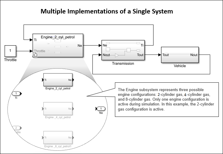
Variant Subsystem ブロックでは、コンポーネントの複数の実装を別個の階層に含めることができます。
たとえば、次の 3 つのエンジンの構成を取りうる車両を表すモデルのシミュレーションを行うとします。2 気筒ガソリン、4 気筒ガソリン、8 気筒ガソリン。各エンジン モデルを Variant Subsystem ブロック内で別個のサブシステムとして実装し、選択したTypes of Variant Control Modes in Variant Blocksに基づいてそれらのサブシステムを切り替えることができます。詳細については、バリアント制御の紹介を参照してください。
メモ
シミュレーション中は、Variant Subsystem ブロックの実装が 1 つだけアクティブになります。
Variant Subsystem ブロックは、バリアント選択肢として使用する 2 つ以上のブロックを含むように事前構成されたテンプレートです。これらの選択肢は、システムの複数の実装を表します。モデル実行中は、1 つの子ブロックのみがアクティブになります。アクティブな子ブロックは "アクティブなバリアント" と呼ばれます。
Variant Subsystem ブロック内の各バリアント選択肢は、[バリアント制御モード] と [バリアントのアクティベーションのタイミング] に関連付けられています。バリアント制御モードにより、アクティブなバリアントを選択する方法が決定されます。バリアントのアクティベーションのタイミングによって、選択をアクティブにするタイミングが決まります。さらに、生成されたコードに、アクティブな選択のみを含めるか、またはアクティブな選択と非アクティブな選択の両方を含めるかを決定します。
Variant Subsystem ブロックには、バリアント選択肢として、Subsystem ブロック、Model ブロック、または Subsystem Reference ブロックの組み合わせを含めることができます。Model ブロックのみを選択肢として持つ Variant Subsystem ブロックは、Variant Model ブロックと呼ばれます。詳細については、Variant Subsystem を使用した個別の階層でのバリエーションの実装を参照してください。追加や削除ができるのは外部ファイルからのみで、ブロック内ではできない、Model または Subsystem Reference ブロックを選択肢として持つ Variant Subsystem ブロックは、Variant Assembly Subsystem ブロックと呼ばれます。
バリアント選択肢以外に、Inport、制御端子 (Enable、Trigger、Reset、および Function-Call Subsystem)、Outport、または Connection Port (Simscape) ブロックを Variant Subsystem ブロック内に含めることができます。Variant Subsystem ブロック内のブロック間の接続は描画されません。ソフトウェアは、モデルのコンパイル中に、アクティブなバリアントを Variant Subsystem の Inport ブロックと Outport ブロックに自動的に接続します。バリアント選択肢を表すブロックには、親の Variant Subsystem ブロックの入力端子および出力端子とは異なる数の入力端子および出力端子を含めることができます。詳細については、Variant Subsystem 内のバリアント選択肢の入力端子と出力端子のマッピングを参照してください。
サブシステム ファイルにバリアント選択肢が保存されている Variant Subsystem ブロックを含むモデルを読み込むと、既定では、モデルの読み込み時間を最適化するためにアクティブな選択肢のみが読み込まれます。ただし、find_system、get_param、または set_param 関数を使用してプログラムでモデルを初期化した場合、非アクティブな選択肢が読み込まれることがあります。
Variant Subsystem ブロックを使用すると、次のことが可能です。
バリアント選択肢として Subsystem、Model、および Subsystem Reference ブロックを混在させる。
類似したインターフェイスを持たないモデル コンポーネントを作成する。Variant Subsystem 内で、複数のバリアント選択肢に対して異なる数の入力端子と出力端子を含めることができます。ただし、Variant Subsystem 内のバリアント選択肢の入力端子と出力端子のマッピングに記載されている条件を満たさなければなりません。
Variant Subsystem ブロックが 1 つのレイヤーにあり、バリアント選択肢が別のレイヤーにある階層的なブロック線図を作成する。
機能的に関連したブロックを 1 つに集約する。
モデルの複雑度を軽減する。
モデルのコンパイル中に、選択したバリアントのアクティベーションのタイミングに応じて、モデル全体で非アクティブなブロックをソフトウェアで削除する。
ブロック アイコンのバリアント バッジの色とアイコンは、そのブロックに設定されている [バリアントのアクティベーションのタイミング] パラメーター、[バリアント制御モード] パラメーター、および [Variant Subsystem の外部に条件を伝播する] パラメーターの値に基づいて変化します。詳細については、バリアントのバッジを参照してください。
例
Variant Subsystem を使用した個別の階層でのバリエーションの実装
Variant Subsystem の基本機能を学習する。

端子
シミュレーション中、ソフトウェアは Variant Subsystem ブロック内の非アクティブな端子を無効にします。
入力
出力
Variant Subsystem 内のバリアント選択肢の入力端子と出力端子のマッピング
Variant Subsystem ブロックでは、Subsystem、Model、または Subsystem Reference ブロックの組み合わせをバリアント選択肢として使用できます。Variant Subsystem ブロックが上流のモデル コンポーネントから受信する入力は、バリアント選択肢の入力端子と出力端子にマッピングされます。
バリアント選択肢を表すブロックには、親の Variant Subsystem ブロックの入力端子および出力端子とは異なる数の入力端子および出力端子を含めることができます。ただし、以下の条件を満たさなければなりません。
バリアント選択肢は、Variant Subsystem コンテナー ブロックと同じ入力端子のセットをもつか、コンテナー ブロックの端子のサブセットでなければなりません。
バリアント選択肢は、Variant Subsystem コンテナー ブロックと同じ出力端子のセットをもつか、コンテナー ブロックの端子のサブセットでなければなりません。
Variant Subsystem コンテナー ブロックに制御端子が含まれている場合:
すべてのバリアント選択肢における制御端子ブロックのタイプは、Variant Subsystem ブロックと同じでなければなりません。たとえば、Enabled Subsystem ブロックと Function-Call Subsystem ブロックを Variant Subsystem ブロック内の選択肢として使用することはできません。
Variant Subsystem ブロックの制御端子とそのバリアント選択肢の対応する制御端子は、同じ名前でなければなりません。たとえば、Variant Subsystem ブロックの制御端子の名前が
fcnである場合、そのバリアント選択肢すべての対応する制御端子の名前もfcnでなければなりません。
パラメーター
これらのパラメーターにアクセスするには、ブロック アイコンのバリアント バッジを右クリックし、[ブロック パラメーター] を選択します。詳細については、バリアントのバッジを参照してください。
アクティブなバリアント選択を決定するバリアント制御は次の型のいずれかにすることができます。
式— バリアント条件の評価に基づいてアクティブなバリアントが選択されます。条件式がtrueと評価される場合、対応するバリアント選択がアクティブになります。条件式がfalseと評価される場合、対応するバリアント選択が非アクティブになります。Switch Between Choices Using Condition Expressions in Variant Blocksを参照してください。ラベル— バリアントの名前に基づいてアクティブなバリアントが選択されます。バリアント制御は string であり、いずれのワークスペースでも、いずれの変数も作成する必要はありません。Switch Between Choices Using Labels in Variant Blocksを参照してください。sim/codegen の切り替え— いずれのワークスペース変数も作成せずに、シミュレーションとコード生成ワークフローのバリアントを自動的に切り替えます。モデルをシミュレートするときは、アクティブな選択肢としてsim分岐が自動的に選択されます。同様に、ソフトウェアインザループ (SIL) またはプロセッサインザループ (PIL) シミュレーションを実行したり、コードを生成したり、エクスターナル モードを使用したりするときは、codegen分岐が自動的に選択されます。Switch Between Choices for Simulation and Code Generation Workflows Without Using Control Variables in Variant Blocksを参照してください。
バリアント制御モードの詳細については、バリアント制御の紹介を参照してください。バリアント制御モードのさまざまな種類の比較については、Compare Different Types of Variant Control Modes in Variant Blocksを参照してください。
依存関係
使用できるさまざまなバリアントのアクティベーションのタイミングは、指定する [バリアント制御モード] の種類によって異なります。[バリアントのアクティベーションのタイミング] パラメーターに応じて、アクティブな選択肢が設定されるタイミングが決まります。生成されたコードに含まれる変動性も、このパラメーターで決まります。次の表に、それぞれのバリアント制御モードでサポートされるバリアントのアクティベーションのタイミングを示します。
| バリアントのアクティベーションのタイミング | |||||
|---|---|---|---|---|---|
| バリアント制御モード | ブロック線図の更新 | ブロック線図の更新時にすべての選択肢を解析 | コードのコンパイル | 起動 | ランタイム (Variant Subsystem ブロックのみ) |
式 | ✓ | ✓ | ✓ | ✓ | ✓ |
ラベル | ✓ | x | x | x | x |
sim/codegen の切り替え | ✓ | ✓ | x | x | x |
プログラムでの使用
ブロック パラメーター: VariantControlMode
|
| 型: 文字ベクトル |
値: 'expression' | 'label' | 'sim codegen switching' |
既定の設定: 'expression'
|
このパラメーターはシミュレーションおよびコード生成のワークフローに含める変動性を決定します。詳細については、Activate Variant During Different Stages of Simulation and Code Generation Workflowを参照してください。
ブロック線図の更新— モデルの実行時、シミュレーションおよびコード生成のワークフローにはアクティブな選択肢のみが含まれます。生成されたコードには、アクティブな選択肢のみが含まれます。ブロック線図の更新時にすべての選択肢を解析— モデルの実行時、アクティブな選択肢と非アクティブな選択肢の両方の一貫性がモデル全体で解析されます。ただし、シミュレーションおよびコード生成のワークフローにはアクティブな選択肢のみが含まれます。生成されたコードには、アクティブな選択肢のみが含まれます。コードのコンパイル— モデルの実行時、アクティブな選択肢と非アクティブな選択肢の両方の一貫性がモデル全体で解析され、すべての選択肢がシミュレーションおよびコード生成のワークフローに含まれます。生成されたコードにはアクティブな選択肢と非アクティブな選択肢の両方が、プリプロセッサ条件#ifと#elifに囲まれて含まれます。ただし、生成されたコードからビルドされる実行可能ファイルには、アクティブな選択肢のみが含まれます。起動— モデルの実行時、アクティブな選択肢と非アクティブな選択肢の両方の一貫性がモデル全体で解析され、すべての選択肢がシミュレーションおよびコード生成のワークフローに含まれます。このオプションでは、高速リスタートを使用して対話型シミュレーションの速度を向上させることができます。詳細については、Run Iterative Simulations Without Recompiling Model for Variant Systems Using Fast Restartを参照してください。モデルから生成されたコードには、通常のif条件で囲まれたアクティブな選択肢と非アクティブな選択肢の両方が含まれます。生成されたコードからビルドされる実行可能ファイルにも、アクティブな選択肢と非アクティブな選択肢の両方が含まれます。ランタイム— モデルの実行時、Parameter Writer ブロックを使用して生成コードのシミュレーション中や実行中にアクティブなバリアントを切り替えることができます。Parameter Writer ブロックは、条件付き実行サブシステムの内部、あるいは Initialize Function ブロック、Reinitialize Function ブロック、または Reset Function ブロックに配置します。ブロックの詳細については、イベント関数を参照してください。Parameter Writer ブロックを使用して、ブロック パラメーター、モデル ワークスペース変数、およびベース ワークスペース変数への書き込みが可能です。複数のバリアント制御変数は、アクティベーションのタイミングが[ランタイム]の場合、サポートされません。ランタイムのアクティベーションでは、Parameter Writer ブロックでサポートされるすべてのモデル化パターンが有効です。詳細については、Parameter Writer ブロックの一般的な使用法を参照してください。Variant Subsystem ブロックの [バリアントのアクティベーションのタイミング] パラメーターを
[ランタイム]に設定すると、非アクティブなバリアント選択肢の色は薄くなりません。この場合、Simulink エディターの [デバッグ] タブにある [情報のオーバーレイ] メニューの [バリアント フェージング] オプションの設定は無視されます。Simulink.VariantControl から継承— モデルの実行時、ブロックのSimulink.VariantControl型のバリアント制御変数からアクティベーションのタイミングが継承されます。バリアント ブロックにSimulink.VariantControl型のバリアント制御変数が複数ある場合、それらのすべての変数でアクティベーションのタイミングが同じでなければなりません。
次の表は、さまざまなバリアントのアクティベーションのタイミングについて、条件付きコード、バリアントの切り替え、状態の処理、および高速リスタートのサポートを基準に比較したものです。
update diagram または update diagram analyze all choices | code compile | startup | runtime | |
|---|---|---|---|---|
| 生成される条件付きコード | 非アクティブな条件付きコードは使用できません。 | プリプロセッサ マクロの内部に条件付きコードがあります。非アクティブな選択肢のコードは生成コードのコンパイル時に除外されます。 | if-elseif-else ステートメントの一部として条件付きコードが生成されます。実行中はバリアント制御変数の値を変更できません。 | if-elseif-else ステートメントの一部として条件付きコードが生成されます。実行中にバリアント制御変数の値を変更できます。 |
| シミュレーション中やコード実行中のバリアントの切り替え | サポートなし。 | サポートなし。 | サポートあり。起動時 (シミュレーション開始前の t = 0) にサポートされます。 | サポートあり。Parameter Writer ブロックを使用してバリアント制御変数を変更することにより、アクティブなバリアントが切り替わります。 |
| 状態の保持またはリセットのオプションの明示的な設定 | サポートなし。非アクティブなブロックについては状態がリセットされます。 | サポートなし。非アクティブなブロックについては状態がリセットされます。 | シミュレーション中は状態を変更できません。生成コードでは、バリアントを変更しようとすると、状態が保持された状態になります。 | 既定では状態が保持されます。State Writer ブロックを介して状態を明示的にリセットします。State Reader ブロックを使用して状態をもつブロックを読み取り、State Writer ブロックを使用して別の選択肢に移します。 |
| 実行可能ファイルのサイズ | サイズが小さい。非アクティブなバリアントについてはコードが生成されません。 | サイズが小さい。非アクティブなバリアントのコードはコンパイル時に削除されます。 | サイズが比較的大きい。アクティブなバリアントと非アクティブなバリアントの両方のコードを起動時の切り替えに使用できます。 | サイズが比較的大きい。アクティブなバリアントと非アクティブなバリアントの両方のコードを実行時の切り替えに使用できます。 |
| 高速リスタートのサポート | サポートなし。 | サポートなし。 | サポートあり。 | サポートあり。 |
依存関係
使用できるバリアントのアクティベーションのタイミングは、指定するバリアント制御モードの種類によって異なります。[バリアントのアクティベーションのタイミング] パラメーターに応じて、アクティブな選択肢がいつ設定されるかが決まります。生成されたコードに含まれる変動性も、このパラメーターで決まります。次の表に、それぞれのバリアント制御モードでサポートされるバリアントのアクティベーションのタイミングを示します。
バリアントのアクティベーションのタイミング バリアント制御モード ブロック線図の更新ブロック線図の更新時にすべての選択肢を解析コードのコンパイル起動ランタイム式✓ ✓ ✓ ✓ ✓ ラベル✓ x x x x sim/codegen の切り替え✓ ✓ x x x runtimeのアクティベーションのタイミングを使用した Variant Subsystem ブロックのアクティブなバリアント選択肢の切り替えを有効にするには、Parameter Writer ブロックを使用する必要があります。Parameter Writer ブロックの [保存先] パラメーターをバリアント制御変数の場所に基づいて設定し、[パラメーターの検証] を選択します。ブロック パラメーター— サブシステムのマスク パラメーターが制御変数である。モデル ワークスペース変数— モデル ワークスペースに制御変数がある。ベース ワークスペース変数— ベース ワークスペースまたはデータ ディクショナリに制御変数がある。
たとえば、サブシステムでマスク パラメーター
Vを作成し、それをバリアント条件式でバリアント制御に使用できます。バリアント制御条件のVの値が Parameter Writer ブロックによる書き込み先になります。
プログラムでの使用
ブロック パラメーター: VariantActivationTime
|
| 型: 文字ベクトル |
値: 'update diagram' | 'update diagram analyze all choices' | 'code compile' | 'startup'| 'runtime' |
既定の設定: 'update diagram'
|
Types of Variant Control Variables (Operands) in Variant Blocksにリストされている型の変数を指定すると、ソフトウェアは Variant Assembly Subsystem ブロックのバリアント選択肢に対してバリアント制御式を生成します。ここで指定した [バリアント制御変数] は生成された式の左辺であり、[バリアント選択肢列挙] のメンバーは生成された式の右辺です。両辺は == で接続されます。
バリアント制御変数は、アクティブなバリアント選択肢を変更するスイッチとして機能します。バリアント制御変数の値を指定してシミュレーションを実行します。シミュレーション中に、ソフトウェアはバリアント制御式を評価して、アクティブなバリアント選択肢を決定します。式が true に評価されると、対応するバリアント選択肢がアクティブに設定されます。アクティブなバリアントを変更するには、対応するバリアント制御式が true に評価され、そのバリアントがアクティブになるようにバリアント制御変数の値を変更します。
依存関係
このパラメーターは Variant Assembly Subsystem ブロックでのみ使用できます。このパラメーターを有効にするには、[バリアント制御モード] を [式] に設定します。
プログラムでの使用
ブロック パラメーター: VariantControlVariable
|
| 型: 文字ベクトル |
値: Simulink.VariantControl オブジェクト、スカラー変数、Simulink.Parameter オブジェクト、struct |
既定の設定: '' |
Model または Subsystem Reference ブロックをバリアント選択肢として Variant Assembly Subsystem ブロックに追加するには、対応するモデルまたはサブシステムのファイル名をメンバーとして含む列挙クラスの名前を指定します。その後、[バリアントの選択肢] テーブルの [リフレッシュ] ボタンを使用して列挙クラスを検証できます。検証が成功すると、列挙クラスのメンバーがバリアント選択肢として Variant Assembly Subsystem ブロックに追加されます。各選択肢には、左辺が [バリアント制御変数]、右辺がここで指定した [バリアント選択肢列挙] のメンバーであるバリアント制御式が含まれています。式の両辺は == で接続されます。新しく追加されたバリアント選択肢とそれに対応する制御式が、[バリアントの選択肢] テーブルに表示されます。
Variant Assembly Subsystem ブロックからバリアント選択肢を削除するには、ここで指定した列挙クラスから対応するメンバーを削除します。Variant Assembly Subsystem ブロック内からバリアント選択肢を管理することはできません。
指定する列挙クラスは、現在の MATLAB® セッションの検索パス上になければなりません。検索パスにファイルまたはフォルダーを追加する方法については、addpath を参照してください。
[バリアント選択肢列挙] パラメーターを使用して選択肢を追加する方法の詳細については、Add or Remove Variant Choices of Variant Assembly Subsystem Blocks Using External Filesを参照してください。
依存関係
このパラメーターは Variant Assembly Subsystem ブロックでのみ使用できます。このパラメーターを有効にするには、[バリアント制御モード] を [式] に設定します。
プログラムでの使用
ブロック パラメーター: VariantChoicesEnumeration
|
| 型: 文字ベクトル |
値: classdef または Simulink.defineIntEnumType を使用して定義された列挙クラス |
既定の設定: '' |
Model または Subsystem Reference ブロックをバリアント選択肢として Variant Assembly Subsystem ブロックに追加するには、対応するモデルまたはサブシステムのファイル名を指定します。ファイル名は、評価時に文字ベクトルの 1 次元 cell 配列を返す MATLAB 式または string の配列として指定する必要があります。その後、[バリアントの選択肢] テーブルの [リフレッシュ] ボタンを使用して式を検証できます。検証が成功すると、指定したファイルに対応するブロックがバリアント選択肢として Variant Assembly Subsystem ブロックに追加されます。選択肢ごとに、バリアント制御ラベルが生成されます。バリアント制御ラベルの名前は選択肢の名前と同じです。新しく追加されたバリアント選択肢とそれに対応する制御ラベルが、[バリアントの選択肢] テーブルに表示されます。
Variant Assembly Subsystem ブロックからバリアント選択肢を削除するには、このパラメーターで指定した式を変更します。Variant Assembly Subsystem ブロックのバリアント選択肢をブロック内から管理することはできません。
指定する MATLAB 式には、次のいずれかが含まれている必要があります。
現在の MATLAB セッションの検索パス上にあるモデルまたはサブシステムのファイル名。たとえば、指定子として
{'model1.slx', 'subsystemRef1.slx'}を指定すると、model1.slxファイルとsubsystemRef1.slxファイルに対応するブロックが Variant Assembly Subsystem ブロックのバリアント選択肢として追加されます。MATLAB パス上のモデルまたはサブシステムのファイル名に一致するファイル名パターン。パターン内のパスは、絶対パス、または Variant Assembly Subsystem ブロックを含むモデルの親フォルダーを基準とした相対パスにすることができます。たとえば、指定子として
{'folder_1/*.slx', 'folder_2/*.slx'}を指定すると、ソフトウェアは文字ベクトルfolder_1/*とfolder2/*をdir関数に渡します。この関数は、folder1およびfolder2フォルダー内にあるモデルおよびサブシステムのファイルを返します。返されたファイルに対応するブロックが、Variant Assembly Subsystem ブロックのバリアント選択肢として追加されます。
検索パスにファイルまたはフォルダーを追加する方法については、addpath を参照してください。
[バリアント選択肢指定子] パラメーターで選択肢を指定する方法の詳細については、Add or Remove Variant Choices of Variant Assembly Subsystem Blocks Using External Filesを参照してください。
依存関係
このパラメーターは Variant Assembly Subsystem ブロックでのみ使用できます。このパラメーターを有効にするには、[バリアント制御モード] を [ラベル] に設定します。
プログラムでの使用
パラメーター: VariantChoicesSpecifier
|
| 型: 文字ベクトル |
| 値: ファイル名の 1 次元 cell 配列またはファイル名のパターンに評価される任意の MATLAB 式。 |
既定の設定: '' |
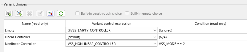
テーブルには、Variant Subsystem に含まれているバリアント選択肢ごとに 1 つの行があります。バリアント選択が存在しない場合、テーブルは空になります。
[バリアントの選択肢] テーブルの左にあるボタンを使用して、テーブルの要素を変更できます。
| 目的 | クリックするボタン |
|---|---|
| 新しいサブシステムの選択を作成して追加します: 新しい Subsystem ブロックをバリアントの選択肢として作成し、その新しい選択肢のエントリをテーブルに追加します。 |  |
| 新しいモデル バリアントの選択を作成して追加します: 新しい Model ブロックをバリアントの選択肢として作成し、その新しい選択肢のエントリをテーブルに追加します。 |  |
| 選択したバリアントの選択肢の削除: バリアント選択肢を完全に削除します。 |
|
選択されている Variant オブジェクトを作成/編集: メモ ベース ワークスペースを使用するモデルの場合、この操作によって |  |
| 選択されているバリアントの選択ブロックを開きます: 選択した行の Subsystem ブロックを開きます。 |  |
| Variant Subsystem の内容のダイアログ情報を更新: バリアント選択肢およびグローバル ワークスペース内のバリアント制御の値に従って、[バリアントの選択肢] テーブルを更新します。 |  |

依存関係
Variant Assembly Subsystem ブロックでは、選択したバリアント選択肢のみを開き、このセクションのボタンを使用してバリアント選択肢のリストを更新できます。Variant Assembly Subsystem ブロックに新しいバリアント選択肢を追加するには、Add or Remove Variant Choices of Variant Assembly Subsystem Blocks Using External Filesを参照してください。
この パラメーター は読み取り専用です。
このパラメーターは選択肢の名前を表示します。各選択肢には、ラベル、式、またはスイッチの形式のバリアント制御が含まれます。[ラベル] モードの Variant Assembly Subsystem の場合、個別のバリアント制御は使用できません。選択肢の名前は、アクティブな選択肢を設定するためのバリアント制御として使用されます。
選択肢の名前。string として指定されます。
依存関係
このパラメーターを有効にするには、[バリアント制御モード] を [ラベル] に設定します。
プログラムでの使用
ブロック パラメーターの値をプログラムで設定するには、関数 set_param を使用します。
ブロック パラメーターの値をプログラムで取得するには、関数 get_param を使用します。
| パラメーター: | VariantControl |
| 値: | variant control that is associated with the variant choice |
| データ型: | char |
例: set_param(gcb, 'VariantControl', 'V == 3'), where gcb is the variant choice of the Variant Subsystem block.
例: get_param(gcb, 'VariantControl'), where gcb is the variant choice of the Variant Subsystem block.
対応するバリアント選択肢をシミュレーション中にアクティブにするには、(sim) を指定します。対応するバリアント選択肢をコード生成ワークフロー (SIL、PIL、エクスターナル モードなど) の実行中にアクティブにするには、(codegen) を指定します。
依存関係
このパラメーターを有効にするには、[バリアント制御モード] を [sim/codegen の切り替え] に設定します。
プログラムでの使用
ブロック パラメーターの値をプログラムで設定するには、関数 set_param を使用します。
ブロック パラメーターの値をプログラムで取得するには、関数 get_param を使用します。
| パラメーター: | VariantControl |
| 値: | variant control that is associated with the variant choice |
| データ型: | char |
例: set_param(gcb, 'VariantControl', '(sim)'), where gcb is the variant choice of the Variant Subsystem block.
例: get_param(gcb, 'VariantControl'), where gcb is the variant choice of the Variant Subsystem block.
アクティブな選択肢を決定する条件式を指定します。条件式が true となる場合、対応するバリアント選択肢がアクティブになります。条件式が false となる場合、対応するバリアント選択肢が非アクティブになります。
バリアント制御は、次のいずれかにすることができます。
ラピッド プロトタイピングの場合は boolean の条件式。たとえば、
A == 1、A ~= B、A && B == 1など。条件の再利用の場合は条件式を含む
Simulink.VariantExpressionオブジェクト。Simulink.VariantExpression Objects for Variant Condition Reuse of Variant Blocksを参照してください。trueとなる選択肢がない場合は既定のバリアントの選択。
ここで A および B は "バリアント制御変数" と呼ばれるオペランドです。==、~=、および && は、条件式の演算子です。条件式には、そのようなバリアント制御変数と演算子を 1 つ以上含めることができます。バリアント制御変数のサポートされる型と保存場所の詳細については、Types of Variant Control Variables (Operands) in Variant BlocksおよびStorage Locations for Variant Control Variables (Operands) in Variant Blocksを参照してください。演算子の詳細については、Types of Operators in Variant Blocks for Different Activation Timesを参照してください。
詳細については、Switch Between Choices Using Condition Expressions in Variant Blocksを参照してください。
Variant Assembly Subsystem ブロックでは、このパラメーターは左辺を [バリアント制御変数] とする自動生成された boolean 式のリストであり、式の右辺には [バリアント選択肢列挙] のメンバーが入ります。式の両辺は == で接続されます。このパラメーターは読み取り専用です。
プログラムでの使用
ブロック パラメーターの値をプログラムで設定するには、関数 set_param を使用します。
ブロック パラメーターの値をプログラムで取得するには、関数 get_param を使用します。
Variant Subsystem ブロック:
| パラメーター: | VariantControl |
| 値: | variant control that is associated with the variant choice |
| データ型: | char |
例: set_param(gcb, 'VariantControl', 'V == 3'), where gcb is the variant choice of the Variant Subsystem block.
例: get_param(gcb, 'VariantControl'), where gcb is the variant choice of the Variant Subsystem block.
Variant Source ブロックと Variant Sink ブロック:
| パラメーター: | VariantControls |
| 値: | variant controls that are associated with variant choices |
| データ型: | char |
例: set_param(gcb, 'VariantControls', {'A == 1','A == 2'}), where gcb is the Variant Sink or Variant Source block.
例: get_param(gcb, 'VariantControls'), where gcb is the Variant Sink or Variant Source block.
この パラメーター は読み取り専用です。
このパラメーターには、Simulink.VariantExpression オブジェクトとして指定されている条件式が表示されます。条件式を変更または編集するには、ワークスペースでオブジェクトをダブルクリックすると表示される Simulink.VariantExpression パラメーター ダイアログ ボックスを使用します。
メモ
型 Simulink.VariantExpression の条件式で指定するオペランドは、ベース ワークスペースまたはデータ ディクショナリで定義されていなければなりません。マスクまたはモデル ワークスペースで定義されているオペランドの指定はサポートされません。
このリストには、バリアントの選択すべてのラベルが含まれています。アクティブな選択肢を設定するには、リストからラベルを選択します。対応する選択肢がアクティブになります。または、ラベル モードのアクティブな選択肢を変更するには、Set Active Choices Using Variant Control Labelsで説明している方法に従って変更できます。
依存関係
このパラメーターを有効にするには、[バリアント制御モード] を [ラベル] に設定します。
プログラムでの使用
パラメーター: LabelModeActiveChoice
|
| 型: 文字ベクトル |
| 値: ラベル モードのアクティブな選択肢が指定されていない場合、値は空です。ラベル モードのアクティブな選択肢が指定されている場合、値はアクティブな選択肢のバリアント制御ラベルです。 |
既定の設定: '' |
off— アクティブなバリアントの選択がないと、Simulink® でエラーが発生します。on— このオプションを選択すると、Simulink は、変更不可能なバリアント選択肢の項目を [バリアントの選択肢] テーブルに追加し、そのバリアント制御を(default)に設定します。この項目は、Variant Subsystem ブロックに表示されるバリアント選択肢として表示されません。シミュレーション中にアクティブなバリアント選択肢がない場合、Simulink は Variant Subsystem ブロックのバリアント選択肢を切断します。これにより、バリアント領域がモデルから完全に削除されます。サブシステムの非アクティブな出力端子はゼロを出力します。ゼロ以外の値を出力するには、Outport ブロックの [ソース非接続時に出力を指定] パラメーターを選択し、任意の値を指定します。
詳細については、Manage Variant Components to Pass Specified Values from Inactive Variant Subsystems with No Active Choice (Simulink Coder)を参照してください。
依存関係
このパラメーターは、Variant Subsystem に default のバリアント選択肢がなく、[バリアント制御モード] を [式] に設定している場合にのみ使用できます。
プログラムでの使用
パラメーター: EmptyChoice
|
| 型: 文字ベクトル |
値: 'off' | 'on' |
既定の設定: 'off' |
off— アクティブなバリアントの選択がないと、Simulink でエラーが発生します。on— このオプションを選択すると、Simulink は、変更不可能なバリアント選択肢の項目を [バリアントの選択肢] テーブルに追加し、そのバリアント制御を(default)に設定します。この項目は、Variant Subsystem ブロックに表示されるバリアント選択肢として表示されません。シミュレーション中にアクティブなバリアント選択肢がない場合、Simulink は Variant Subsystem ブロックのバリアント選択肢をバイパスします。入力端子と出力端子のみがアクティブなままになり、入力端子は値を出力端子に直接渡します。アクティブなバリアント選択肢がない場合に入力端子から出力端子に値をマッピングするには、Variant Subsystem ブロックに以下が必要です。
データ端子のみ (他のタイプの入力端子や出力端子なし)
同数のデータ入力端子と出力端子
バリアント選択肢の端子と完全に一致する入力端子と出力端子
詳細については、Manage Variant Components to Pass Specified Values from Inactive Variant Subsystems with No Active Choice (Simulink Coder)を参照してください。
依存関係
このパラメーターは、Variant Subsystem に default のバリアント選択肢がなく、[バリアント制御モード] を [式] に設定している場合にのみ使用できます。
プログラムでの使用
パラメーター: PassThrough
|
| 型: 文字ベクトル |
値: 'off' | 'on' |
既定の設定: 'off' |
[Variant Subsystem の外部に条件を伝播する] パラメーターを選択すると、ソフトウェアは、基となるブロックのバリアント条件を Variant Subsystem コンテナー ブロックに伝播して、サブシステムがそのインターフェイスを基となるブロックの状態に適応できるようにします。アクティブな選択肢の端子にマッピングされた端子がアクティブになります。非アクティブな選択肢の端子にマッピングされていない端子は非アクティブになります。このオプションを選択すると、Variant Subsystem の外部のコンポーネントが Variant Subsystem ブロック内のブロックのアクティブな状態と非アクティブな状態を確実に認識します。詳細については、Propagate Variant Conditions to Define Variant Regions Outside Variant Subsystems to Promote Consistency and Reduce ErrorsおよびPropagate Variant Conditions to Control Execution of Conditional Subsystemsを参照してください。
ブロック内のすべてのバリアント選択肢が同じインターフェイスを持つ場合、バリアント条件は Variant Subsystem ブロックの外部に伝播されません。
プログラムでの使用
パラメーター: PropagateVariantConditions
|
| 型: 文字ベクトル |
値: 'off' | 'on' |
既定の設定: 'off' |
Variant Subsystem のインターフェイスを柔軟にするかどうかを指定します。
on— Variant Subsystem ブロックの入力端子および出力端子とは異なる数の入力端子および出力端子を持つバリアント選択肢を使用してシミュレーションします。off— このオプションを指定してシミュレーションを実行すると、インターフェイスに不整合がある場合、ソフトウェアはエラーを生成し、バリアント選択肢の端子を Variant Subsystem ブロックに一致させるための修正アクションを示します。
プログラムでの使用
パラメーター: AllowFlexibleInterface
|
| 型: 文字ベクトル |
値: 'off' | 'on' |
既定の設定: 'on' |