Enable
イネーブル端子をサブシステムまたはモデルに追加
ライブラリ:
Simulink /
Ports & Subsystems
HDL Coder /
Ports & Subsystems
説明
Enable ブロックでは、外部信号でサブシステムまたはモデルの実行を制御できます。この機能を有効にするには、ブロックを Subsystem ブロックに追加するか、Model ブロックで参照されるモデルのルート レベルに追加します。
モデルのルート レベルでイネーブル端子を使用する場合は、次のようにします。
マルチ レート モデルでは、ソルバーをシングルタスクに設定します。
固定ステップ サイズをもつモデルでは、そのモデル内で少なくとも 1 つのブロックは指定した固定ステップ サイズのレートで実行しなければなりません。
例
Enabled Subsystem を使用した制御アルゴリズムの実装
この例では、Enabled Subsystem を使用してバイナリ論理信号に基づく制御アルゴリズムを実装する方法を示します。Enabled Subsystem は、バイナリ信号が正の値であり制御アルゴリズムを実装する場合に実行されます。この例では、スーパーツイスティング制御アルゴリズムを使用して、不安定な動的システムを安定させます。スーパーツイスティング アルゴリズムは、ロバスト性能でよく知られているスライディング モード制御手法の 1 つです。
Enabled Subsystem のブロック状態と出力の制御
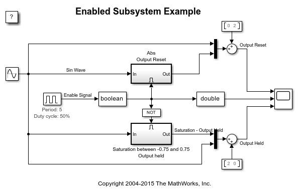
この例では、Enabled Subsystem ブロック内のブロックの状態を、Subsystem が無効化されたときにリセットまたは保持する方法と、Subsystem の出力を制御する方法を示します。この例では、離散制御信号と連続制御信号の両方について、状態と出力値の構成の 4 つの異なる組み合わせを見ていきます。Enabled Subsystem が無効化されたとき、次のような組み合わせが使用可能です。
条件付き実行サブシステムを使ったカウンター
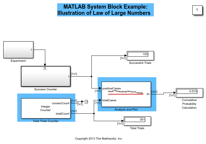
この例では、Enabled Subsystem および Triggered Subsystem を使用してカウンターを実装する方法を示します。この例では、モデル sldemo_counters がタンクへの水の流れを制御し、オーバーフローの発生回数をカウンターでカウントします。タンクの水位が 30 秒以上にわたって 8 メートル以上になるとオーバーフローが発生します。
クラッチ ロックアップ モデルの作成
この例では、Simulink® を使用して回転クラッチ システムをモデル化およびシミュレーションする方法を示します。ロックアップ時にシステム ダイナミクスにおいてトポロジーが変化するため、クラッチ システムのモデル化は困難ですが、この例題では、Enabled Subsystem がこのような問題をいかに簡単に処理できるかを示します。クラッチ シミュレーションの作成において重要な Simulink モデル化概念を採用する方法を説明します。設計者は、動的に変化する可能性がある強い不連続性と制約を伴う多くのモデルにこうした概念を適用できます。
端子
出力
Enabled Subsystem ブロックの外側に外部で接続され、サブシステムの内部に渡されるイネーブル信号。[出力端子の表示] パラメーターを選択すると、イネーブル信号端子は Enable ブロックに追加されます。
データ型: single | double | int8 | int16 | int32 | int64 | uint8 | uint16 | uint32 | uint64 | Boolean | fixed point | expression
パラメーター
Subsystem ブロックまたは Model ブロックが無効にされたときに、サブシステムまたはモデル内のブロックに関するブロックの状態がどのようになるかを選択します。
保持ブロックの状態を前の値で保持します。
リセットブロックの状態を初期条件 (定義されていない場合はゼロ) にリセットします。
プログラムでの使用
ブロック パラメーター: StatesWhenEnabling |
| 型: 文字ベクトル |
値: 'held' | 'reset' |
既定の設定: 'held' |
可変サイズの信号をいつ伝播するかを選択します。
イネーブルのときのみEnable 端子ブロックを含む Subsystem ブロックまたは Model ブロックを再度有効にするときに、可変サイズの信号を伝播します。このオプションを選択する場合、サンプル時間は周期的である必要があります。
実行中各タイム ステップで可変サイズの信号を伝播します。
プログラムでの使用
ブロック パラメーター: PropagateVarSize |
| 型: 文字ベクトル |
値: 'Only when enabling' | 'During execution' |
既定の設定: 'Only when enabling' |
出力端子は、Enabled Subsystem ブロックまたは有効な Model ブロックの外側に外部続されたイネーブル信号を、内部に渡します。
- オフ
Enable 端子ブロックで出力端子を削除します。
- オン
Enable 端子ブロックに出力端子を表示します。このオプションを選択すると、サブシステムまたはモデルでイネーブル信号を処理できます。
プログラムでの使用
ブロック パラメーター: ShowOutputPort |
| 型: 文字ベクトル |
値: 'off' | 'on' |
既定: 'off' |
モデルのゼロクロッシング検出を制御する。
- オン
ゼロクロッシングを検出します。
- オフ
ゼロクロッシングを検出しません。
プログラムでの使用
ブロック パラメーター: ZeroCross |
| 型: 文字ベクトル |
値: 'on' | 'off' |
既定値: 'on' |
Model ブロックに外部で接続され、ブロックの内部に渡されるイネーブル信号の次元を指定します。
1スカラー信号。
[n]幅
nのベクトル信号。[m n]m行n列をもつ行列信号。
プログラムでの使用
ブロック パラメーター: PortDimensions |
| 型: 文字ベクトル |
値: '1' | '[n]' | '[m n]' |
既定の設定: '1' |
ブロック メソッド実行の時間間隔を指定します。サンプル時間の指定を参照してください。
-1モデルから継承したサンプル時間。
TsTs が時間間隔のスカラー。
[Ts, To]Ts が時間間隔で To が初期時間オフセットのベクトル。
プログラムでの使用
ブロック パラメーター: SampleTime |
| 型: 文字ベクトル |
値: '-1' | 'Ts' | '[Ts, To]' |
既定: '-1' |
Model ブロックに外部で接続され、ブロックの内部に渡されるイネーブル信号の最小値を指定します。
Simulink® は、以下を行う際にこの値を使用します。
シミュレーション範囲のチェック。信号範囲の指定を参照してください。
固定小数点データ型の自動スケーリング
生成コードの最適化。この最適化により、アルゴリズム コードが削除され、SIL やエクスターナル モードなどの一部のシミュレーション モードの結果に影響を与えることがあります。Optimize using the specified minimum and maximum values (Embedded Coder)を参照してください。
[]未指定の最小値。
- 実数スカラー
実数で double のスカラー値。
プログラムでの使用
ブロック パラメーター: OutMin |
| 型: 文字ベクトル |
値: '[]' | 引用符で囲んだ実数スカラー |
既定の設定: '[]' |
Model ブロックに外部で接続され、ブロックの内部に渡されるイネーブル信号の最大値を指定します。
Simulink は、以下を行う際にこの値を使用します。
シミュレーション範囲のチェック。信号範囲の指定を参照してください。
固定小数点データ型の自動スケーリング
生成コードの最適化。この最適化により、アルゴリズム コードが削除され、SIL やエクスターナル モードなどの一部のシミュレーション モードの結果に影響を与えることがあります。Optimize using the specified minimum and maximum values (Embedded Coder)を参照してください。
[]未指定の最大値。
- 実数スカラー
実数で double のスカラー値。
プログラムでの使用
ブロック パラメーター: OutMax |
| 型: 文字ベクトル |
値: '[]' | 引用符で囲んだ実数スカラー |
既定の設定: '[]' |
Model ブロックに外部で接続され、ブロックの内部に渡されるイネーブル信号のデータ型を指定します。
double倍精度浮動小数点。
single単精度浮動小数点。
int8符号付き 8 ビット整数。
uint8符号なし 8 ビット整数。
int16符号付き 16 ビット整数。
uint16符号なし 16 ビット整数。
int32符号付き 32 ビット整数。
uint32符号なし 32 ビット整数。
int64符号付き 64 ビット整数。
uint64符号なし 64 ビット整数。
booleantrueまたはfalseの値をもつ boolean。fixdt(1,16)2 進小数点が未定義の符号付き 16 ビット固定小数点数。
fixdt(1,16,0)2 進小数点がゼロに設定された符号付き 16 ビット固定小数点数。
fixdt(1,16,2^,0)傾きが
2^0に設定され、バイアスが0に設定された符号付き 16 ビット固定小数点数。<data type expression>データ型オブジェクト。たとえば、
Simulink.NumericTypeなどです。データ型式としてSimulink.Busオブジェクトの名前を入力することはできません。
プログラムでの使用
ブロック パラメーター: OutDataTypeStr |
| 型: 文字ベクトル |
値: 'double' | 'single' | 'int8' | 'uint8' | 'int16' | 'uint16' | 'int32' | 'uint32' | 'int64' | 'uint64' | 'boolean' | '<fixdt(1,16)' | 'fixdt(1,16,0)' | 'fixdt(1,16,2^0,0)' | '<data type expression>' |
既定の設定: 'double' |
データ型カテゴリを選択し、ドロップダウン リストを表示して、データ型を定義しやすくします。
組み込み[データ型] と [データ型オーバーライド] のドロップダウン リストを表示します。
固定小数点[符号属性]、[スケーリング]、[データ型オーバーライド] のドロップダウン リストを表示します。
式式を入力するボックスを表示します。
依存関係
このパラメーターを有効にするには、[データ型アシスタントを表示] ボタンを選択します。
プログラムでの使用
同等のコマンド ライン パラメーターはありません。
ワークスペースからデータを読み込むときに、欠損しているワークスペース データの値を指定します。
- オン
対応するワークスペース データが存在しないタイム ステップで出力を線形内挿します。
- オフ
出力をタイム ステップで内挿しません。現在の出力は、データが存在する最も近いタイム ステップでの出力に等しくなります。
プログラムでの使用
ブロック パラメーター: Interpolate |
| 型: 文字ベクトル |
値: 'on' | 'off' |
既定の設定: 'on' |
ブロックの特性
データ型 |
|
直達 |
|
多次元信号 |
|
可変サイズの信号 |
|
ゼロクロッシング検出 |
|
拡張機能
C/C++ コード生成
Simulink® Coder™ を使用して C および C++ コードを生成します。
HDL Coder™ には、HDL の実装および合成されたロジックに影響する追加のコンフィギュレーション オプションがあります。
詳細については、Enabled SubsystemのHDL コード生成を参照してください。
このブロックには 1 つの既定の HDL アーキテクチャがあります。
PLC コード生成
Simulink® PLC Coder™ を使用して構造化テキスト コードを生成します。
固定小数点の変換
Fixed-Point Designer™ を使用して固定小数点システムの設計とシミュレーションを行います。
バージョン履歴
R2006a より前に導入
MATLAB Command
You clicked a link that corresponds to this MATLAB command:
Run the command by entering it in the MATLAB Command Window. Web browsers do not support MATLAB commands.
Web サイトの選択
Web サイトを選択すると、翻訳されたコンテンツにアクセスし、地域のイベントやサービスを確認できます。現在の位置情報に基づき、次のサイトの選択を推奨します:
また、以下のリストから Web サイトを選択することもできます。
最適なサイトパフォーマンスの取得方法
中国のサイト (中国語または英語) を選択することで、最適なサイトパフォーマンスが得られます。その他の国の MathWorks のサイトは、お客様の地域からのアクセスが最適化されていません。
南北アメリカ
- América Latina (Español)
- Canada (English)
- United States (English)
ヨーロッパ
- Belgium (English)
- Denmark (English)
- Deutschland (Deutsch)
- España (Español)
- Finland (English)
- France (Français)
- Ireland (English)
- Italia (Italiano)
- Luxembourg (English)
- Netherlands (English)
- Norway (English)
- Österreich (Deutsch)
- Portugal (English)
- Sweden (English)
- Switzerland
- United Kingdom (English)


