Connection Port
サブシステムの物理モデリング接続端子

ライブラリ:
Simulink /
Signal Routing
Simscape /
Utilities
Powertrain Blockset /
Utilities /
Simscape
RF Blockset /
Equivalent Baseband /
Input
RF Blockset /
Circuit Envelope /
Utilities
Vehicle Dynamics Blockset /
Utilities /
Simscape
説明
Connection Port ブロックは、サブシステムの境界を越えて物理接続または信号を伝達します。物理接続には、Simscape™ の保存および物理量信号の接続、Simscape Multibody™ の接続、Vehicle Dynamics Blockset™ 双方向接続端子などがあります。このブロックの機能は、Simulink® ライブラリの Inport ブロックや Outport ブロックと似ています。
サブシステムでは、その境界を越える物理接続ラインごとに Connection Port ブロックが必要です。Connection Port ブロックはサブシステム内に手動で配置できます。また、既存のネットワーク内にサブシステムを作成すると、Simulink によって Connection Port ブロックが自動的に挿入されます。
Subsystem ブロックでの端子の外観
Connection Port ブロックは、親の Subsystem ブロックに端子を追加します。端子タイプは、伝達する接続または信号によって決まります。Subsystem ブロックでの端子の外観は、そのサブシステム内で Connection Port ブロックが接続されている端子と一致します。たとえば、端子が Simscape の保存接続を伝達する場合、その端子は Subsystem ブロック上に Simscape 保存端子として表示されます。
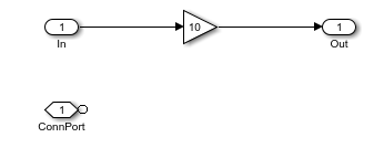
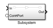
[In] および [Out] というラベルがそれぞれ付いた Simulink 入力端子および出力端子をもつサブシステムを考えます。このサブシステム内に Connection Port ブロックを配置し、未接続のままにした場合、親の Subsystem ブロック上の接続端子は白い丸として表示されます。
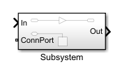
しかし、Connection Port ブロックを Mass ブロックに接続すると、親の Subsystem ブロック上にある接続端子の外観は、保存端子に変化します。
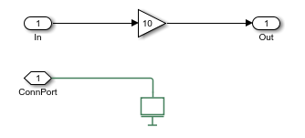
接続端子のタイプは機械並進になります。つまり、他のブロックの機械並進端子のみをこのサブシステムの端子に接続できます。
Subsystem ブロックでの端子の名前と位置
Simulink の入力端子および出力端子と同様に、端子ブロックに既定の名前が設定されている場合、サブシステム アイコン上の接続端子にはブロック名の代わりに端子番号が表示されます。既定の名前とパラメーターをもつ Connection Port ブロックをサブシステムに追加すると、接続端子には [端子番号] パラメーターの値がラベルとして付けられ、親の Subsystem ブロック アイコンの左側に配置されます。

端子をアイコンの右側に表示するには、[親サブシステムの端子の位置] パラメーターの値を [右] に変更します。

Simulink エディターの柔軟な端子配置機能により、端子をクリックしてブロック アイコンの輪郭に沿ってドラッグすることで、端子を移動できます。この方法により、上側や下側を含む、Subsystem ブロックの任意の側に端子を配置できます。[親サブシステムの端子の位置] パラメーターには、上側や下側用の個別の値はありません。Subsystem ブロック アイコン上の別の位置に端子をドラッグすると、パラメーターの値が自動的に変更され、新しい配置が反映されます。
左— 端子は、サブシステム アイコンの左側または上側に表示されます。右— 端子は、サブシステム アイコンの右側または下側に表示されます。
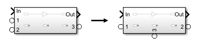
複数の接続端子がある場合、移動するたびに、必要に応じて、新しい端子の位置を反映するように端子インデックスの番号が自動的に再設定されます。たとえば、下図に示されているように Subsystem ブロックに 3 つの接続端子があり、端子 [2] をブロック アイコンの下側に移動した場合、端子 [2] と端子 [3] の番号が再設定されます。これらの 2 つの Connection Port ブロックの [端子番号] パラメーターの値は、新しい端子番号に合わせて自動的に変更されます。
親の Subsystem ブロックの向きも端子の位置に影響する場合があります。たとえば、親の Subsystem ブロックを左右反転させた場合、接続端子 [1] は、[親サブシステムの端子の位置] パラメーターで指定されている側の反対側に表示されます。

厳格なインターフェイスの指定
厳格なインターフェイス仕様を適用することで、ブロック端子の接続タイプを固定できます。たとえば、他のブロックの機械並進端子からの接続のみを受け入れるようにブロックを制限できます。Foundation のドメイン タイプのリストについては、ドメイン固有のライン スタイルを参照してください。ConnectionBus オブジェクトを使用する厳格なインターフェイスを適用した場合、Connection Port ブロックは Simscape Bus ブロックのバス端子にのみ接続できます。
[接続タイプ] パラメーターを使用して、特定のドメイン タイプや ConnectionBus オブジェクトなどの厳格なインターフェイスを指定します。厳格なインターフェイスの定義を適用すると、下図に示されているようにブロックの外観が変化します。
柔軟な接続
厳格なドメイン接続
厳格なバス接続

厳格なインターフェイス仕様を削除するには、[接続タイプ] パラメーターを [継承: 自動] に設定します。
例

永久磁石 DC モーター
この例では、テスト ハーネスおよび Simscape™ ブロックを使用して、DC モーターの無負荷速度、無負荷電流、および停動トルクのメーカー仕様を検証する方法を示します。
端子
保存
パラメーター
拡張機能
バージョン履歴
R2007a で導入