drivingScenario
ドライビング シナリオの作成
説明
drivingScenario オブジェクトは、ドライビング シナリオの道路、駐車場、車両、歩行者、障壁、その他の要素が含まれた 3-D アリーナを表します。このオブジェクトを使用して、現実的な交通シナリオをモデル化し、コントローラーまたはセンサー フュージョン アルゴリズムをテストするための合成検出を生成します。
道路を追加するには、関数
roadを使用します。道路に車線を指定するには、lanespecオブジェクトを作成します。関数roadNetworkを使用して、サードパーティの道路ネットワークから道路をインポートすることもできます。駐車場を追加するには、関数
parkingLotを使用します。アクター (車、歩行者、自転車など) を追加するには、関数
actorを使用します。車両専用に設計されたプロパティを備えたアクターを追加するには、関数vehicleを使用します。障壁を追加するには、関数barrierを使用します。車両および障壁を含む、すべてのアクターは一意のアクター ID をもつ直方体 (箱の形状) でモデル化されます。シナリオをシミュレートするために、ループ内で関数
advanceを呼び出します。これにより、一度に 1 つのタイム ステップずつシミュレーションを進めます。
ドライビング シナリオ デザイナー アプリを使用してドライビング シナリオを対話的に作成することもできます。また、アプリから drivingScenario オブジェクトをエクスポートして、アプリまたは Simulink® で使用するための複数のシナリオ バリエーションを生成できます。詳細については、プログラムでのドライビング シナリオのバリエーションの作成を参照してください。
作成
説明
scenario = drivingScenario
scenario = drivingScenario(Name,Value)SampleTime、StopTime、および GeoReference の各プロパティを設定します。たとえば、drivingScenario('GeoReference',[42.3 -71.0 0]) は、シーンの地理的原点を緯度と経度の座標 (42.3, –71.0)、および高度 0 に設定します。
プロパティ
オブジェクト関数
例
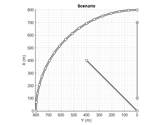
1 つの曲線道路、2 つの直線道路、2 つのアクター (車と自転車) が含まれたドライビング シナリオを作成します。どちらのアクターも 60 秒間道路に沿って移動します。
ドライビング シナリオ オブジェクトを作成します。
scenario = drivingScenario('SampleTime',0.1','StopTime',60);
半径 800 メートルの円弧に従う道路中心点を使用して、曲線道路を作成します。円弧は 0 度から開始して 90 度で終了し、5 度のインクリメントでサンプリングされます。
angs = [0:5:90]';
R = 800;
roadcenters = R*[cosd(angs) sind(angs) zeros(size(angs))];
roadwidth = 10;
cr = road(scenario,roadcenters,roadwidth);
両端の道路中央点を使用して、既定の幅をもつ 2 本の直線道路を追加します。最初の直線道路の両エッジに障壁を追加します。
roadcenters = [700 0 0; 100 0 0];
sr1 = road(scenario,roadcenters);
barrier(scenario,sr1)
barrier(scenario,sr1,'RoadEdge','left')
roadcenters = [400 400 0; 0 0 0];
road(scenario,roadcenters);
道路の境界を取得します。
rbdry = roadBoundaries(scenario);
車と自転車をシナリオに追加します。1 つ目の直線道路の最初の位置に車を配置します。
car = vehicle(scenario,'ClassID',1,'Position',[700 0 0], ...
    'Length',3,'Width',2,'Height',1.6);
道路を進んだ先に自転車を配置します。
bicycle = actor(scenario,'ClassID',3,'Position',[706 376 0]', ...
    'Length',2,'Width',0.45,'Height',1.5);
シナリオをプロットします。
plot(scenario,'Centerline','on','RoadCenters','on');
title('Scenario');
アクターの姿勢とプロファイルを表示します。
allActorPoses = actorPoses(scenario)
allActorPoses=242×1 struct array with fields:
    ActorID
    Position
    Velocity
    Roll
    Pitch
    Yaw
    AngularVelocity
allActorProfiles = actorProfiles(scenario)
allActorProfiles=242×1 struct array with fields:
    ActorID
    ClassID
    Length
    Width
    Height
    OriginOffset
    MeshVertices
    MeshFaces
    RCSPattern
    RCSAzimuthAngles
    RCSElevationAngles
このシナリオには障壁があり、各障壁セグメントがアクターと見なされているため、関数 actorPoses および関数 actorProfiles は、すべての静止アクターと非静止アクターの姿勢を返します。車両や二輪車など非静止アクターの姿勢とプロファイルのみを取得するには、まず scenario.Actors.ActorID プロパティを使用して、それらの対応するアクター ID を取得します。
movableActorIDs = [scenario.Actors.ActorID];
次に、それらの ID を使用して、非静止アクターの姿勢とプロファイルのみをフィルター処理します。
movableActorPoseIndices = ismember([allActorPoses.ActorID],movableActorIDs);

movableActorPoses = allActorPoses(movableActorPoseIndices)
movableActorPoses=2×1 struct array with fields:
    ActorID
    Position
    Velocity
    Roll
    Pitch
    Yaw
    AngularVelocity
movableActorProfiles = allActorProfiles(movableActorPoseIndices)
movableActorProfiles=2×1 struct array with fields:
    ActorID
    ClassID
    Length
    Width
    Height
    OriginOffset
    MeshVertices
    MeshFaces
    RCSPattern
    RCSAzimuthAngles
    RCSElevationAngles
ドライビング シナリオを作成し、シミュレーションの進行に伴うターゲット アウトラインの変化を示します。
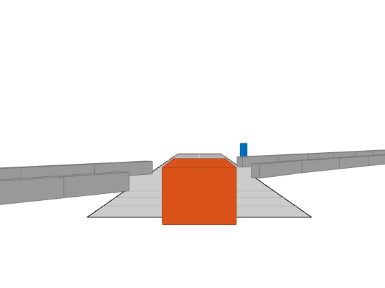
2 つの交差する直線道路で構成されたドライビング シナリオを作成します。1 つ目の道路セグメントの長さは 45 メートルです。2 つ目の直線道路は、長さが 32 メートルで、両端にジャージ障壁があり、1 つ目の道路と交差します。1 つ目の道路に沿って秒速 12.0 メートルで移動している車が、秒速 2.0 メートルで交差点を現在渡っている歩行者に近づいていきます。
scenario = drivingScenario('SampleTime',0.1,'StopTime',1);
road1 = road(scenario,[-10 0 0; 45 -20 0]);
road2 = road(scenario,[-10 -10 0; 35 10 0]);
barrier(scenario,road1)
barrier(scenario,road1,'RoadEdge','left')
ped = actor(scenario,'ClassID',4,'Length',0.4,'Width',0.6,'Height',1.7);
car = vehicle(scenario,'ClassID',1);
pedspeed = 2.0;
carspeed = 12.0;
smoothTrajectory(ped,[15 -3 0; 15 3 0],pedspeed);
smoothTrajectory(car,[-10 -10 0; 35 10 0],carspeed);
車両の自己を中心とした追跡プロットを作成します。
chasePlot(car,'Centerline','on')
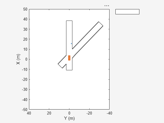
空の鳥瞰図プロットを作成し、アウトライン プロッターおよび車線境界線プロッターを追加します。次に、シミュレーションを実行します。各シミュレーション ステップは以下のとおりです。
追跡プロットを更新して、道路の境界およびターゲット アウトラインを表示する。
鳥瞰図プロットを更新して、更新した道路の境界およびターゲット アウトラインを表示する。プロットのパースペクティブは常に、自車が基準となっています。
bepPlot = birdsEyePlot('XLim',[-50 50],'YLim',[-40 40]);
outlineplotter = outlinePlotter(bepPlot);
laneplotter = laneBoundaryPlotter(bepPlot);
legend('off')

while advance(scenario)
    rb = roadBoundaries(car);
    [position,yaw,length,width,originOffset,color] = targetOutlines(car);
    [bposition,byaw,blength,bwidth,boriginOffset,bcolor,barrierSegments] = targetOutlines(car,'Barriers');
    plotLaneBoundary(laneplotter,rb)
    plotOutline(outlineplotter,position,yaw,length,width, ...
        'OriginOffset',originOffset,'Color',color)
    plotBarrierOutline(outlineplotter,barrierSegments,bposition,byaw,blength,bwidth, ...
        'OriginOffset',boriginOffset,'Color',bcolor)
    pause(0.01)
end
3 車線の道路に沿って走行している自車とターゲット車両が含まれたドライビング シナリオを作成します。Vision Detection Generator を使用して車線境界線を検出します。
scenario = drivingScenario;
車線指定を使用して 3 車線の道路を作成します。
roadCenters = [0 0 0; 60 0 0; 120 30 0];
lspc = lanespec(3);
road(scenario,roadCenters,'Lanes',lspc);
自車が 30 m/s で中央車線を追従するように指定します。
egovehicle = vehicle(scenario,'ClassID',1);
egopath = [1.5 0 0; 60 0 0; 111 25 0];
egospeed = 30;
smoothTrajectory(egovehicle,egopath,egospeed);
ターゲット車両が 40 m/s で自車の前を走行し、自車の近くで車線を変更するように指定します。
targetcar = vehicle(scenario,'ClassID',1);
targetpath = [8 2; 60 -3.2; 120 33];
targetspeed = 40;
smoothTrajectory(targetcar,targetpath,targetspeed);
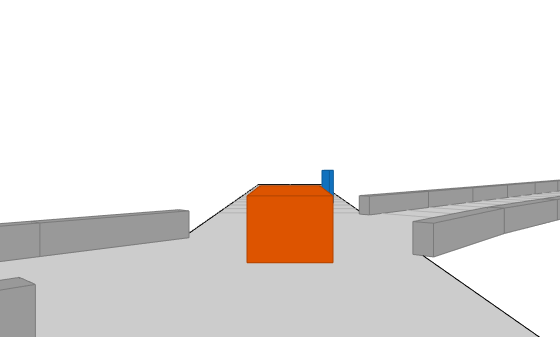
自車の後ろからのシナリオの 3-D ビューの追跡プロットを表示します。
chasePlot(egovehicle)

車線とオブジェクトを検出する Vision Detection Generator を作成します。センサーのピッチは 1 度下を指します。
visionSensor = visionDetectionGenerator('Pitch',1.0);
visionSensor.DetectorOutput = 'Lanes and objects';
visionSensor.ActorProfiles = actorProfiles(scenario);
シミュレーションを実行します。
鳥瞰図プロットおよび関連プロッターを作成します。
センサー カバレッジ領域を表示します。
車線区分線を表示します。
道路上のターゲットのグラウンド トゥルース姿勢を取得します。
60 m 前までの最適な車線境界線の点を取得します。
最適なターゲット姿勢および車線境界線から検出を生成します。
ターゲットのアウトラインを表示します。
オブジェクト検出が有効な場合はオブジェクト検出を表示します。
車線検出が有効な場合は車線境界線を表示します。
bep = birdsEyePlot('XLim',[0 60],'YLim',[-35 35]);
caPlotter = coverageAreaPlotter(bep,'DisplayName','Coverage area', ...
    'FaceColor','blue');
detPlotter = detectionPlotter(bep,'DisplayName','Object detections');
lmPlotter = laneMarkingPlotter(bep,'DisplayName','Lane markings');
lbPlotter = laneBoundaryPlotter(bep,'DisplayName', ...
    'Lane boundary detections','Color','red');
olPlotter = outlinePlotter(bep);
plotCoverageArea(caPlotter,visionSensor.SensorLocation,...
    visionSensor.MaxRange,visionSensor.Yaw, ...
    visionSensor.FieldOfView(1));
while advance(scenario)
    [lmv,lmf] = laneMarkingVertices(egovehicle);
    plotLaneMarking(lmPlotter,lmv,lmf)
    tgtpose = targetPoses(egovehicle);
    lookaheadDistance = 0:0.5:60;
    lb = laneBoundaries(egovehicle,'XDistance',lookaheadDistance,'LocationType','inner');
    [obdets,nobdets,obValid,lb_dets,nlb_dets,lbValid] = ...
        visionSensor(tgtpose,lb,scenario.SimulationTime);
    [objposition,objyaw,objlength,objwidth,objoriginOffset,color] = targetOutlines(egovehicle);
    plotOutline(olPlotter,objposition,objyaw,objlength,objwidth, ...
        'OriginOffset',objoriginOffset,'Color',color)
    if obValid
        detPos = cellfun(@(d)d.Measurement(1:2),obdets,'UniformOutput',false);
        detPos = vertcat(zeros(0,2),cell2mat(detPos')');
        plotDetection(detPlotter,detPos)
    end
    if lbValid
        plotLaneBoundary(lbPlotter,vertcat(lb_dets.LaneBoundaries))
    end
end


この例では、関数 addSensors を使用してドライビング シナリオにセンサーを追加し、個々のセンサー入力に基づいてグラウンド トゥルース ターゲット姿勢を取得します。次に、グラウンド トゥルース ターゲット姿勢を処理して検出にし、それらを可視化します。
ドライビング シナリオおよび鳥瞰図プロットの設定
自車および 2 台のターゲット車両が含まれるドライビング シナリオを作成します。一方のターゲット車両は自車の前方にあり、もう一方は自車の左側にあります。
[scenario, egovehicle] = helperCreateDrivingScenario;
自車の前方に取り付けるビジョン センサーを構成します。
visionSensor = visionDetectionGenerator(SensorIndex=1,SensorLocation=[4.0 0],Height=1.1,Pitch=1.0,DetectorOutput="Objects only");自車の左側に取り付ける超音波センサーを構成します。
leftUltrasonic = ultrasonicDetectionGenerator(SensorIndex=2,MountingLocation=[0.5 1 0.2],MountingAngles=[90 0 0],FieldOfView=[70 35],UpdateRate=100);
ドライビング シナリオを可視化する鳥瞰図プロットを作成します。
figHandle=figure(Name="BEP",Visible="on");
[detPlotter,lmPlotter,olPlotter,lulrdPlotter,luldetPlotter] = helperCreateBEP(visionSensor,leftUltrasonic,figHandle);

センサーの追加とドライビング シナリオのシミュレート
関数 addSensors を使用して、ビジョン センサーと超音波センサーの両方をドライビング シナリオに追加します。目的の車両のアクター ID を指定することにより、関数 addSensors を使用してドライビング シナリオ内の任意の車両にセンサーを追加できます。この例では、自車のアクター ID を指定します。
addSensors(scenario,{visionSensor,leftUltrasonic},egovehicle.ActorID);ドライビング シナリオをシミュレートします。それぞれのセンサー ID を関数 targetPoses への入力として指定することにより、個々のセンサーに基づいて別々のターゲット姿勢が取得されることに注意してください。この構文では、指定したセンサーの範囲のみでターゲットのグラウンド トゥルース姿勢が返されます。その後、グラウンド トゥルース姿勢をそれぞれのセンサー モデルに渡して検出を生成し、それらを可視化します。
while advance(scenario)
    % Plot scenario lane markings and vehicle outlines at current timestep
    [lmv,lmf] = laneMarkingVertices(egovehicle);
    plotLaneMarking(lmPlotter,lmv,lmf)
    [objposition,objyaw,objlength,objwidth,objoriginOffset,color] = targetOutlines(egovehicle);
    plotOutline(olPlotter,objposition,objyaw,objlength,objwidth, ...
        OriginOffset=objoriginOffset,Color=color)

    % Get ground-truth poses of targets in the range of vision and ultrasonic sensors separately
    tgtposeVision = targetPoses(scenario,visionSensor.SensorIndex);
    tgtposeUltrasonic = targetPoses(scenario,leftUltrasonic.SensorIndex);

    % Obtain detections based on targets only in range
    [obdets,obValid] = visionSensor(tgtposeVision,scenario.SimulationTime);
    [lobdets,lobValid] = leftUltrasonic(tgtposeUltrasonic,scenario.SimulationTime);

    helperPlotBEPVision(obdets,obValid,detPlotter)
    helperPlotBEPUltrasonic(lobdets,lobValid,leftUltrasonic,lulrdPlotter,luldetPlotter)
end

補助関数
helperCreateDrivingScenario は、道路および車両のプロパティを指定することにより、ドライビング シナリオを作成します。
function [scenario, egovehicle] = helperCreateDrivingScenario
    scenario = drivingScenario;
    roadCenters = [-120 30 0;-60 0 0;0 0 0; 60 0 0; 120 30 0; 180 60 0];
    lspc = lanespec(3);
    road(scenario,roadCenters,Lanes=lspc);

    % Create an ego vehicle that travels in the center lane at a velocity of 30 m/s.
    egovehicle = vehicle(scenario,ClassID=1);
    egopath = [1.5 0 0; 60 0 0; 111 25 0];
    egospeed = 30;
    smoothTrajectory(egovehicle,egopath,egospeed);

    % Add a target vehicle that travels ahead of the ego vehicle at 30.5 m/s in the right lane, and changes lanes close to the ego vehicle.
    ftargetcar = vehicle(scenario,ClassID=1);
    ftargetpath = [8 2; 60 -3.2; 120 33];
    ftargetspeed = 40;
    smoothTrajectory(ftargetcar,ftargetpath,ftargetspeed);

    % Add a second target vehicle that travels in the left lane at 32m/s.
    ltargetcar = vehicle(scenario,ClassID=1);
    ltargetpath = [-5.0 3.5 0; 60 3.5 0; 111 28.5 0];
    ltargetspeed = 30;
    smoothTrajectory(ltargetcar,ltargetpath,ltargetspeed);
end
helperCreateBEP は、ドライビング シナリオ シミュレーションを可視化するための鳥瞰図プロットを作成します。
function [detPlotter, lmPlotter, olPlotter, lulrdPlotter,luldetPlotter] = helperCreateBEP(visionSensor,leftUltrasonic,Figure)

    screenSize = double(get(groot,'ScreenSize'));
    Figure.Position = [screenSize(3)*0.17 screenSize(4)*0.15 screenSize(3)*0.4 screenSize(4)*0.6];
    clf(Figure);
    bepAxes = axes(Figure);
    grid(bepAxes,'on');

    bep = birdsEyePlot(Parent=bepAxes,XLim=[-20 60],YLim=[-35 35]);
    caPlotterV = coverageAreaPlotter(bep,DisplayName="Vision Coverage area",FaceColor="b");
    caPlotterU = coverageAreaPlotter(bep,DisplayName="Ultrasonic Coverage area",FaceColor="m");
    detPlotter = detectionPlotter(bep,DisplayName="Object detections");
    lmPlotter = laneMarkingPlotter(bep,DisplayName="Lane markings");
    olPlotter = outlinePlotter(bep);
    plotCoverageArea(caPlotterV,visionSensor.SensorLocation,...
        visionSensor.MaxRange,visionSensor.Yaw, ...
        visionSensor.FieldOfView(1));
    plotCoverageArea(caPlotterU,leftUltrasonic.MountingLocation(1:2),...
        leftUltrasonic.DetectionRange(3),leftUltrasonic.MountingAngles(1), ...
        leftUltrasonic.FieldOfView(1));

    lulrdPlotter = rangeDetectionPlotter(bep,DisplayName="Left Ultrasonic Ranges",LineStyle="-");
    luldetPlotter = detectionPlotter(bep,DisplayName="Point-On-Target (Left Ultrasonic)",MarkerFaceColor="k");
end
helperPlotBEPVision は、鳥瞰図プロット上にビジョン検出をプロットします。
function helperPlotBEPVision(obdets,obValid,detPlotter)

    if obValid
        detPos = cellfun(@(d)d.Measurement(1:2),obdets,UniformOutput=false);
        detPos = vertcat(zeros(0,2),cell2mat(detPos')');
        plotDetection(detPlotter,detPos)
    end

end
helperPlotBEPUltrasonic は、超音波領域の測定値と点をターゲット上にプロットします。
function helperPlotBEPUltrasonic(lobdets,lobValid,leftUltrasonic,lulrdPlotter,luldetPlotter)

    if ~isempty(lobdets) && lobValid
        lranges = lobdets{1}.Measurement;
        plotRangeDetection(lulrdPlotter,lranges,leftUltrasonic.FieldOfView(1),leftUltrasonic.MountingLocation,leftUltrasonic.MountingAngles)
        plotDetection(luldetPlotter,lobdets{1}.ObjectAttributes{1}.PointOnTarget(1:2)')
    end

end