FPGA、ASIC、および SoC 開発
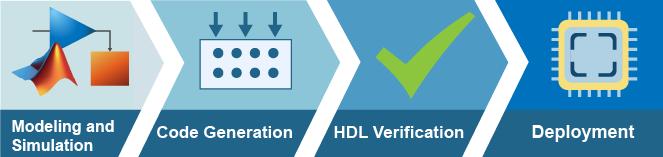
MATLAB® および Simulink® を使用して、FPGA、ASIC、および SoC デバイス上に展開するためのプロトタイプおよび量産アプリケーションを開発できます。MATLAB および Simulink を使用して、以下を行うことができます。
デジタル、アナログ、およびソフトウェアをともに高い抽象度でモデル化およびシミュレーションする。
自動ガイダンスを用いて固定小数点に変換したり、任意のターゲット デバイスに対するネイティブ浮動小数点演算を生成したりする。
メモリ、バス、および I/O をモデル化してハードウェア アーキテクチャおよびソフトウェア アーキテクチャを解析する。
デジタル ロジックに実装するために、最適化され、可読性に優れた、トレース可能な VHDL®、Verilog®、または SystemVerilog を生成する。
組み込みプロセッサをターゲットとするプロセッサに最適化済みの C/C++ コードを生成する。
MATLAB または Simulink のテスト ベンチに接続された HDL シミュレーター、FPGA または SoC デバイスで実行されているアルゴリズムを検証する。
FPGA、ASIC、および SoC 開発 向け製品
トピック
モデル化とシミュレーション
- HDL コード生成用の Simulink テンプレートの使用 (HDL Coder)
HDL コード生成用の Simulink モデル テンプレートを使用して、効率的なハードウェア設計を作成する。 - Transmit and Receive Tone Using AMD RFSoC Device - Part 1 System Design (SoC Blockset)
Design and simulate data path using SoC Blockset™ on Xilinx® RFSoC device. - ASIC、FPGA および SoC のための無線通信設計 (HDL Coder)
Wireless HDL Toolbox™ ブロックの使用によるハードウェアの無線通信アルゴリズムの設計。 - Implement Digital Downconverter for FPGA (DSP HDL Toolbox)
Design a digital downconverter (DDC) for LTE on FPGAs. - HDL OFDM Receiver (Wireless HDL Toolbox)
Implement OFDM-based wireless receiver optimized for hardware. - Convert MATLAB Vision Algorithm to Hardware-Targeted Simulink Model (Vision HDL Toolbox)
Create a hardware-targeted design in Simulink that implements the same behavior as a MATLAB reference design.
検証
- Simulink HDL コシミュレーション入門 (HDL Verifier)
Simulink ® 環境でコシミュレーション Wizard を使用して HDL Verifier ™ アプリケーションをセットアップします。 - FPGAインザループ シミュレーション (HDL Verifier)
FPGA インザループ (FIL) シミュレーションでは、Simulink または MATLAB ソフトウェアを使用して、既存の HDL コードの設計を実際のハードウェアでテストする機能が提供されます。 - データキャプチャワークフロー (HDL Verifier)
FPGA 上で実行されている設計から信号データをキャプチャするための高レベルの手順。 - JTAG ベースの AXI Manager を使用した FPGA メモリへのアクセス (HDL Verifier)
JTAG ベースの AXI manager を使用して、FPGA に接続されたメモリにアクセスします。 - UVM コンポーネント生成の概要 (HDL Verifier)
Simulink モデルからユニバーサル検証方法論 (UVM) 環境を生成します。 - SystemVerilog DPIコンポーネントを生成する (HDL Verifier)
Simulink から DPI コンポーネントを生成し、さまざまな構成パラメータを調べます。 - コンフィギュレーション パラメーターから HDL テスト ベンチを使用した生成されたコードの検証 (HDL Coder)
HDL テスト ベンチを生成して、設計に合わせて生成された HDL コードのシミュレーションおよび検証を行う。
コードの生成と展開
- HDL コード生成のワークフローの基礎 (HDL Coder)
MATLAB および Simulink アルゴリズムからの HDL コード生成と FPGA 合成のワークフローに従います。 - AXI-Stream インターフェイスを使用した IP コアの生成 (HDL Coder)
AXI4-Stream インターフェイスを使用して、Zynq® ハードウェアのプロセッサと FPGA の間の高速データ転送を可能にする。 - カスタム IP コアの生成 (HDL Coder)
HDL ワークフロー アドバイザーを使用し、モデルまたはアルゴリズムからカスタム IP コアを生成します。 - FPGA および SoC ハードウェアをターゲットにする方法の概要 (HDL Coder)
FPGA または SoC プラットフォームをターゲットにする手順の概要。 - Transmit and Receive Tone Using AMD RFSoC Device - Part 2 Deployment (SoC Blockset)
Implement and verify design using SoC Blockset on Xilinx RFSoC device. - Prototype Deep Learning Networks on FPGA and SoC Devices (Deep Learning HDL Toolbox)
Accelerate the prototyping, deployment, design verification, and iteration of your custom deep learning network running on a fixed bitstream by using thedlhdl.Workflowobject.
注目の例

Streaming Data from Hardware to Software
A systematic approach to design the data-path between hardware logic (FPGA) and embedded processor using SoC Blockset™.

FPGA インザループを使用した PID コントローラーの HDL 実装の検証
この例では、HDL Verifier™ を使用して FPGA インザループ(FIL) アプリケーションを設定する方法を示します。

Deploy and Verify YOLO v2 Vehicle Detector on FPGA
Deploy a you only look once (YOLO) v2 vehicle detector on FPGA and verify the end-to-end application using MATLAB.

永久磁石同期機のベクトル制御
永久磁石同期機 (PMSM) のベクトル制御 (FOC) アルゴリズムの HDL コードを生成する。

5G NR SIB1 Recovery Using Analog Devices AD9361/AD9364
Deploy a hardware-software co-design implementation of a SIB1 recovery algorithm for off-the-air 5G NR waveforms.

SystemVerilog DPI を使用して 5G ワイヤレス アプリケーションを検証する
この例では、SystemVerilog DPI コンポーネントを使用して HDL 環境で 5G ワイヤレス アプリケーションを検証する方法を示します。