制御アルゴリズムの設計
トルク制御サブシステムと速度制御サブシステムを作成し、ターゲット実行時間を検証し、制御ゲインを調整します。
カテゴリ
注目の例

Generate Motor Control Models for Selected Algorithm and Hardware
Use Motor Control Blockset™ to generate a Simulink® model that is configured for a specific hardware and motor control technique.

Algorithm-Export Workflows for Custom Hardware
Enables you to use any custom motor-control hardware (hardware not used in the Motor Control Blockset™ examples) to run a three-phase permanent magnet synchronous motor (PMSM) using field-oriented control (FOC). Using the algorithm export workflows, which involve generating code for the control algorithm by using Simulink® and Embedded Coder® and then integrating it with either manually written or externally generated hardware driver code. This example explains the algorithm export workflows along with the intermediate steps.

Swap Motors with Single Deployment of Sensorless FOC Algorithm
Run a permanent magnet synchronous motor (PMSM) in an industrial drive application setup using a sensorless field-oriented control (FOC) algorithm. The example uses a sensorless Flux Observer to estimate the motor position. Industrial drives enable you to replace a motor with a new one without repeated deployment of code. An industrial drive setup needs only nameplate parameters to adapt the software to the new motor.

AUTOSAR-Based FOC of PMSM
Implement an AUTOSAR-based field-oriented control (FOC) algorithm to run a permanent magnet synchronous motor (PMSM).

Field-Oriented Control of PMSM Using Position Estimated by Neural Network
Implement field-oriented control (FOC) of a permanent magnet synchronous motor (PMSM) using a rotor position estimated by an autoregressive neural network (ARNN) trained with Deep Learning Toolbox™.
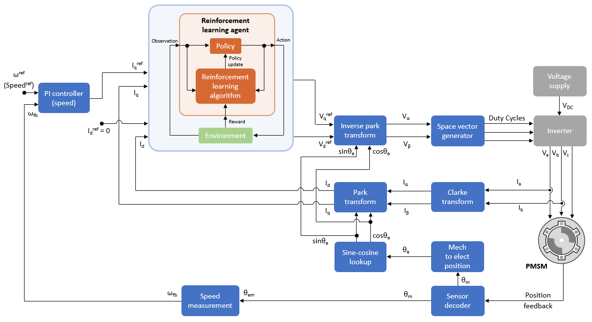
強化学習を使用した PMSM のベクトル制御
この例では、強化学習の制御設計法を使用して永久磁石同期モーター (PMSM) のベクトル制御 (FOC) を実装する方法を示します。この例では FOC の原理を使用します。ただし、PI コントローラーの代わりに強化学習 (RL) エージェントを使用します。FOC の詳細については、ベクトル制御を参照してください。
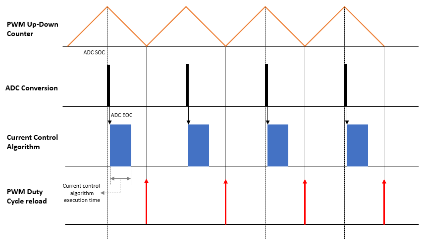
Motor Control Architectures Based on Different Current Sampling and PWM Frequencies
Enables you to implement different motor control architectures that use non-identical sampling rates for ADC conversion, PWM, and current controller algorithm to run a permanent magnet synchronous motor (PMSM) using field-oriented control (FOC).
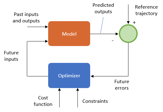
Run Field Oriented Control of PMSM Using Model Predictive Control
Uses Model Predictive Control (MPC) to control the speed of a three-phase permanent magnet synchronous motor (PMSM).
強化学習を使用した PMSM のベクトル制御
この例では、強化学習の制御設計法を使用して永久磁石同期モーター (PMSM) のベクトル制御 (FOC) を実装する方法を示します。この例では FOC の原理を使用します。ただし、PI コントローラーの代わりに強化学習 (RL) エージェントを使用します。FOC の詳細については、ベクトル制御を参照してください。

Determine Power Losses and THD for PWM Methods
Calculates the inverter power loss and total harmonic distortion (THD) in motor current for different pulse-width modulation (PWM) methods. The example uses field-oriented control (FOC) algorithm that runs a permanent-magnet synchronous motor (PMSM) in speed control mode as a reference. The example only supports simulation.
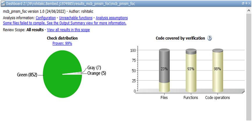
Analyze and Verify Motor Control Algorithms Using Polyspace
Uses the Polyspace® static code analysis tools to analyze and verify Simulink® models containing motor control algorithms. Static code analysis is a software verification technique that analyzes source code for quality, reliability, and security without executing the code. This approach uses robust error detection routines (that include checks for critical run-time errors) to identify bugs and defects and in addition ensures compliance with common coding standards. It provides a cost-effective alternative to measure and track the software quality metrics and eliminates the need to instrument the code or to write elaborate unit test cases.