Vector Plot
Plot vectors in space domain
Libraries:
Motor Control Blockset /
Signal Management
Description
The Vector Plot block plots and tracks the changes in vectors in the space domain. You can use the block to visualize vectors for electrical quantities (such as voltage and current) and track their changes in real time by using the trace left behind by the vector tip.
The block accepts vector magnitudes and their angles (in radians, per-unit, or degrees) as inputs and provides a pictorial representation of the vectors. The block also traces the plot history of the vector tip according to the selected number of points.
For details about how to use the Vector Plot block, see the model
mcb_pmsm_foc_qep_f28379d in Field-Oriented Control of PMSM Using Quadrature Encoder.
Ports
Input
Voltage components in the three-phase system in the abc reference frame. The port accepts three voltage components multiplexed by using Mux.
Dependencies
To enable this port, set Select input types to
Vabc Iabc Theta.
Data Types: single | double
Current components in the three-phase system in the abc reference frame. The port accepts three current components multiplexed by using Mux.
Dependencies
To enable this port, set Select input types to
Vabc Iabc Theta.
Data Types: single | double
Angle value (in radians, per-unit, or degrees for Vabc and
Iabc) between the rotating reference frame and the
α-axis.
The figures show the angle of transformation when:
The d-axis aligns with the α-axis.
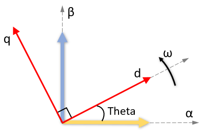
The q-axis aligns with the α-axis.
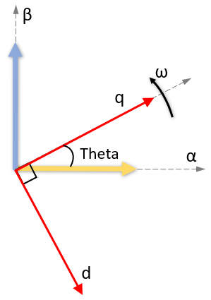
In both cases, the angle is Theta = ωt, where:
Theta is the angle between the α- and d-axes for the d-axis alignment or the angle between the α- and q-axes for the q-axis alignment. It indicates the angular position of the rotating dq reference frame with respect to the α-axis.
ω is the rotational speed in the d-q reference frame.
t is the time in seconds from the initial alignment.
Dependencies
To enable this port, set Select input types to
Vabc Iabc Theta and set Select reference
frame to Rotating Reference Frame.
Data Types: single | double
Direct and quadrature axis voltage components in the rotating dq reference frame. The port accepts two voltage components multiplexed by using Mux.
Dependencies
To enable this port, set Select input types to
Vdq Idq.
Data Types: single | double
Direct and quadrature axis current components in the rotating dq reference frame. The port accepts two currents components multiplexed by using Mux.
Dependencies
To enable this port, set Select input types to
Vdq Idq.
Data Types: single | double
Magnitudes of vectors that you want to plot. The port accepts up to six vector magnitudes multiplexed by using Mux. The vector magnitudes correspond to the angle values input to the Angle port.
Note
The number of multiplexed vector magnitudes should be same as the number of multiplexed angles input to the Angle port.
Dependencies
To enable this port, set Select input types to
Mag Angle.
Data Types: single | double
Angle values (in radians, per-unit, or degrees) of vectors that you want to plot. The port accepts up to six vector angles multiplexed by using Mux. The angle values correspond to the vector magnitudes input to the Magnitude port.
Note
The number of multiplexed vector angles should be same as the number of multiplexed magnitudes input to the Magnitude port.
Dependencies
To enable this port, set Select input types to
Mag Angle.
Data Types: single | double
Parameters
Types of input ports available for the block.
Select type of reference frame that the block uses to plot the input vectors:
Rotating Reference Frame— Select this option to plot the three-phase voltage and current vectors in the rotating dq reference frame.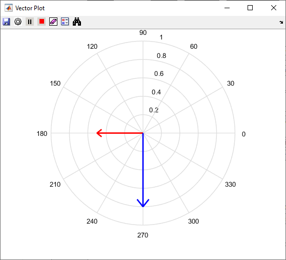
Stationary Reference Frame— Select this option to plot the three-phase voltage and current vectors in the stationary αβ reference frame.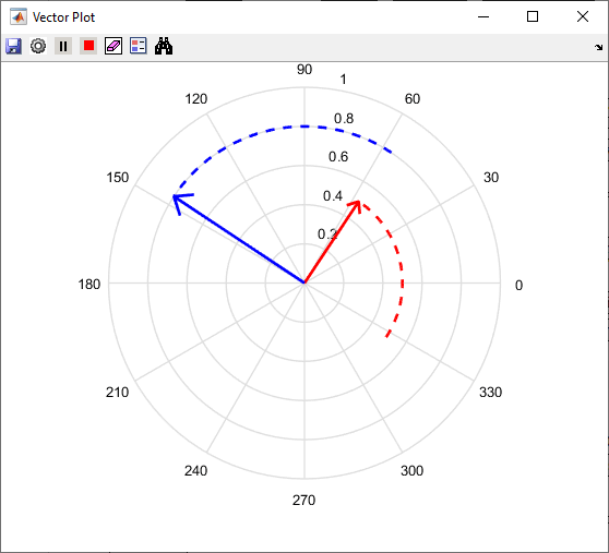
Dependencies
To enable this parameter, set Select input types to
Vabc Iabc Theta.
Align either the d- or q-axis of the rotating reference frame to the α-axis of the stationary reference frame.
Dependencies
To enable this parameter, set Select input types to
Vabc Iabc Theta and Select reference
frame to Rotating Reference Frame.
Unit of Theta input value.
Dependencies
To enable this parameter, set Select input types to
Vabc Iabc Theta and Select reference
frame to Rotating Reference Frame.
Unit of Angle input value.
Dependencies
To enable this parameter, set Select input types to
Mag Angle.
Select this parameter to automatically open the vector plot window when simulation begins.
Showplot — Click this button to open the vector plot window.
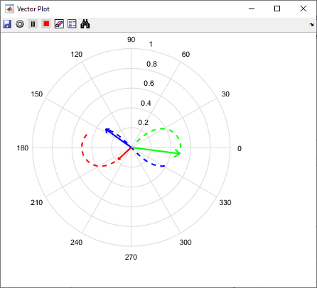
Vector Plot Window
This example shows the plot when you set Select input types to
Mag Angle and provide three multiplexed magnitudes and three
multiplexed angles as inputs.
You can use these buttons on the Vector Plot window:
 (Save Figure) — Click to save the plot to an
image.
(Save Figure) — Click to save the plot to an
image. (Preferences) — Click to open the Preferences dialog
box.
(Preferences) — Click to open the Preferences dialog
box.Display traces (samples) — Enter the number of samples that you want to trace for the vector tip. By default, the field uses the value
100.Auto-Scale — Select this field to automatically scale the axes limit. The block performs auto-scaling every at every
1000points of simulation.Axes limit — Enter the maximum value of the x and y axis that the plot should use. By default, the field uses the value
1. If you select Auto-Scale and the vector magnitude increases beyond the selected axes limit, the limit on the Vector Plot window extends automatically to accommodate the vector magnitude.
 (Run Simulation) — Click to simulate the model that
contains the Vector Plot block.
(Run Simulation) — Click to simulate the model that
contains the Vector Plot block. (Pause Simulation) — Click to pause simulation.
 (Stop Simulation) — Click to stop simulation.
 (Clear Data History) — Click to clear the vector
tracing history.
(Clear Data History) — Click to clear the vector
tracing history. (Insert Legend) — Click to insert or remove the legend
describing the vectors. You can manually change the default legend description.
(Insert Legend) — Click to insert or remove the legend
describing the vectors. You can manually change the default legend description.
 (Auto Scale) — Click to turn on or turn off the
auto-scale function.
(Auto Scale) — Click to turn on or turn off the
auto-scale function.
Extended Capabilities
Version History
Introduced in R2020b