Park Transform
αβ から dq への変換の実装
ライブラリ:
Motor Control Blockset /
Controls /
Math Transforms
Motor Control Blockset HDL Support /
Controls /
Math Transforms
説明
Park Transform ブロックは、静止 αβ 基準座標系における二相直交成分 (α、β) または多重化された αβ0 成分の Park 変換を計算します。
このブロックは次の入力を受け取ります。
静止基準座標系における α-β 軸成分または多重化された成分 αβ0。[入力数] パラメーターを使用して 2 つまたは 3 つの入力を使用します。
変換の対応する角度の正弦値と余弦値。
2 入力構成を使用する場合、回転 dq 基準座標系における直交直 (d) 軸成分および横 (q) 軸成分を出力します。3 入力構成を使用する場合、多重化された成分 dq0 を出力します。
平衡システムの場合、ゼロ成分はゼロに等しくなります。
このブロックでは、d 軸または q 軸を時間 t = 0 において α 軸に揃えるように構成できます。
次の図は、以下の場合の αβ 基準座標系と回転 dq 基準座標系における α-β 軸成分を示しています。
d 軸が α 軸と揃っている。
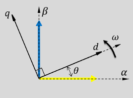
q 軸が α 軸と揃っている。
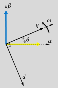
どちらの場合も、角度は θ = ωt です。
θ は、d 軸に揃える場合は α 軸と d 軸の間の角度、q 軸に揃える場合は α 軸と q 軸の間の角度です。α 軸に対する回転 dq 基準座標系の角度位置を示します。
ω は、d-q 基準座標系の回転速度です。
t は、最初の配置からの時間 (秒数) です。
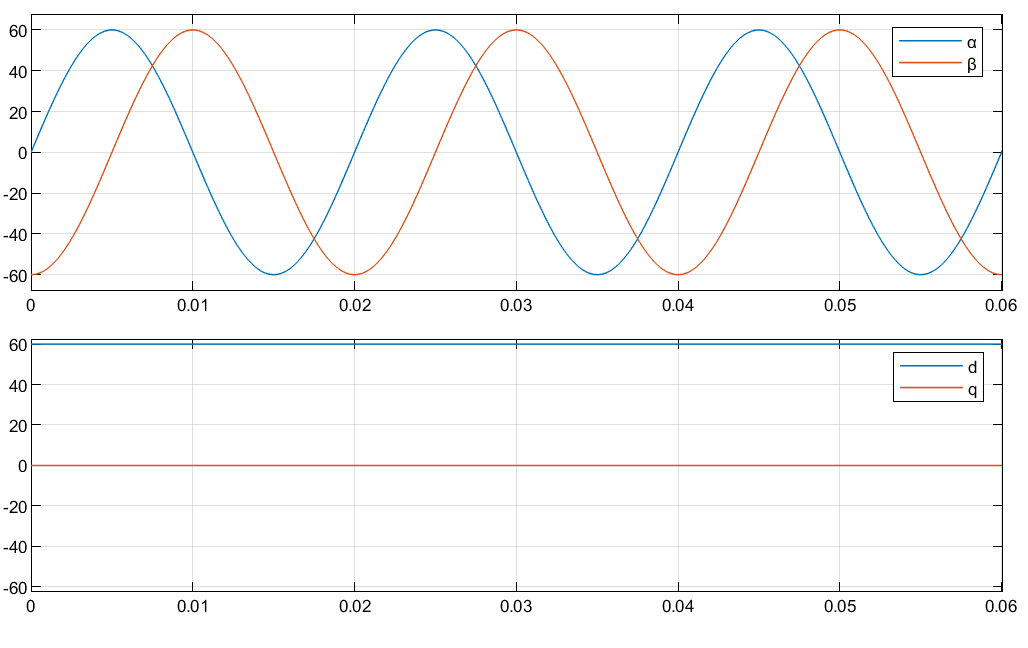
次の図は、以下の場合の αβ 基準座標系と dq 基準座標系の各成分の時間応答を示しています。
d 軸が α 軸と揃っている。
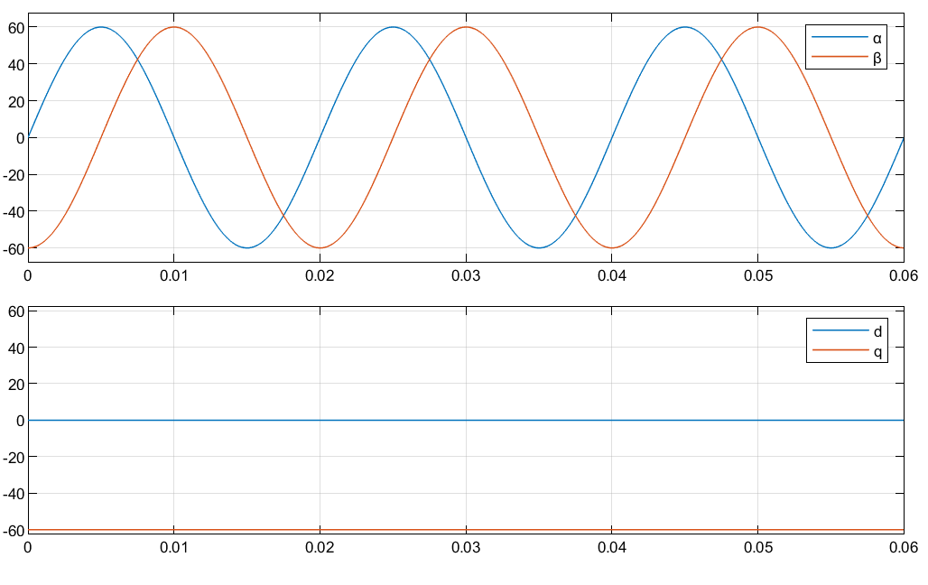
q 軸が α 軸と揃っている。
方程式
[入力数] パラメーターが [2 つの入力] に設定されている場合、ブロックによる Park 変換の実装方法は次の方程式で記述されます。
d 軸が α 軸と揃っている場合。
q 軸が α 軸と揃っている場合。
ここで、
と は、静止 αβ 基準座標系における二相直交成分です。
と は、回転 dq 基準座標系における直軸および横軸直交成分です。
[入力数] パラメーターが [3 つの入力] に設定されている場合、ブロックによる Park 変換の実装方法は次の方程式で記述されます。
Clarke to Park Angle Transform ブロックは、a 相から q 軸の配置の変換を次のように実装します。
ここで、
α と β は、静止基準座標系における二相システムの alpha 軸成分と beta 軸成分です。
0 はゼロ成分です。
d と q は、回転基準座標系における 2 軸システムの直軸成分と横軸成分です。
a 相から d 軸の配置の場合、ブロックは次の方程式を使用して変換を実装します。
例

速度センサーを使用した誘導モーターのベクトル制御
この例では、三相交流誘導モーター (ACIM) の角速度を制御するためのベクトル制御 (FOC) 手法を実装します。この FOC アルゴリズムには回転子の速度フィードバックが必要であり、この例ではそれを直交エンコーダー センサーを使用して取得します。FOC の詳細については、ベクトル制御を参照してください。

PMSM の弱め界磁制御 (MTPA を使用)
この例では、三相永久磁石同期モーター (PMSM) のトルクと角速度を制御するためのベクトル制御 (FOC) 手法を実装します。この FOC アルゴリズムには回転子の位置フィードバックが必要であり、それを直交エンコーダー センサーで取得します。FOC の詳細については、ベクトル制御を参照してください。

ホール センサーを使用した PMSM のベクトル制御
この例では、三相永久磁石同期モーター (PMSM) の角速度を制御するためのベクトル制御 (FOC) 手法を実装します。この FOC アルゴリズムには回転子の位置フィードバックが必要であり、それをホール センサーで取得します。FOC の詳細については、ベクトル制御を参照してください。
端子
入力
出力
パラメーター
拡張機能
バージョン履歴
R2020a で導入