このページの内容は最新ではありません。最新版の英語を参照するには、ここをクリックします。
開ループ制御と閉ループ制御
このセクションでは、開ループと閉ループのモーター制御手法について説明します。
開ループ モーター制御
開ループ制御 (スカラー制御またはボルト/ヘルツ制御とも呼ばれる) は、任意の AC モーターの駆動に使用できる一般的なモーター制御手法です。この手法はシンプルであり、モーターからのフィードバックをまったく必要としません。
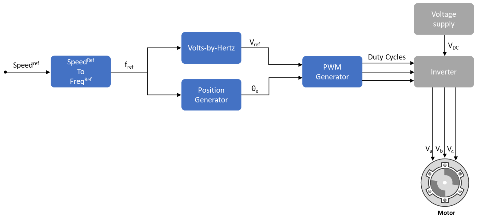
この図は開ループ制御システムを示しています。電源回路は、DC 電源から供給される PWM 電圧源インバーターで構成されています。このシステムでは、制御の実装にいずれのフィードバック信号も使用していません。指令速度を使用して固定子電圧の周波数を決定しています。このシステムでは、磁束が一定に維持されるように、電圧の振幅が定格電圧と定格周波数の比 (一般にボルト/ヘルツ比と呼ばれる) に比例するものとして計算されます。
ここで、
はモーターの定格磁束 (Wb) です。
は AC モーターの固定子電圧 (ボルト) です。
は AC モーターの固定子電圧の周波数 (Hz) です。
開ループ システムでは、AC モーターの速度は次のように表されます。
ここで、
は AC モーターの機械速度 (rpm) です。
は AC モーターの固定子電圧と電流の周波数 (Hz) です。
はモーターの極対数です。
(与えられた機械について) 求められる指令速度 RPMref に達するのに必要な指令電圧の周波数 fref は、次の方程式で求められます。
この周波数を使用してインバーターの PWM 指令電圧を生成します。次のように、ボルト/ヘルツ比を維持して電圧の振幅を計算します。
システムで指令電圧周波数 (fref) から PWM 指令電圧 (Vref) のピーク振幅を計算する際、定格周波数に対する定格電圧の比 (Vrated / frated) が一定に維持されます。三相電圧波形の電圧/周波数の比を一定に (つまり Vref が fref に比例するように) 維持することで、固定子の磁束が比較的一定になります。ただし、次の図に示すように、モーター速度の全範囲にわたって V/F 比が一定になるわけではありません。

領域 A — 比較的低い速度では、システムは固定子抵抗の電圧低下の影響を取り除くために最小ブースト電圧 (定格電圧の 15% または 25%) を必要とします。電圧 Vmin は、この低下に対する補正として機能します。
領域 B — この領域では、システムは Vrated / frated 比を一定に維持します。fref に従って Vref を計算することで V/F 制御に追従します。
領域 C — 比較的高い速度では、固定子電圧が Vrated に制限されるため、システムは一定の V/F 比を維持できません。この領域では、fref が上昇しても、Vref は Vrated と等しいままになります。
pu 単位系の表現を使用している場合、開ループ制御システムでは Vrated が基準量と見なされ、通常はこれが 1PU つまりデューティ比 100% に対応します。変調方式 (正弦波 PWM または空間ベクトル PWM) によっては、追加のゲイン (正弦波 PWM の場合は ) が必要になることがあります。
開ループ制御は、動的応答は重要でないアプリケーションにおいて、費用対効果の高いソリューションが必要な場合に使用できます。開ループ モーター制御では、モーターの角速度に影響を与える可能性がある外部の条件については考慮できません。そのため、目的のモーター速度と実際のモーター速度の間の偏差を制御システムで自動的に補正することはできません。
メモ
スカラー制御の実装では、固定子抵抗や弱め界磁による電圧低下の補正は考慮されません。
閉ループ モーター制御
閉ループ制御では、システムのフィードバックが制御で考慮されます。モーターの閉ループ制御では、電流や位置などのモーター信号のフィードバックが考慮されます。制御システムは、フィードバック信号を使用して、指令値でのモーターの応答を維持するように (モーターに印加される) 電圧を調整します。
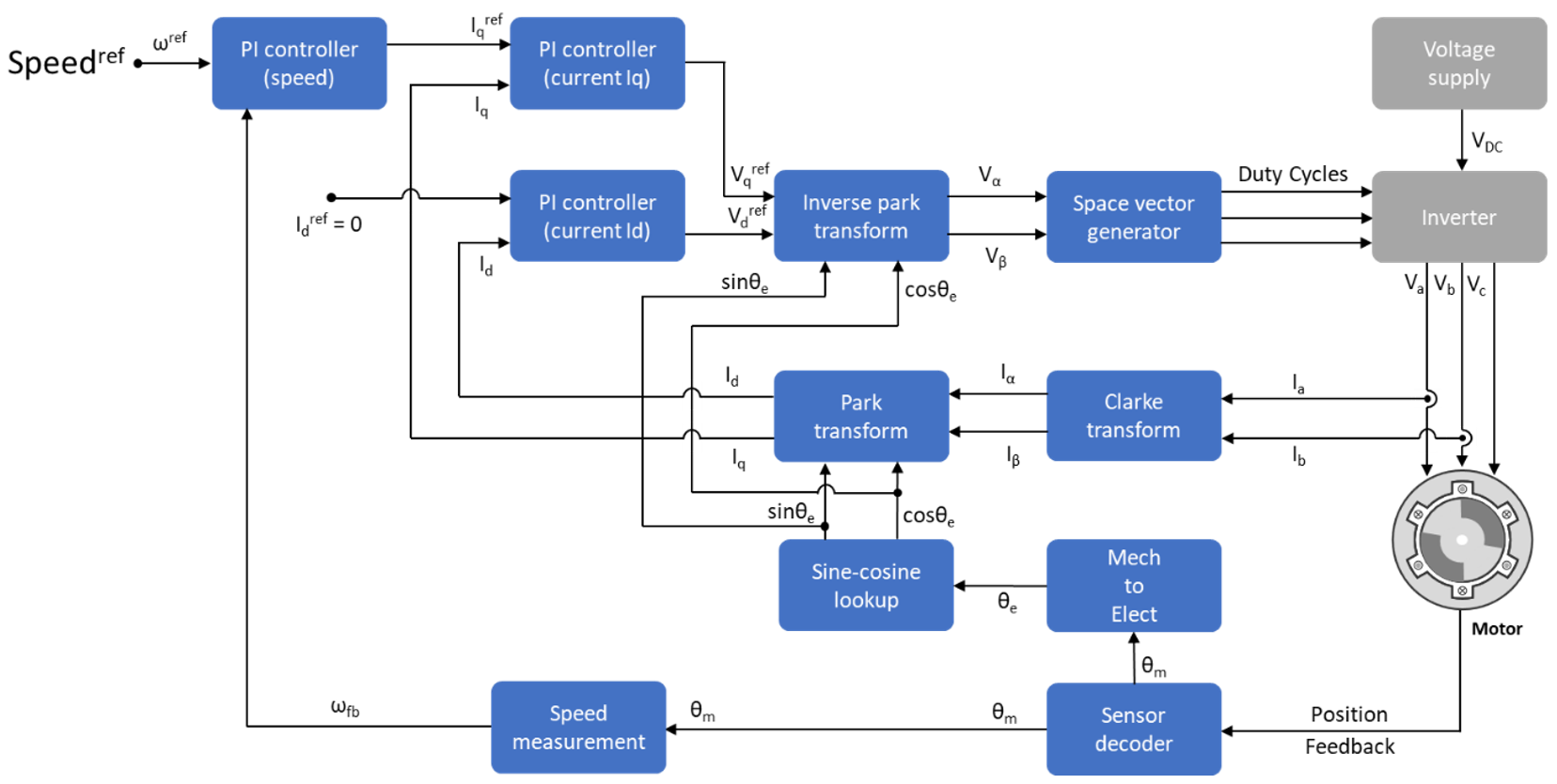
ベクトル制御 (FOC) は、モーター制御アプリケーションで使用される一般的な閉ループ システムです。モーターのトルク、速度、位置の閉ループ制御の実装に FOC の手法が使用されます。また、この手法はトルクと速度の全範囲について優れた制御機能を提供します。FOC の実装には、静止基準座標系から回転子鎖交磁束基準座標系への固定子電流の変換が必要です。
よく使用される FOC の制御モードは、速度制御とトルク制御です。位置制御モードは、それに比べるとあまり使用されません。ほとんどのトラクション アプリケーションで、モーター制御システムが指令トルク値に追従するトルク制御モードが使用されています。速度制御モードでは、モーター コントローラーが指令速度値に追従し、内側のサブシステムを形成するトルク制御に対するトルク指令を生成します。一方、位置制御モードでは、速度コントローラーが内側のサブシステムを形成します。
FOC アルゴリズムの実装には、電流と回転子位置のリアルタイムのフィードバックが必要になります。電流と回転子位置はセンサーを使用して測定できます。実際のセンサーベースの測定の代わりに推定フィードバック値を使用するセンサーレスの手法も使用できます。
閉ループ制御では、位置と固定子電流のリアルタイムのフィードバックを使用して、速度コントローラーと電流コントローラーを調整し、インバーターのデューティ比を変更します。これにより、モーターのフィードバックの望ましい値からの偏差が (モーターを駆動する) 補正された三相電圧源で確実に補正されます。
開ループから閉ループへの遷移
アプリケーションによっては、最初はモーターで開ループ制御を使用することが求められます。開ループ制御で最低限必要な安定性が得られると、モーターの制御システムが閉ループにシフトします。
直交エンコーダーベースの位置検出システムでは、モーターは開ループで運転を開始した後、インデックス パルスが検出された時点で閉ループに遷移します。
センサーレス位置制御では、モーターは開ループでベース速度の 10% で運転を開始します。指令スイッチがベース速度の 10% を超えると、制御システムが開ループから閉ループに遷移します。
開ループから閉ループへの遷移が滑らかになるように、PI コントローラーで初期状態がリセットされ、開ループの出力と同じ初期状態から開始されます。
永久磁石同期モーター (PMSM) のセンサーレス位置制御の開ループから閉ループへの切り替えの詳細については、PMSM のセンサーレス ベクトル制御を参照してください。