PWM Reference Generator
変調方式に基づき、基準電圧から変調信号、デューティ比、相電圧を生成する
ライブラリ:
Motor Control Blockset /
Controls /
Math Transforms
Motor Control Blockset HDL Support /
Controls /
Math Transforms
説明
PWM Reference Generator ブロックは、選択した変調方式に基づき、基準電圧から変調信号、デューティ比、相電圧を生成します。ブロックは出力を制限するオプションを備えており、これを使用して簡易過変調を実現したり、不規則なスイッチング動作を防止したりできます。
このブロックは、相電圧 (Vabc) または α-β 電圧成分で記述される固定子の基準電圧 (Vαβ) を受け取ります。
このブロックは SI 単位系および Per-Unit (PU) 系の両方をサポートしています (詳細については、Per-Unit Systemを参照してください)。
このブロックを使用して、スイッチング損失を低減する以下の離散パルス幅変調 (DPWM) 方式と共に、正弦波 PWM (SPWM) および空間ベクトル変調 (SVM) を実行します。
60 DPWM: 60 度の不連続 PWM
60 DPWM (+30 度シフト): 60 DPWM から +30 度シフト
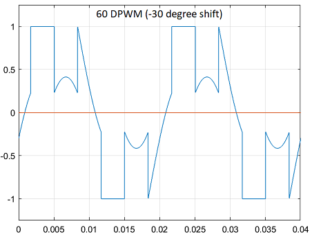
60 DPWM (-30 度シフト): 60 DPWM から -30 度シフト
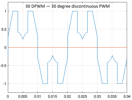
30 DPWM: 30 度の不連続 PWM
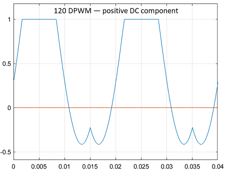
120 DPWM: 正の DC 成分
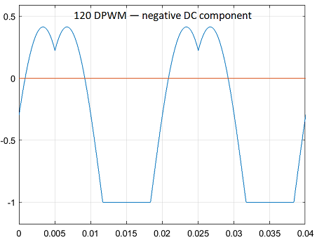
120 DPWM: 負の DC 成分
不連続 PWM (DPWM) の場合、ブロックは 1 相につき基本周期ごとに合計 120 度の変調波を正または負の DC レールに固定します。各固定区間は変調が不連続になります。
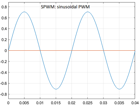
次の図は、正弦波 PWM (SPWM) の波形を示しています。
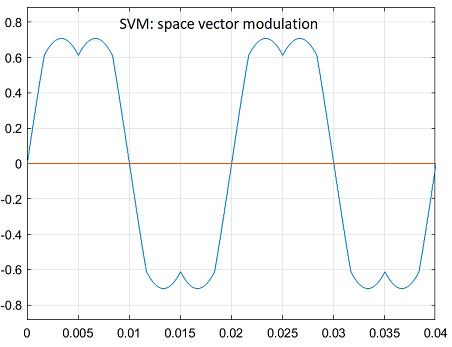
次の図は、空間ベクトル変調 (SVM) の波形を示しています。
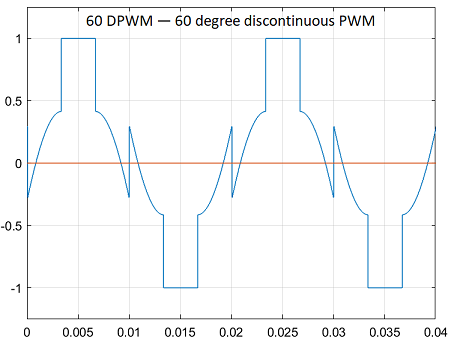
次の図は、基本周期ごとに 2 つの 60 度固定区間がある 60 度の DPWM の波形を示しています。
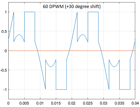
次の図は、30 度の正の位相シフトがある 60 度の DPWM の波形を示しています。
次の図は、30 度の負の位相シフトがある 60 度の DPWM の波形を示しています。
次の図は、基本周期ごとに 4 つの 30 度固定区間がある 30 度の DPWM の波形を示しています。
次の図は、正の DC 固定がある 120 度の DPWM の波形を示しています。
次の図は、負の DC 固定がある 120 度の DPWM の波形を示しています。
例

速度センサーを使用した誘導モーターのベクトル制御
この例では、三相交流誘導モーター (ACIM) の角速度を制御するためのベクトル制御 (FOC) 手法を実装します。この FOC アルゴリズムには回転子の速度フィードバックが必要であり、この例ではそれを直交エンコーダー センサーを使用して取得します。FOC の詳細については、ベクトル制御を参照してください。

ホール センサーを使用した PMSM のベクトル制御
この例では、三相永久磁石同期モーター (PMSM) の角速度を制御するためのベクトル制御 (FOC) 手法を実装します。この FOC アルゴリズムには回転子の位置フィードバックが必要であり、それをホール センサーで取得します。FOC の詳細については、ベクトル制御を参照してください。
端子
入力
出力
パラメーター
拡張機能
バージョン履歴
R2020a で導入