Bandstop FIR
Design bandstop finite impulse response filter
Description
A bandstop filter attenuates the energy of an input signal within a specified frequency range. A finite impulse response (FIR) filter computes an output signal as a running weighted average of input samples.
Signal Processing Toolbox™ provides different ways to design bandstop FIR filters:
designfiltfunction — Design a bandstop FIR filter at the command line or in a script. Use"bandstopfir"as the first argument when you call the function.For an example, see Design Bandstop FIR Filter Using designfilt.
Design Filter Live Editor task — Design a bandstop FIR filter as part of a live script. The task displays code that you can paste into other MATLAB® programs.
For an example, see Design Bandstop FIR Filter Using Live Editor Task.
Filter Designer app — Design a bandstop FIR filter interactively. Export your design to the MATLAB workspace, to Simulink®, or to a file.
For an example, see Design Bandstop FIR Filter Using Filter Designer.
All of these methods output digitalFilter objects. If
you have a DSP System Toolbox™ license, you can output your design as a filter System object™ and include additional Design Method Options.
For other ways to design bandstop FIR filters using MATLAB, see Other Bandstop FIR Filter Design Functions.
Examples
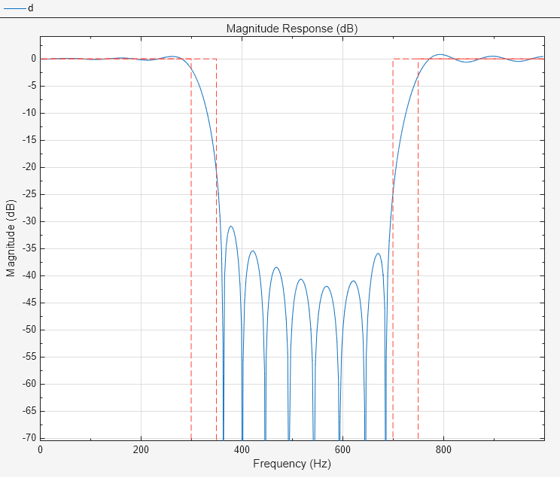
To design the filter at the command line or in a script, use the designfilt function with "bandstopfir" as first argument. Use name-value arguments to specify your design further.
d = designfilt("bandstopfir", ...                           % Filter type
    SampleRate=2000, ...                                    % Sample rate
    FilterOrder=40, ...                                     % Filter order
    PassbandFrequency1=300,StopbandFrequency1=350, ...      % Frequency constraints
    StopbandFrequency2=700,PassbandFrequency2=750, ...
    DesignMethod="ls", ...                                  % Design method
    PassbandWeight1=3,StopbandWeight=15,PassbandWeight2=1); % Design method options
filterAnalyzer(d)
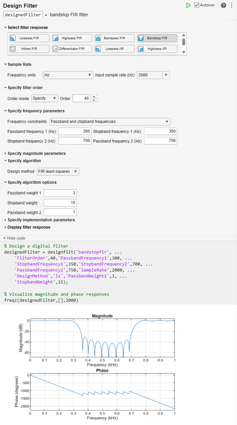
To design the filter using the Design Filter Live Editor task:
Specify the filter:
Under Select filter response, select Bandstop FIR.
Under Sample Rate, specify the Frequency units as
Hzand the Input sample rate (Hz) as2000.Under Specify filter order, set Order mode to
Specifyand enter a value of40.Under Specify frequency parameters, specify:
Passband frequency 1 as
300HzStopband frequency 1 as
350HzStopband frequency 2 as
700HzPassband frequency 2 as
750Hz
Under Specify algorithm, select
FIR
                        least-squares
. Under Specify algorithm options, specify:Passband weight 1 as
3Stopband weight as
15Passband weight 2 as
1
The Live Editor task updates the filter automatically by default.
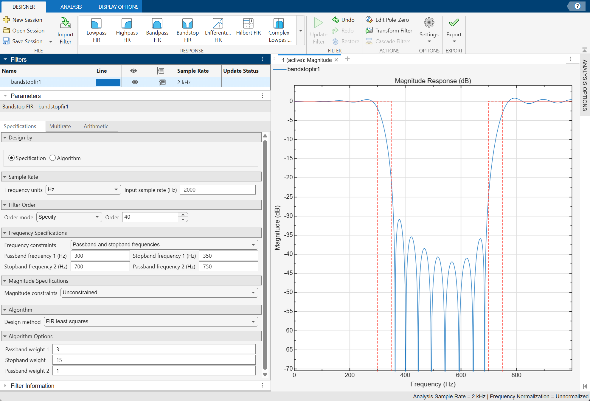
To design the filter using the Filter Designer app:
In the Response gallery of the Designer tab in the app toolstrip, select Bandstop FIR.
Specify the filter using the options in the Filter Parameters Table:
In Design by, select Specification.
In Sample Rate, specify the Frequency units as
Hzand the Input sample rate (Hz) as2000.Under Filter Order, set Order mode to
Specifyand enter a value of40.Under Frequency Specifications, specify:
Passband frequency 1 as
300HzStopband frequency 1 as
350HzStopband frequency 2 as
700HzPassband frequency 2 as
750Hz
Under Algorithm, select
FIR least-squares. Under Algorithm Options, specify:Passband weight 1 as
3Stopband weight as
15Passband weight 2 as
1
In the Filter section of the Designer tab, click Update Filter.
Export code to create your digital filter. On the toolstrip, click Export and select
Generate MATLAB function>Digital Filter Object. The code appears in the Editor.function designedFilter = bandstopfir1filt designedFilter = designfilt('bandstopfir', ... 'FilterOrder',40,'PassbandFrequency1',300, ... 'StopbandFrequency1',350,'StopbandFrequency2',700, ... 'PassbandFrequency2',750,'SampleRate',2000, ... 'DesignMethod','ls','PassbandWeight1',3, ... 'StopbandWeight',15); end
Parameters
Design Method
Specify the algorithm to design the filter. The available design methods correlate with the set of design specifications that you choose.
Design the filter using the Parks-McClellan algorithm. Equiripple filters have a frequency response that minimizes the maximum ripple magnitude over all bands.
designfilt Function | Design Filter Live Editor Task | Filter Designer App |
|---|---|---|
Specify
| In the Specify algorithm
section of the task, set Design
method to
| In the Algorithm section of
the filter parameters panel, set Design
method to
|
The equiripple design method supports these design parameter combinations.
| Filter Order | Frequency Specifications | Magnitude Specifications | Design Method Options | DSP System Toolbox License Required |
|---|---|---|---|---|
| N/A |
|
| N/A | |
| N/A |
|
|
| ✓ |
|
|
| N/A |
| |
|
|
| N/A |
| ✓ |
|
|
|
|
| ✓ |
Design the filter using the Kaiser window algorithm. The method truncates the impulse response of an ideal filter and uses a Kaiser window to attenuate the resulting truncation oscillations.
designfilt Function | Design Filter Live Editor Task | Filter Designer App |
|---|---|---|
Specify
| In the Specify algorithm
section of the task, set Design
method to | In the Algorithm section of
the filter parameters panel, set Design
method to |
The Kaiser window design method supports these design parameter combinations.
| Filter Order | Frequency Specifications | Magnitude Specifications | Design Method Options | DSP System Toolbox License Required |
|---|---|---|---|---|
| N/A |
|
|
|
Design the filter using the window algorithm. The method uses a least-squares approximation to compute the filter coefficients and then smooths the impulse response with Window.
designfilt Function | Design Filter Live Editor Task | Filter Designer App |
|---|---|---|
Specify
| In the Specify algorithm
section of the task, set Design
method to
| In the Algorithm section of
the filter parameters panel, set Design
method to
|
The window design method supports these design parameter combinations.
| Filter Order | Frequency Specifications | Magnitude Specifications | Design Method Options | DSP System Toolbox License Required |
|---|---|---|---|---|
|
|
|
N/A |
|
Design the filter using the constrained least squares algorithm. The method minimizes the discrepancy between a specified arbitrary piecewise-linear function and the magnitude response of the filter. At the same time, it lets you set constraints on the passband ripple and the stopband attenuation.
designfilt Function | Design Filter Live Editor Task | Filter Designer App |
|---|---|---|
Specify
| In the Specify algorithm
section of the task, set Design
method to | In the Algorithm section of
the filter parameters panel, set Design
method to |
The constrained least squares design method supports these design parameter combinations.
| Filter Order | Frequency Specifications | Magnitude Specifications | Design Method Options | DSP System Toolbox License Required |
|---|---|---|---|---|
|
|
|
|
|
Design the filter using the least squares algorithm. The method minimizes the discrepancy between a specified arbitrary piecewise-linear function and the filter’s magnitude response.
designfilt Function | Design Filter Live Editor Task | Filter Designer App |
|---|---|---|
Specify
| In the Specify algorithm
section of the task, set Design
method to | In the Algorithm section of
the filter parameters panel, set Design
method to |
The least squares design method supports these design parameter combinations.
| Filter Order | Frequency Specifications | Magnitude Specifications | Design Method Options | DSP System Toolbox License Required |
|---|---|---|---|---|
|
|
|
N/A |
|
Design the filter using the least Pth-norm unconstrained optimization algorithm.
You must have a DSP System Toolbox license to use this design method.
designfilt Function | Design Filter Live Editor Task | Filter Designer App |
|---|---|---|
Specify
| In the Specify algorithm
section of the task, set Design
method to | In the Algorithm section
of the filter parameters panel, set Design
method to |
The least Pth-norm method supports these design parameter combinations.
| Filter Order | Frequency Specifications | Magnitude Specifications | Design Method Options | DSP System Toolbox License Required |
|---|---|---|---|---|
|
|
|
N/A |
| ✓ |
Sample Rate
Specify the filter sample rate as a positive scalar expressed in hertz.
designfilt Function | Design Filter Live Editor Task | Filter Designer App |
|---|---|---|
| In the Sample Rate section of the task:
| In the Sample Rate section of the filter parameters panel:
|
Filter Order
Specify the filter order N as a positive integer. Some design methods let you specify the order. Others generate minimum-order designs, which are the shortest filters that satisfy the specified constraints.
designfilt Function | Design Filter Live Editor Task | Filter Designer App |
|---|---|---|
| In the Specify Filter Order section of the task:
| In the Filter Order section of the filter parameters panel:
|
Frequency Specifications
Specify the lower passband frequency as a positive scalar smaller than the Nyquist frequency. If you work with normalized frequencies, the Nyquist frequency is 1. If you specify a sample rate Fs , the Nyquist frequency is Fs/2.
The lower passband frequency is the highest frequency in the lower passband for which the magnitude response of the filter is within an interval of width Passband Ripple 1 about the reference value, usually 0 dB.
designfilt Function | Design Filter Live Editor Task | Filter Designer App |
|---|---|---|
|
|
|
Specify the lower cutoff frequency as a positive scalar smaller than the Nyquist frequency. If you work with normalized frequencies, the Nyquist frequency is 1. If you specify a sample rate Fs, the Nyquist frequency is Fs/2.
The lower cutoff frequency is the lowest frequency at which the magnitude
response of the filter is
mag2db(1/2)= 20 log10½ = –6.02
dB below the reference value, usually 0 dB.
designfilt Function | Design Filter Live Editor Task | Filter Designer App |
|---|---|---|
|
|
|
Specify the lower stopband frequency as a positive scalar smaller than the Nyquist frequency. If you work with normalized frequencies, the Nyquist frequency is 1. If you specify a sample rate Fs, the Nyquist frequency is Fs/2.
The lower stopband frequency is the lowest frequency in the stopband for which the magnitude response of the filter is at least Stopband Attenuation dB lower than the reference value, usually 0 dB.
designfilt Function | Design Filter Live Editor Task | Filter Designer App |
|---|---|---|
|
|
|
Specify the higher stopband frequency as a positive scalar smaller than the Nyquist frequency. If you work with normalized frequencies, the Nyquist frequency is 1. If you specify a sample rate Fs, the Nyquist frequency is Fs/2.
The higher stopband frequency is the highest frequency in the stopband for which the magnitude response of the filter is at least Stopband Attenuation dB lower than the reference value, usually 0 dB.
designfilt Function | Design Filter Live Editor Task | Filter Designer App |
|---|---|---|
|
|
|
Specify the higher cutoff frequency as a positive scalar smaller than the Nyquist frequency. If you work with normalized frequencies, the Nyquist frequency is 1. If you specify a sample rate Fs, the Nyquist frequency is Fs/2.
The higher cutoff frequency is the highest frequency at which the magnitude
response of the filter is
mag2db(1/2)= 20 log10½ = –6.02
dB below the reference value, usually 0 dB.
designfilt Function | Design Filter Live Editor Task | Filter Designer App |
|---|---|---|
|
|
|
Specify the higher passband frequency as a positive scalar smaller than the Nyquist frequency. If you work with normalized frequencies, the Nyquist frequency is 1. If you specify a sample rate F s , the Nyquist frequency is F s/2.
The higher passband frequency is the lowest frequency in the higher passband for which the magnitude response of the filter is within an interval of width Passband Ripple 2 about the reference value, usually 0 dB.
designfilt Function | Design Filter Live Editor Task | Filter Designer App |
|---|---|---|
|
|
|
Magnitude Specifications
Specify the lower passband ripple as a positive scalar in decibels.
The lower passband ripple measures the fluctuation of the gain of the filter in the lower passband about the reference value, usually 0 dB.
designfilt Function | Design Filter Live Editor Task | Filter Designer App |
|---|---|---|
|
|
|
Specify the stopband attenuation as a positive scalar in decibels.
The stopband attenuation measures the extent by which the filter gain in the stopband is decreased in comparison to the reference value, usually 0 dB.
designfilt Function | Design Filter Live Editor Task | Filter Designer App |
|---|---|---|
|
|
|
Specify the higher passband ripple as a positive scalar in decibels.
The higher passband ripple measures the fluctuation of the gain of the filter in the higher passband about the reference value, usually 0 dB.
designfilt Function | Design Filter Live Editor Task | Filter Designer App |
|---|---|---|
|
|
|
Use this argument to constrain the ripple in the lower passband for an Equiripple design.
designfilt Function | Design Filter Live Editor Task | Filter Designer App |
|---|---|---|
|
|
|
Use this argument to constrain the attenuation of the stopband for an Equiripple design.
designfilt Function | Design Filter Live Editor Task | Filter Designer App |
|---|---|---|
|
|
|
Use this argument to constrain the ripple in the higher passband for an Equiripple design.
designfilt Function | Design Filter Live Editor Task | Filter Designer App |
|---|---|---|
|
|
|
Design Method Options
Basic Options
Minimum order parity of a Kaiser Window design or an Equiripple design, specified as one of these:
Any — The returned filter can have even or odd order, whichever is smaller.
Even — The returned filter has the smallest possible even order.
Odd — The returned filter has the smallest possible odd order. This option is available only for equiripple designs.
You must have a DSP System Toolbox license to use this option with the equiripple method.
designfilt Function | Design Filter Live Editor Task | Filter Designer App |
|---|---|---|
|
|
|
Passband offset for a Constrained Least Squares design, specified as a positive scalar in decibels. This parameter specifies the filter gain in the passband.
Example: Setting this parameter to 0 results in a filter
with unit gain in the passband.
Example: Setting this parameter to 2 results in a filter
with a passband gain of 2 dB or 1.259.
designfilt Function | Design Filter Live Editor Task | Filter Designer App |
|---|---|---|
|
|
|
Lower passband optimization weight for an Equiripple, Least Squares, or Least Pth-Norm design, specified as a positive scalar.
Weights are a way of specifying the relative importance of the passband ripple and the stopband attenuation in a filter design. By default, the passband and the stopbands are equally weighted, each with unit weight. By increasing a passband weight, you can decrease the passband ripple at the expense of decreasing the stopband attenuation.
You must have a DSP System Toolbox license to use this option with some syntaxes.
designfilt Function | Design Filter Live Editor Task | Filter Designer App |
|---|---|---|
|
|
|
Higher passband optimization weight for an Equiripple, Least Squares, or Least Pth-Norm design, specified as a positive scalar.
Weights are a way of specifying the relative importance of the passband ripple and the stopband attenuation in a filter design. By default, the passband and the stopbands are equally weighted, each with unit weight. By increasing a passband weight, you can decrease the passband ripple at the expense of decreasing the stopband attenuation.
You must have a DSP System Toolbox license to use this option with some syntaxes.
designfilt Function | Design Filter Live Editor Task | Filter Designer App |
|---|---|---|
|
|
|
Scale passband when using the Kaiser Window design
method or the Window design
method, specified as a logical scalar. When you set this parameter to
true, the passband is scaled, after windowing, so that
the filter has unit gain at zero frequency.
designfilt Function | Design Filter Live Editor Task | Filter Designer App |
|---|---|---|
|
|
|
Stopband optimization weight for an Equiripple, Least Squares, or Least Pth-Norm design, specified as a positive scalar.
Weights are a way of specifying the relative importance of the passband ripple and the stopband attenuation in a filter design. By default, the passband and the stopbands are equally weighted, each with unit weight. By increasing the stopband weight, you can increase the attenuation of the stopband at the expense of increasing passband ripple.
You must have a DSP System Toolbox license to use this option with some syntaxes.
designfilt Function | Design Filter Live Editor Task | Filter Designer App |
|---|---|---|
|
|
|
Window used by the Window algorithm, specified as one of these:
Hamming (@
hamming)Hann (@
hann)Kaiser (@
kaiser) — Specify the shape factor as a positive real scalar.Rectangular (@
rectwin)Chebyshev (@
chebwin) — Specify the sidelobe magnitude factor as a positive scalar in decibels.Bartlett (@
bartlett)Blackman (@
blackman)Flat top (@
flattopwin)Gaussian (@
gausswin) — To use a Gaussian window with a width factor α ≠ 2.5 in the Filter Designer app or the Design Filter Live Editor task, specify it as a custom window.Nuttall (@
nuttallwin)Triangular (@
triang)Custom — Specify a custom window as a vector of length N + 1, where N is the Filter Order. You can also specify the custom window as a function name or a function handle with N + 1 as first input. Additional inputs can be passed by specifying a cell array.
Example:
hann(N+1) and
(1-cos(2*pi*(0:N)'/N))/2 both specify a Hann window to use with a
filter of order N.
Example:
"hamming" specifies a Hamming window of the required
order.
Example:
@hann specifies a Hann window of the required
order.
Example:
{@kaiser,0.5} specifies a Kaiser window of the required
order with shape parameter 0.5.
designfilt Function | Design Filter Live Editor Task | Filter Designer App |
|---|---|---|
|
|
|
Zero phase for a Constrained Least Squares design,
specified as logical scalar. When you set this parameter to
true, the zero-phase response of the filter is always
positive, enabling you to perform spectral factorization on the result and
obtain a minimum-phase filter from it.
designfilt Function | Design Filter Live Editor Task | Filter Designer App |
|---|---|---|
|
|
|
Advanced Options
Density of the frequency grid used by the Least Pth-Norm algorithm, specified as a positive scalar ≥ 10. The frequency grid has roughly (Density Factor × Filter Order)/(2 × Passband Frequency) frequency points. Increasing the density factor results in filters that more closely match an equiripple filter but take longer to compute.
You must have a DSP System Toolbox license to use this option. This parameter is available only in the
designfilt function.
designfilt Function | Design Filter Live Editor Task | Filter Designer App |
|---|---|---|
|
N/A |
N/A |
Initial Pth norm used by the Least Pth-Norm algorithm, specified as a positive scalar. Starting the optimization with a smaller initial value aids in the convergence of the algorithm. For more information, see Least Pth-Norm Optimal IIR Filter Design.
You must have a DSP System Toolbox license to use this option. This parameter is available only in the
designfilt function.
designfilt Function | Design Filter Live Editor Task | Filter Designer App |
|---|---|---|
|
N/A |
N/A |
Initial estimate of the filter numerator coefficients for the Least Pth-Norm algorithm, specified as a vector of size (N+1)-by-1, where N is the Filter Order that you specify.
You must have a DSP System Toolbox license to use this option. This parameter is available only in the
designfilt function.
designfilt Function | Design Filter Live Editor Task | Filter Designer App |
|---|---|---|
|
N/A |
N/A |
L-infinity norm used by the Least Pth-Norm algorithm, specified as a positive scalar.
You must have a DSP System Toolbox license to use this option.
designfilt Function | Design Filter Live Editor Task | Filter Designer App |
|---|---|---|
|
|
|
Phase constraint for an Equiripple or Least Pth-Norm design, specified as one of these options:
Linear — Design a linear-phase equiripple FIR filter.
Minimum — Design a minimum-phase equiripple FIR filter.
Maximum — Design a maximum-phase equiripple FIR filter.
You must have a DSP System Toolbox license to use this option.
designfilt Function | Design Filter Live Editor Task | Filter Designer App |
|---|---|---|
|
|
|
More About
Use one these functions to design a bandstop FIR filter:
fir1— Window-based FIR filter designfir2— Frequency sampling-based FIR filter designfirls— Least-squares linear-phase FIR filter designfircls— Constrained-least-squares FIR multiband filter designfirpm— Parks-McClellan optimal FIR filter designcfirpm— Complex and nonlinear-phase equiripple FIR filter designfirgr— Generalized Remez FIR filter designfirlpnorm— Least P-norm optimal FIR filterdesignBandstopFIR— Design and implement bandstop FIR filter
Use this function to bandstop-filter a signal:
bandstop— Bandstop-filter signals
See Also
Apps
Functions
Live Editor Tasks
MATLAB Command
You clicked a link that corresponds to this MATLAB command:
Run the command by entering it in the MATLAB Command Window. Web browsers do not support MATLAB commands.
Web サイトの選択
Web サイトを選択すると、翻訳されたコンテンツにアクセスし、地域のイベントやサービスを確認できます。現在の位置情報に基づき、次のサイトの選択を推奨します:
また、以下のリストから Web サイトを選択することもできます。
最適なサイトパフォーマンスの取得方法
中国のサイト (中国語または英語) を選択することで、最適なサイトパフォーマンスが得られます。その他の国の MathWorks のサイトは、お客様の地域からのアクセスが最適化されていません。
南北アメリカ
- América Latina (Español)
- Canada (English)
- United States (English)
ヨーロッパ
- Belgium (English)
- Denmark (English)
- Deutschland (Deutsch)
- España (Español)
- Finland (English)
- France (Français)
- Ireland (English)
- Italia (Italiano)
- Luxembourg (English)
- Netherlands (English)
- Norway (English)
- Österreich (Deutsch)
- Portugal (English)
- Sweden (English)
- Switzerland
- United Kingdom (English)