estimateCameraParameters
Calibrate a single or stereo camera
Syntax
Description
[
returns an object cameraParams
,imagesUsed
,estimationErrors
]
= estimateCameraParameters(imagePoints
,worldPoints
)cameraParams
, containing estimates for
the intrinsic and extrinsic parameters and the distortion coefficients of a
single and stereo camera. The function also returns the images you used to
estimate the camera parameters and the standard estimation errors for the single
camera calibration. The estimateCameraParameters
function
estimates extrinsic and intrinsic parameters.
[
returns stereoParams
,pairsUsed
,estimationErrors
]
= estimateCameraParameters(imagePoints
,worldPoints
)stereoParams
, a stereoParameters
object
containing the parameters of the stereo camera. The function also returns the
images you used to estimate the stereo parameters and the standard estimation
errors for the stereo camera calibration.
configures the cameraParams
= estimateCameraParameters(___,Name,Value
)cameraParams
object properties specified by
one or more Name,Value
arguments, using any of the
preceding syntaxes. Unspecified properties have their default values.
Examples
Single Camera Calibration
Create a set of calibration images.
imds = imageDatastore(fullfile(toolboxdir('vision'),'visiondata',... 'calibration','mono')); imageFileNames = imds.Files;
Detect the calibration pattern.
[imagePoints, boardSize] = detectCheckerboardPoints(imageFileNames);
Generate the world coordinates of the corners of the squares.
squareSizeInMM = 29;
worldPoints = patternWorldPoints("checkerboard",boardSize,squareSizeInMM);
Calibrate the camera.
I = preview(imds); imageSize = [size(I, 1),size(I, 2)]; params = estimateCameraParameters(imagePoints,worldPoints, ... 'ImageSize',imageSize);
Visualize the calibration accuracy.
showReprojectionErrors(params);
Visualize camera extrinsics.
figure; showExtrinsics(params);
drawnow;
Plot detected and reprojected points.
figure; imshow(imageFileNames{1}); hold on; plot(imagePoints(:,1,1), imagePoints(:,2,1),'go'); plot(params.ReprojectedPoints(:,1,1),params.ReprojectedPoints(:,2,1),'r+'); legend('Detected Points','ReprojectedPoints'); hold off;
Perform Stereo Camera Calibration
Specify calibration images.
leftImages = imageDatastore(fullfile(toolboxdir("vision"),"visiondata", ... "calibration","stereo","left")); rightImages = imageDatastore(fullfile(toolboxdir("vision"),"visiondata", ... "calibration","stereo","right"));
Detect the checkerboards.
[imagePoints,boardSize] = ...
detectCheckerboardPoints(leftImages.Files,rightImages.Files);
Specify the world coordinates of the checkerboard keypoints. Square size is in millimeters.
squareSize = 108;
worldPoints = patternWorldPoints("checkerboard",boardSize,squareSize);
Calibrate the stereo camera system. Both cameras have the same resolution.
I = readimage(leftImages,1); imageSize = [size(I,1) size(I,2)]; params = estimateCameraParameters(imagePoints,worldPoints, ... "ImageSize",imageSize);
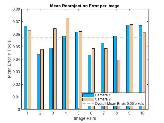
Visualize the calibration accuracy.
showReprojectionErrors(params)
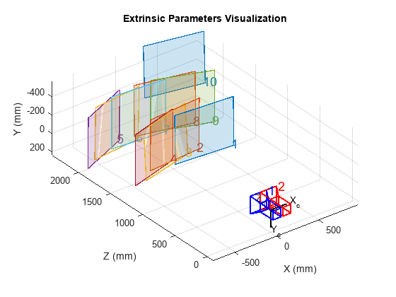
Visualize camera extrinsics.
figure showExtrinsics(params)
Convert to structure.
paramsStruct = toStruct(params)
paramsStruct = struct with fields:
CameraParameters1: [1x1 struct]
CameraParameters2: [1x1 struct]
RotationOfCamera2: [3x3 double]
TranslationOfCamera2: [-119.8720 -0.4005 -0.0258]
Version: [1x1 struct]
RectificationParams: [1x1 struct]
Estimate Camera Parameters Using Circle Grid
Create a set of calibration images.
imds = imageDatastore(fullfile(toolboxdir('vision'),'visiondata',... 'calibration','circleGrid','mono')); calibrationImages = readall(imds); calibrationImages = cat(4,calibrationImages{:});
Define the circle grid pattern dimensions.
patternDims = [8 11];
Detect the pattern in the calibration images.
imagePoints = detectCircleGridPoints(calibrationImages, patternDims,... 'PatternType','symmetric');
Specify the world coordinates for the circle grid keypoints. Center distance is in millimeters.
centerDistance = 18;
worldPoints = patternWorldPoints('circle-grid-symmetric',patternDims,centerDistance);
Calibrate the camera using the calibration images.
imageSize = size(calibrationImages,1:2); params = estimateCameraParameters(imagePoints,worldPoints,... 'ImageSize',imageSize);
Plot the detected pattern grid and the reprojected points.
figure imshow(calibrationImages(:,:,:,1)) hold on plot(imagePoints(:,1,1), imagePoints(:,2,1),'gx','MarkerSize',8) plot(params.ReprojectedPoints(:,1,1),params.ReprojectedPoints(:,2,1),'r+','MarkerSize',8) legend('Detected Points','ReprojectedPoints') hold off
Input Arguments
imagePoints
— Key points of calibration pattern
M-by-2-by-numImages | M-by-2-by-numPairs-by-2
array
Key points of calibration pattern, specified as an array of [x,y] intrinsic image coordinates.
Calibration | Input Array of [x,y] Key Points |
---|---|
Single Camera | M-by-2-by-numImages array of [x,y] points.
Partially detected patterns
are only supported for single camera calibration. To
include partially detected patterns in the estimate, use
[ |
Stereo Camera | M-by-2-by-numPairs-by-2 array of [x,y] points.
|
Data Types: single
| double
worldPoints
— Key points of calibration pattern in world coordinates
M-by-2 array
Key points of calibration pattern in world coordinates, specified as an M-by-2 array of M number of [x,y] world coordinates. The pattern must be planar; therefore, z-coordinates are zero. Calibration images must not be coplanar. Use only one calibration image per spatial plane.
Data Types: single
| double
Name-Value Arguments
Specify optional pairs of arguments as
Name1=Value1,...,NameN=ValueN
, where Name
is
the argument name and Value
is the corresponding value.
Name-value arguments must appear after other arguments, but the order of the
pairs does not matter.
Before R2021a, use commas to separate each name and value, and enclose
Name
in quotes.
Example: "WorldUnits","mm"
sets the world point units to
millimeters.
WorldUnits
— World points units
"mm"
(default) | character vector | string scalar
World points units, specified as a character vector or string scalar.
EstimateSkew
— Estimate skew
false
(default) | true
Estimate skew, specified as a logical scalar. When you set this property to
true
, the function estimates the image axes skew.
When set to false
, the image axes are exactly
perpendicular and the function sets the skew to zero.
NumRadialDistortionCoefficients
— Number of radial distortion coefficients
2
(default) | 3
Number of radial distortion coefficients to estimate, specified as the value
2
or 3
.
Radial distortion is the displacement of image points along radial lines extending from the principal point.
As image points move away from the principal point (positive radial displacement), image magnification decreases and a pincushion-shaped distortion occurs on the image.
As image points move toward the principal point (negative radial displacement), image magnification increases and a barrel-shaped distortion occurs on the image.
The radial distortion coefficients model this type of distortion. The distorted points are denoted as (xdistorted, ydistorted):
xdistorted = x(1 + k1*r2 + k2*r4 + k3*r6)
ydistorted= y(1 + k1*r2 + k2*r4 + k3*r6)
x, y — Undistorted pixel locations. x and y are in normalized image coordinates. Normalized image coordinates are calculated from pixel coordinates by translating to the optical center and dividing by the focal length in pixels. Thus, x and y are dimensionless.
k1, k2, and k3 — Radial distortion coefficients of the lens.
r2 = x2 + y2
Typically, two coefficients are sufficient for calibration. For severe distortion, such as in wide-angle lenses, you can select three coefficients to include k3.
EstimateTangentialDistortion
— Tangential distortion flag
false
(default) | true
Tangential distortion flag, specified as a logical scalar. When you set this property to
true
, the function estimates the tangential
distortion. When you set it to false
, the tangential
distortion is negligible.
Tangential distortion occurs when the lens and the image plane are not parallel. The tangential distortion coefficients model this type of distortion.
The distorted points are denoted as (xdistorted, ydistorted):
xdistorted = x + [2 * p1 * x * y + p2 * (r2 + 2 * x2)]
ydistorted = y + [p1 * (r2 + 2 *y2) + 2 * p2 * x * y]
x, y — Undistorted pixel locations. x and y are in normalized image coordinates. Normalized image coordinates are calculated from pixel coordinates by translating to the optical center and dividing by the focal length in pixels. Thus, x and y are dimensionless.
p1 and p2 — Tangential distortion coefficients of the lens.
r2 = x2 + y2
InitialK
— Initial guess for camera intrinsics
[]
(default) | 3-by-3 matrix
Initial guess for camera intrinsics, specified as a 3-by-3 matrix. The matrix has this format:
The coordinates [cx
cy] represent the optical center (the principal
point), in pixels. When the x- and y-axes are exactly
perpendicular, the skew parameter s equals 0
.
fx = F*sx
fy = F*sy
F is the focal length in world units, typically expressed in millimeters.
sx and sy are the number of pixels per world unit in the x- and y-direction respectively.
fx and fy are expressed in pixels.
If you do not provide an initial value, the function computes the initial intrinsic matrix using linear least squares.
InitialRadialDistortion
— Initial guess for radial distortion coefficients
[]
(default) | 2-element vector | 3-element vector
Initial guess for radial distortion coefficients, specified as a 2- or 3-element vector. If
you do not provide an initial value, the function uses
0
as the initial value for all the
coefficients.
ImageSize
— Image size produced by camera
1-by-2 [mrows, ncols]
vector | []
Image size produced by camera, specified as a 1-by-2 [mrows, ncols] vector.
Output Arguments
cameraParams
— Camera parameters
cameraParameters
object
Camera parameters, returned as a cameraParameters
object.
imagesUsed
— Images used to estimate camera parameters
numImages-by-1 logical array
Images you use to estimate camera parameters, returned as a numImages-by-1
logical array. numImages corresponds to the number of
images. The array indicates which images you used to estimate the camera
parameters. A logical true
value in the array indicates
which images you used to estimate the camera parameters.
The function computes a homography between the world points
and the points detected in each image. If the homography computation
fails for an image, the function issues a warning. The points for
that image are not used for estimating the camera parameters. The
function also sets the corresponding element of imagesUsed
to false
.
estimationErrors
— Standard errors of estimated parameters
cameraCalibrationErrors
object | stereoCalibrationErrors
object
Standard errors of estimated parameters, returned as a cameraCalibrationErrors
object or a stereoCalibrationErrors
object.
stereoParams
— Camera parameters for stereo system
stereoParameters
object
Camera parameters for stereo system, returned as a stereoParameters
object. The
object contains the intrinsic, extrinsic, and lens distortion parameters of
the stereo camera system.
pairsUsed
— Image pairs used to estimate stereo camera parameters
numPairs-by-1 logical array
Image pairs used to estimate camera parameters, returned as a
numPairs-by-1 logical array.
numPairs corresponds to the number of image pairs. A
logical true
value in the array indicates which image
pairs you used to estimate the camera parameters.
Algorithms
Calibration Algorithm
You can use the Camera Calibrator app with cameras up to a field of view (FOV) of 95 degrees. The calibration algorithm assumes a pinhole camera model.
This equation provides the transformation that relates a world coordinate [X Y Z] and the corresponding image point [x y]:
w: arbitrary scale factor
K: camera intrinsic matrix
R: matrix representing the 3-D rotation of the camera
t: translation of the camera relative to the world coordinate system
Camera calibration estimates the values of the intrinsic parameters, the extrinsic parameters, and the distortion coefficients. There are two steps involved in camera calibration:
Solve for the intrinsics and extrinsics in closed form, assuming that lens distortion is zero. [1]
Estimate all parameters simultaneously including the distortion coefficients using nonlinear least-squares minimization (Levenberg–Marquardt algorithm). Use the closed form solution from the preceding step as the initial estimate of the intrinsics and extrinsics. Then set the initial estimate of the distortion coefficients to zero. [1][2]
References
[1] Zhang, Z. "A Flexible New Technique for Camera Calibration." IEEE Transactions on Pattern Analysis and Machine Intelligence 22, no. 11 (November 2000): 1330–34. https://doi.org/10.1109/34.888718.
[2] Heikkila, J., and O. Silven. “A Four-Step Camera Calibration Procedure with Implicit Image Correction.” In Proceedings of IEEE Computer Society Conference on Computer Vision and Pattern Recognition, 1106–12. San Juan, Puerto Rico: IEEE Comput. Soc, 1997. https://doi.org/10.1109/CVPR.1997.609468.
[3] Bouguet, J.Y. “Camera Calibration Toolbox for Matlab”, Computational Vision at the California Institute of Technology.
[4] Bradski, G., and A. Kaehler. Learning OpenCV : Computer Vision with the OpenCV Library. Sebastopol, CA: O'Reilly, 2008.
Version History
Introduced in R2014bR2022b: Supports premultiply geometric transformation convention
Starting in R2022b, most Computer Vision Toolbox™ functions create and perform geometric transformations using the
premultiply convention. Accordingly, to specify an initial guess for camera
intrinsics in the premultiply convention, use the new InitialK
name-value argument.
Although you can still specify an initial guess for camera intrinsics using the
InitialIntrinsicMatrix
name-value argument, this argument is
not recommended because it uses the postmultiply convention. You can streamline your
geometric transformation workflows by switching to the premultiply geometric
transformation convention. For more information, see Migrate Geometric Transformations to Premultiply Convention.
See Also
Apps
Objects
Functions
showReprojectionErrors
|showExtrinsics
|undistortImage
|undistortPoints
|detectCheckerboardPoints
|generateCheckerboardPoints
|patternWorldPoints
|reconstructScene
|rectifyStereoImages
|disparityBM
|disparitySGM
|estimateStereoRectification
|estimateFundamentalMatrix
|estimateStereoBaseline
MATLAB Command
You clicked a link that corresponds to this MATLAB command:
Run the command by entering it in the MATLAB Command Window. Web browsers do not support MATLAB commands.
Select a Web Site
Choose a web site to get translated content where available and see local events and offers. Based on your location, we recommend that you select: .
You can also select a web site from the following list
How to Get Best Site Performance
Select the China site (in Chinese or English) for best site performance. Other MathWorks country sites are not optimized for visits from your location.
Americas
- América Latina (Español)
- Canada (English)
- United States (English)
Europe
- Belgium (English)
- Denmark (English)
- Deutschland (Deutsch)
- España (Español)
- Finland (English)
- France (Français)
- Ireland (English)
- Italia (Italiano)
- Luxembourg (English)
- Netherlands (English)
- Norway (English)
- Österreich (Deutsch)
- Portugal (English)
- Sweden (English)
- Switzerland
- United Kingdom (English)
Asia Pacific
- Australia (English)
- India (English)
- New Zealand (English)
- 中国
- 日本Japanese (日本語)
- 한국Korean (한국어)