逆運動学
逆運動学 (IK) は、目的のエンドエフェクト位置を実現するために、ロボット モデルのジョイント コンフィギュレーションを決定します。ロボットの運動学的拘束は、ジョイント間の変換に基づいて rigidBodyTree ロボット モデル内に指定します。汎用逆運動学 (GIK) を使用して、カメラ アームの照準拘束または特定の剛体リンクの直交座標境界ボックスなどの拘束を満たすコンフィギュレーションを解決できます。"GIK ロボット拘束" オブジェクトを使用してこれらの拘束に対するパラメーターを指定し、generalizedInverseKinematics オブジェクトに渡します。
逆運動学の詳細については、逆運動学とはのページを参照してください。
アプリ
| 逆運動学デザイナー | Design inverse kinematics solvers, configurations, and waypoints (R2022a 以降) |
関数
ブロック
| Inverse Kinematics | エンドエフェクタの姿勢を実現するジョイント コンフィギュレーションの計算 |
トピック
- 逆運動学のアルゴリズム
逆運動学ソルバーのアルゴリズムとソルバー パラメーターの説明
- Inverse Kinematics for Robots with Floating Base
Calculate inverse kinematics for floating-base systems such as manipulators in space. (R2024a 以降)
- 逆運動学による軌跡制御モデリング
Simulink® の Inverse Kinematics ブロックを使用して、指定された軌跡に沿ってマニピュレーターを駆動する。
注目の例
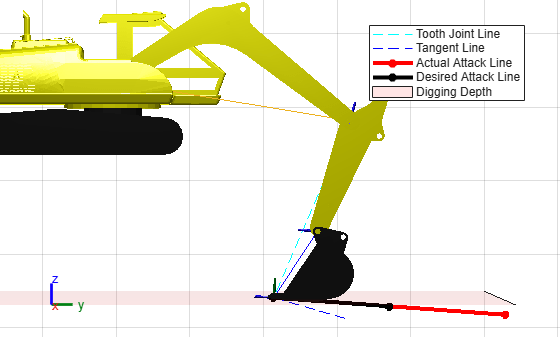
Constrain Links of Excavator for Earth Moving
Solve joint angles for excavator digging, grading, and unloading trajectories with GIK.

逆運動学を使用した 2 次元パスのトレース
単純な 2 次元マニピュレーターの逆運動学の計算

Solve Inverse Kinematics for Closed Loop Linkages
Model closed-loop linkages like four-bar systems using constraints with an inverse kinematics solver.
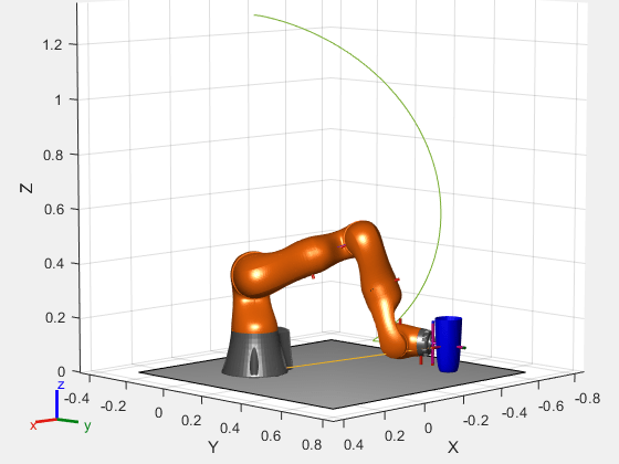
複数の運動学的拘束をもつリーチ軌跡の計画
汎用逆運動学を使用して、グリッパーの正確な接近に拘束があるマニピュレーターの軌跡を計画する。

Plan Manipulator Path for Dispensing Task Using Inverse Kinematics Designer
Design a collision-free manipulator path for adhesive dispensing using Inverse Kinematics Designer app.
授業用リソース

ロボット マニピュレーター
座標系の変換、DH パラメーター、順運動学/逆運動学を通じてロボット アームの動作の概念を学習する。