Main Content

Inverse Kinematics Designer

Design inverse kinematics solvers, configurations, and waypoints

Since R2022a

Description

The Inverse Kinematics Designer enables you to design an inverse kinematics solver for a URDF robot model. You can adjust the inverse kinematics solver and add constraints to achieve the desired behavior. Using this app you can:

  • Import URDF robot models from URDF files or the MATLAB Workspace.

  • Adjust inverse kinematics solvers and constraints.

  • Create joint configurations and export waypoints.

  • Export solver settings, constraints, and joint configurations to the MATLAB® workspace.

Inverse Kinematics Designer app

Open the Inverse Kinematics Designer App

  • MATLAB Toolstrip: On the Apps tab, under Robotics And Autonomous Systems, click Inverse Kinematics Designer Inverse Kinematics Designer icon.

  • MATLAB command prompt: Enter inverseKinematicsDesigner.

Examples

expand all

This example shows how to create, load, and save an Inverse Kinematics Designer session in addition to loading a robot into the session. The completed file is attached for reference as iksessiondata.mat. Load the session with the inverseKinematicsDesigner function or follow along with this example to create it.

Create Session

Open Inverse Kinematics Designer by using the inverseKinematicsDesigner function.

inverseKinematicsDesigner

Load Robot into Session

Use loadrobot from the Command Window to load a rigidBodyTree such as a Universal UR5e into the Workspace. importrobot can also be used to import a rigidBodyTree object from any robot URDF file.
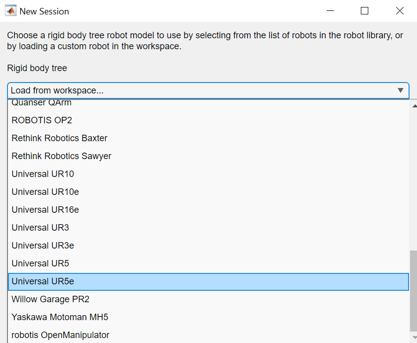
uniUR5e = loadrobot("universalUR5e");

Click New Session and select uniUR5e from the table in the dialog and click OK. This table contains all of the rigidBodyTree objects in the workspace. If you do not see your object in the table, verify that it is in your workspace and click Refresh.

Alternatively, you can load a robot by selecting from a list of robot models that come with the Robotics System Toolbox™ using the Rigid body tree drop down dialog and clicking OK.

Load robot from provided model library

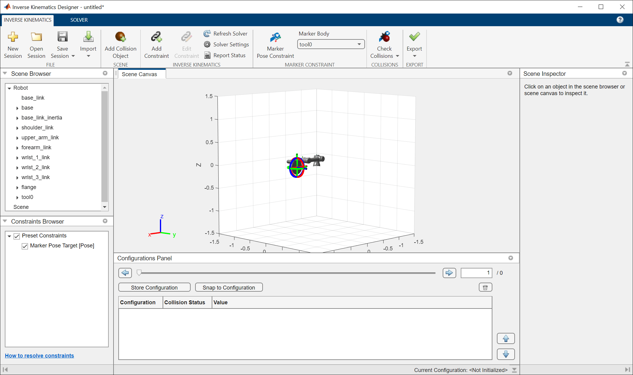
The Scene Canvas now contains the robot model, and the Scene Browser now displays all of the rigid bodies of the robot.

Add Collision Objects

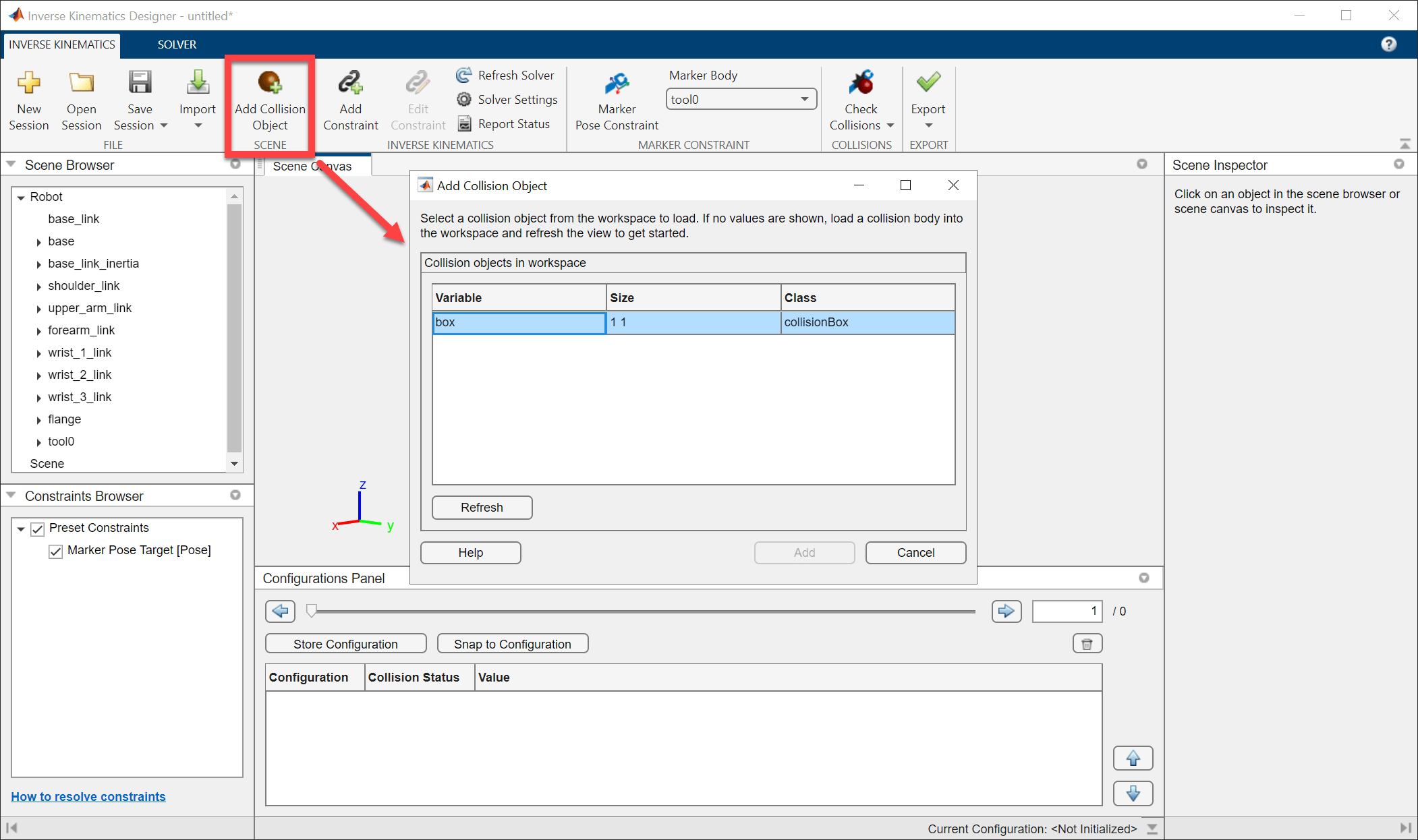
To add a collision object into the Scene Canvas, a collision object must be in the Workspace. For convenience, this example provides a simple box to use. For more information about creating collision objects, see collisionMesh, collisionBox, collisionSphere, and collisionCylinder.

Load the collisionobject MAT file which will save a collisionBox named box to your Workspace. Click Add Collision Object, and select box, from the table. Click OK to add it to the Scene Canvas.

The Scene Canvas now contains both the robot and the collision object. We will keep the object in this example, but if you want to delete the collision object, find the collision object in the Scene Browser under Scene, right-click the name of the collision object and click Delete.

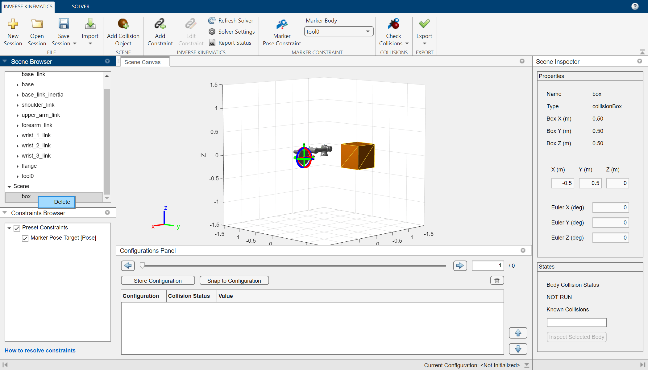
The position and Euler orientation of the object can viewed using the Scene Inspector when the object is selected in either the Scene Canvas or Scene Browser. The properties listed will change depending on the type of the collision object selected.
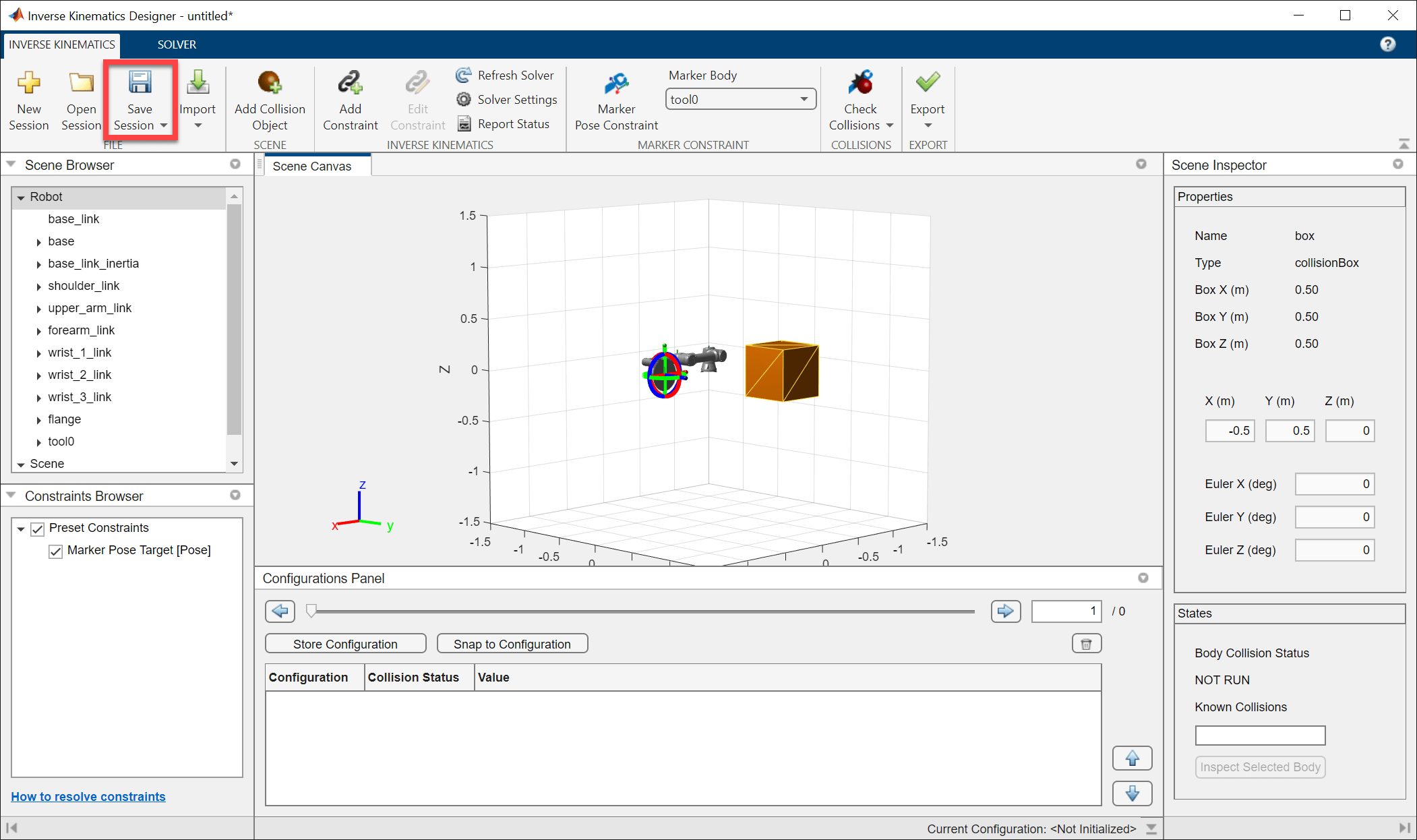
Save Session

To save this session, click Save Session. If this is the first time saving the session, name the file and select a location to save it. The file will be saved as a MAT (*.mat) file containing all session data and settings.
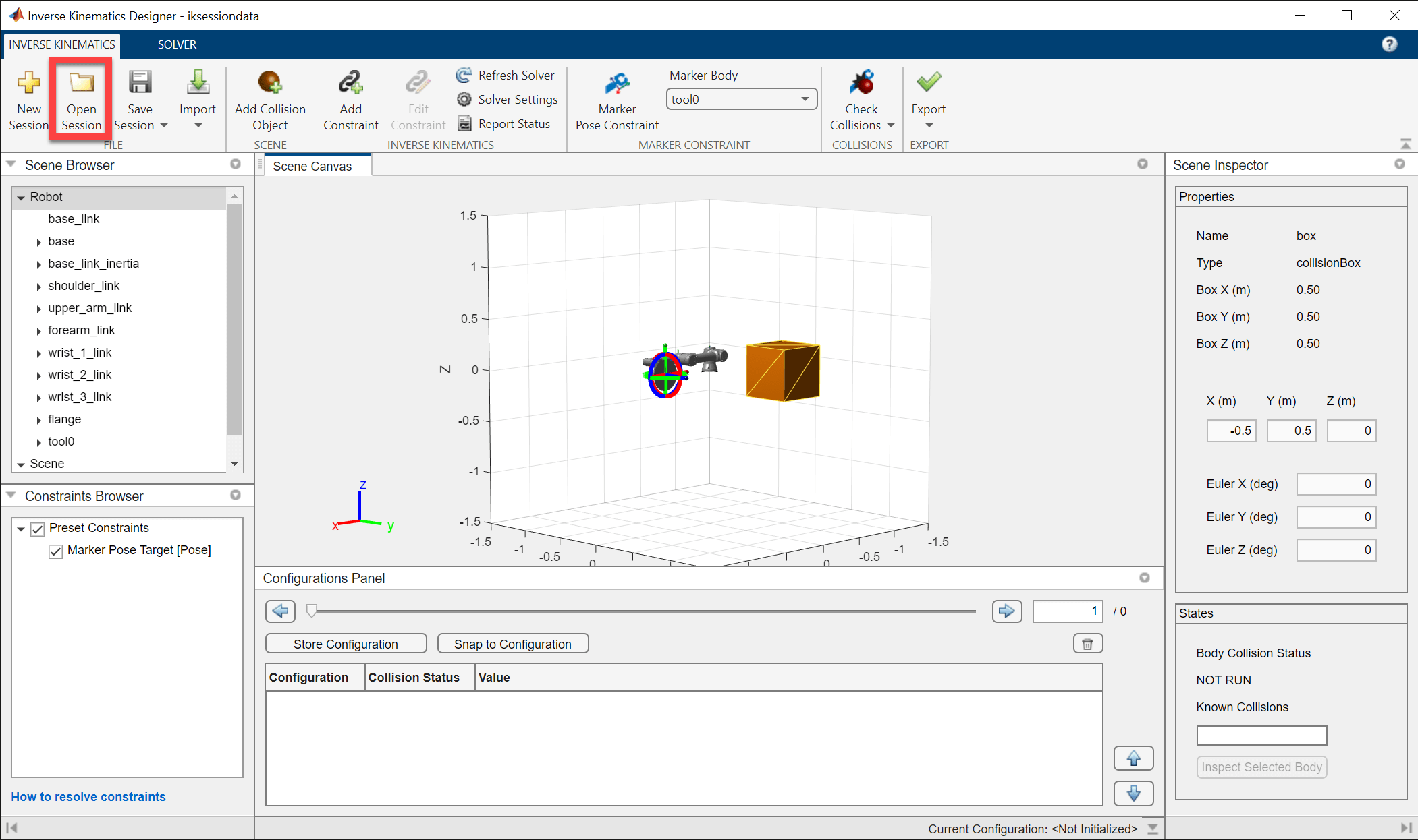
Load Saved Session

To load a session file, click Open Session from the Inverse Kinematics Designer app or specify the MAT file as a string to the inverseKinematicsDesigner. An example of this session has been provided in this example as iksessiondata.mat.

inverseKinematicsDesigner("iksessiondata.mat")

This example shows how to use the Scene Canvas and move a robot in it using the Inverse Kinematics Designer app.

Load an existing session (iksessiondata.mat) or refer to the Create Inverse Kinematics Designer Session example to create a session.

inverseKinematicsDesigner

Scene Canvas Controls

Use the axes toolbar in the Scene Canvas to control the view.

To rotate the Scene Canvas, select the Rotate 3D button and click and drag within the scene.

Click the Pan button and click and drag within the scene to pan within the Scene Canvas.

Select the Zoom In, or Zoom Out buttons and click and drag up or down to zoom in or out of an area within the Scene Canvas respectively.

Click the Restore View button to revert to the original default view.

Move Robot

Move the robot using constraints such as the preset Marker Pose Target constraint. The Marker Pose Target constraint is the simplest constraint to use to move the robot. This constraint sets a target pose on the last body in the robot model. In this case the marker body is set to tool0. The marker is visualized on top of the selected marker body with the red, green, and blue linear and circular indicators in the Scene Canvas. Clicking and dragging the linear or circular indicators will change the target position and Euler orientation respectively. The colors correspond to the axes colors indicated in the bottom left of the Scene Canvas.

moverobot_ikd.gif

Click Marker Pose Constraint to open the Constraint tab. From the Constraint tab, set Cartesian position in meters, Euler orientation in degrees, and the weights and tolerances of the position and orientation. The marker body can be changed in either the Constraint tab under End Effector Body list or in the Marker Body list in the Inverse Kinematics tab. Click Apply to save any changes, and click Close Constraint to exit the Constraint tab. Note that the specified Euler angles are computed using XYZ sequence.

The Marker Pose Target constraint can also be toggled on or off by using clearing or selecting the check box next to the Marker Pose Target constraint in the Constraints Browser.

Solution Details

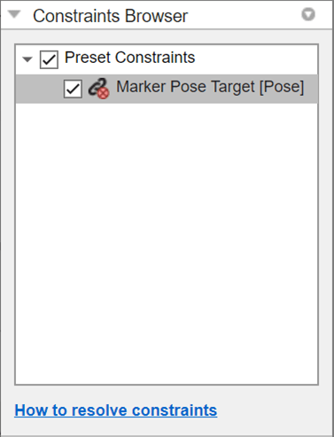
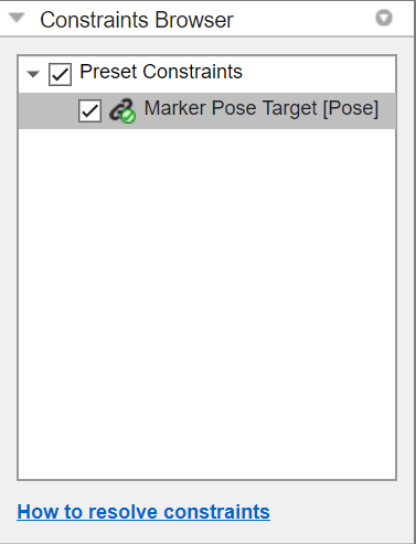
When the Marker Pose Target is moved, it sets the target pose and the inverse kinematics solver solves for a configuration where the selected marker body reaches the target pose. If it cannot find a solution to the target pose, the robot will move to the best available solution and the marker body will not move to the Marker Pose Target. This kind of solution can be identified visually by the constraint icon in the Constraints Browser. The icon with red x shows that the constraint is not met, while the green check shows that the constraint is being met.

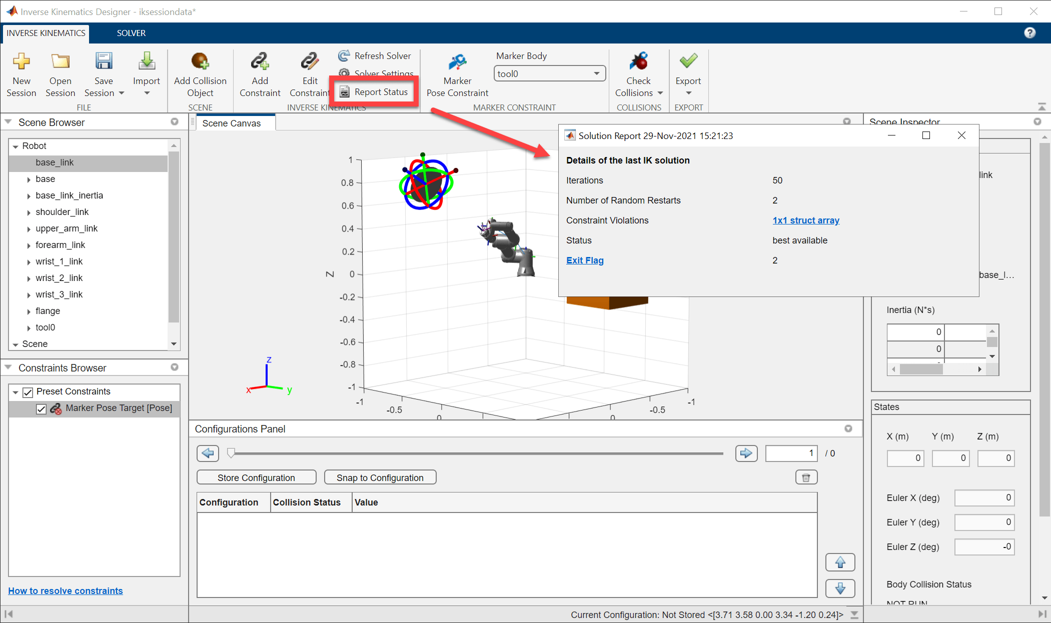
To find more information about why the solver failed to reach the solution, click the Report Status to see the details of the solver's solution. The number of Iterations and Number of Random Restarts list the number of times that the solver executed each respectively. The Constraints Violations shows structure array of all the conflicts that can be displayed in the command window. The status will show success if the solver successfully solves for the target pose, or best available if the solver is showing the best available solution it found if it could not reach the target pose. Exit Flag provides more detail on the execution of the specific solver algorithm. See Inverse Kinematics Algorithms for more information about the different exit flag types.

To troubleshoot why a solver failed to reach a solution, see Resolving Constraint Conflict for some tips.

This example shows how to use Inverse Kinematics Designer to create joint configurations and check for collisions using the Scene Inspector. This example uses data and skills from Create Inverse Kinematics Designer Session, and Use Scene Canvas and Move Robot. Refer to those examples before continuing.

Load Session

Use inverseKinematicsDesigner with the iksessiondata.mat session file to load a robot with a basic collision object in the scene.

inverseKinematicsDesigner

Create Configurations

Use the Configurations Panel to create, modify, and view configurations.

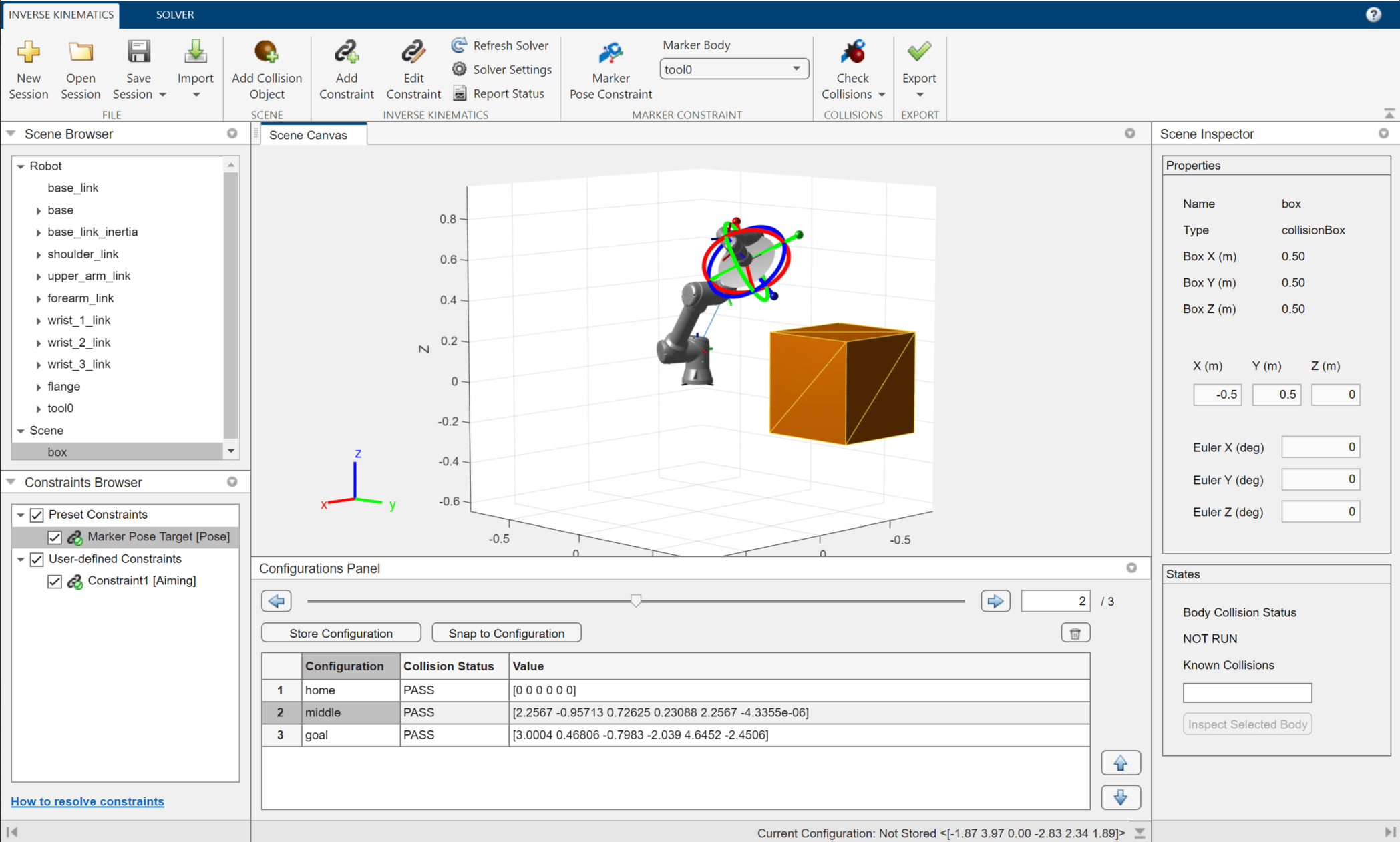
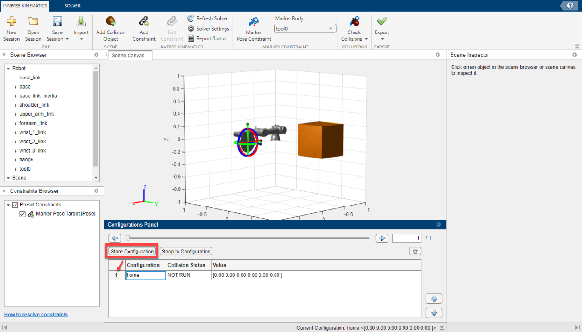
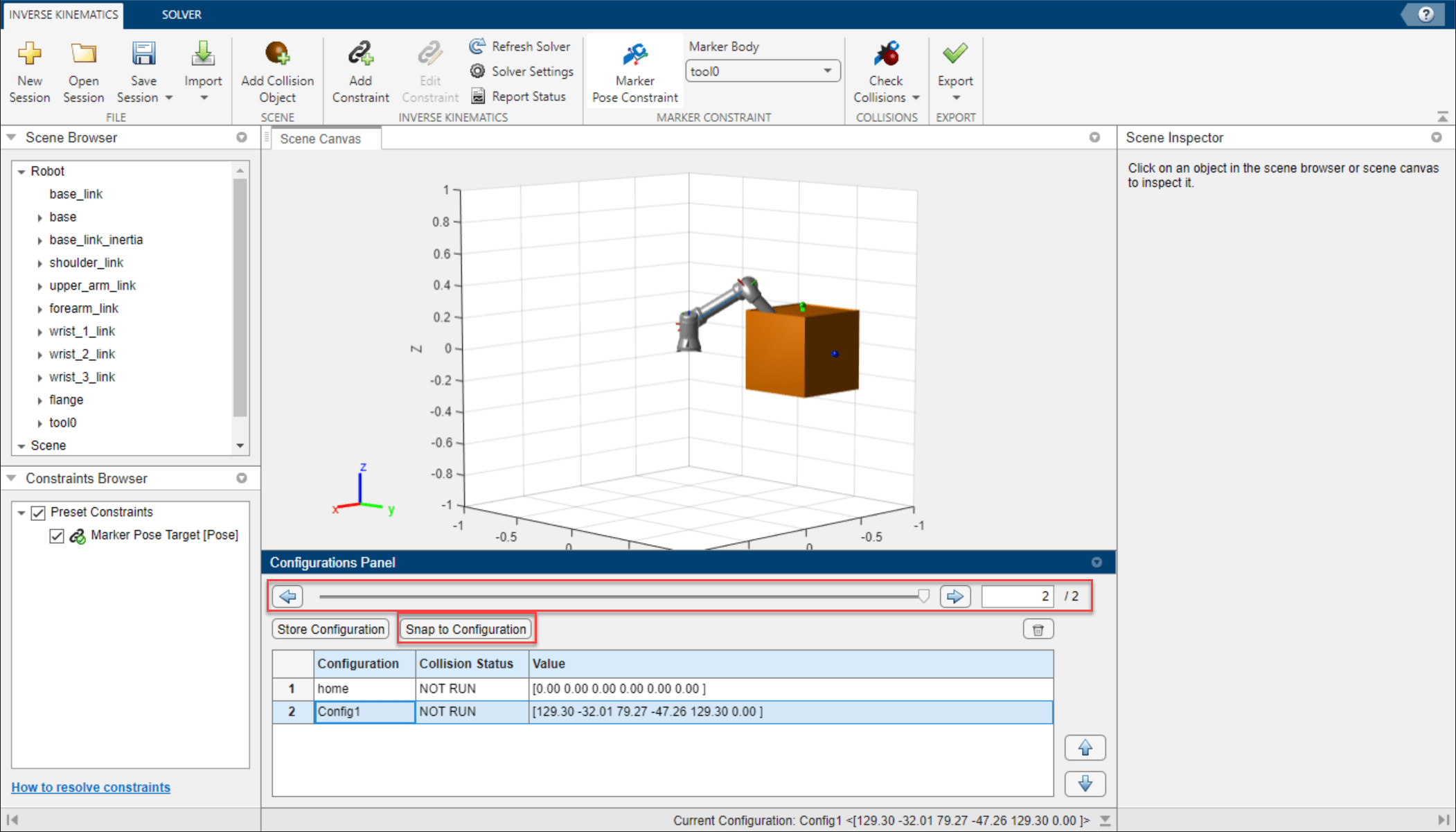
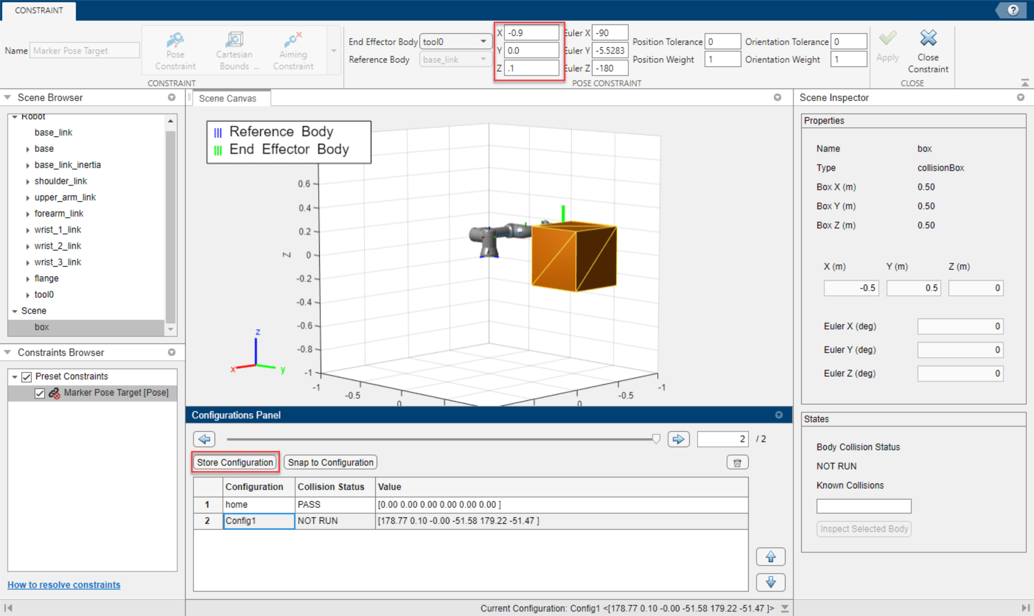
Before moving the robot, click Store Configuration to save the current joint configuration of the robot as shown in the Scene Canvas. This adds the configuration to the table in the Configurations Panel with a default configuration name, the Collision Status, and Value of each joint as a vector. Both the name and value of each configuration can be edited by double-clicking the respective element. Rename this configuration to home and leave its Value at [0.00 0.00 0.00 0.00 0.00 0.00].

Snag_671cc01d.png

Create another configuration, but this time making it collide with the box. Set the end-effector into the center of the box at [-0.5 0.5 0] using the Marker Pose Constraint, and store the configuration. To switch the view between multiple configurations, select a configuration, click Snap to Configuration or click the forward or backward step buttons to step to switch the current configuration.

Check Collisions

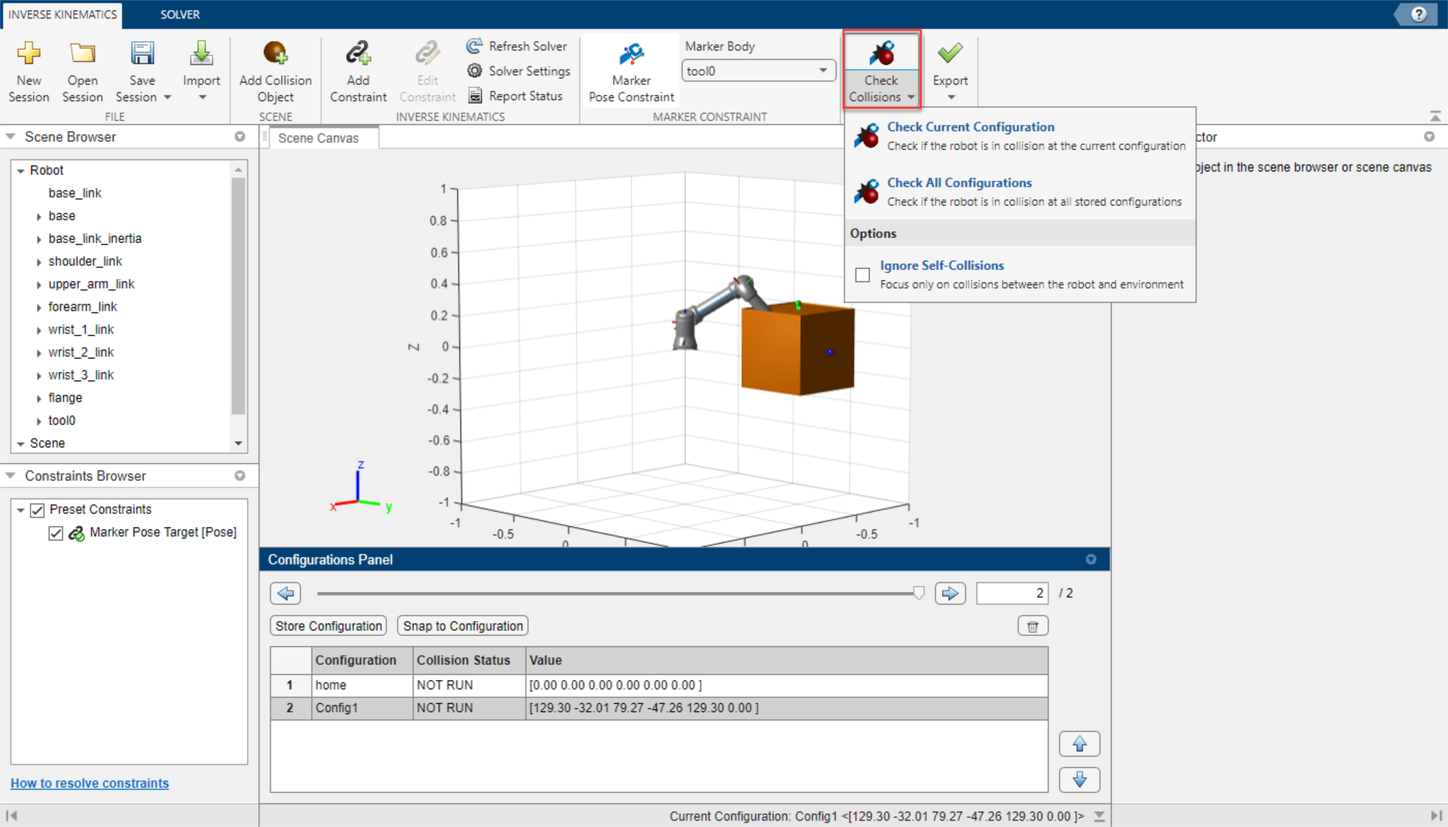
Click Check Collisions > Check All Configurations to update the Collision Status of all the stored configurations. To check one configuration, select desired configuration, click Snap to Configuration, and click Check Collisions > Check Current Configuration to update the Collision Status of the currently selected configuration.

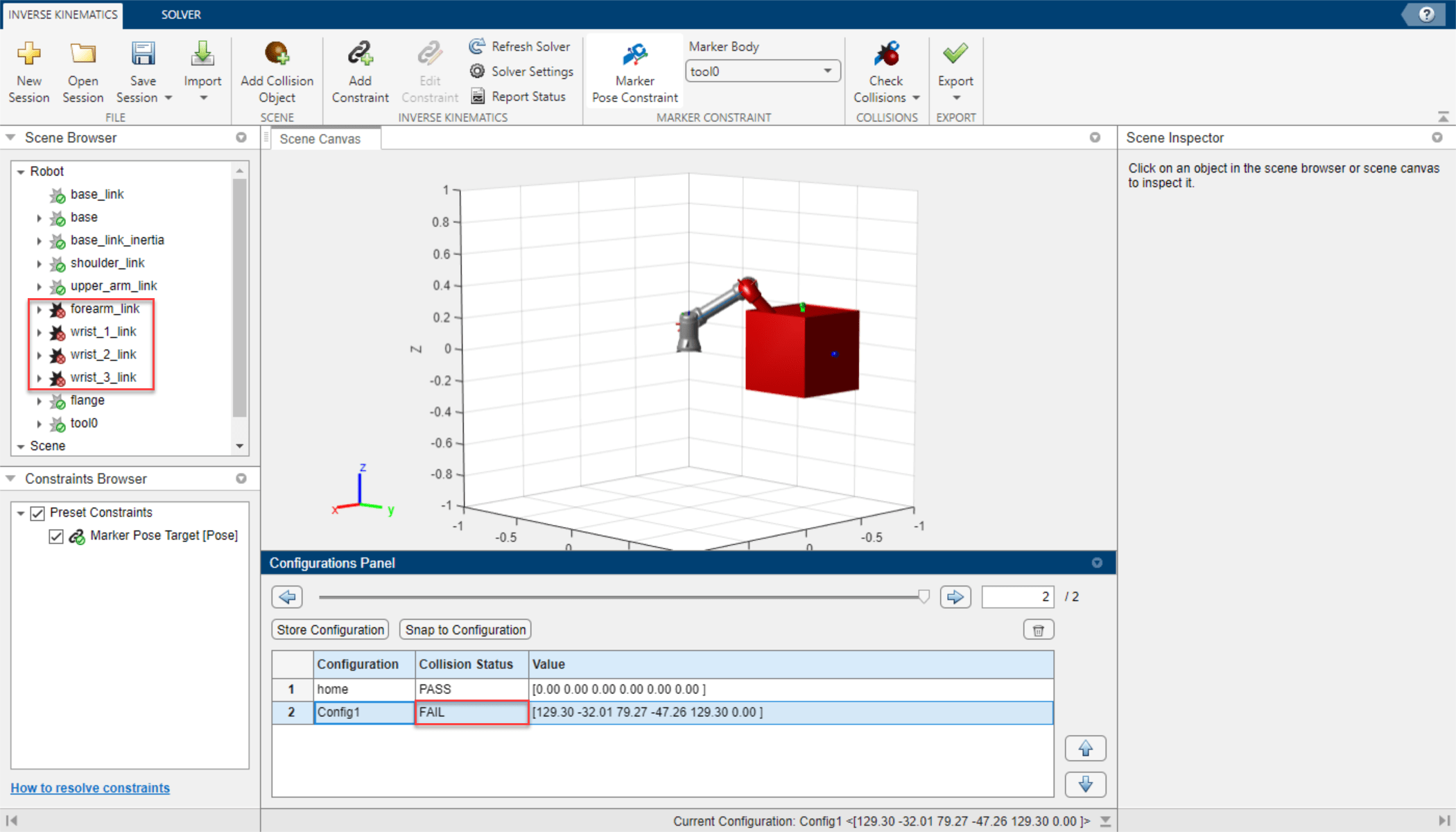
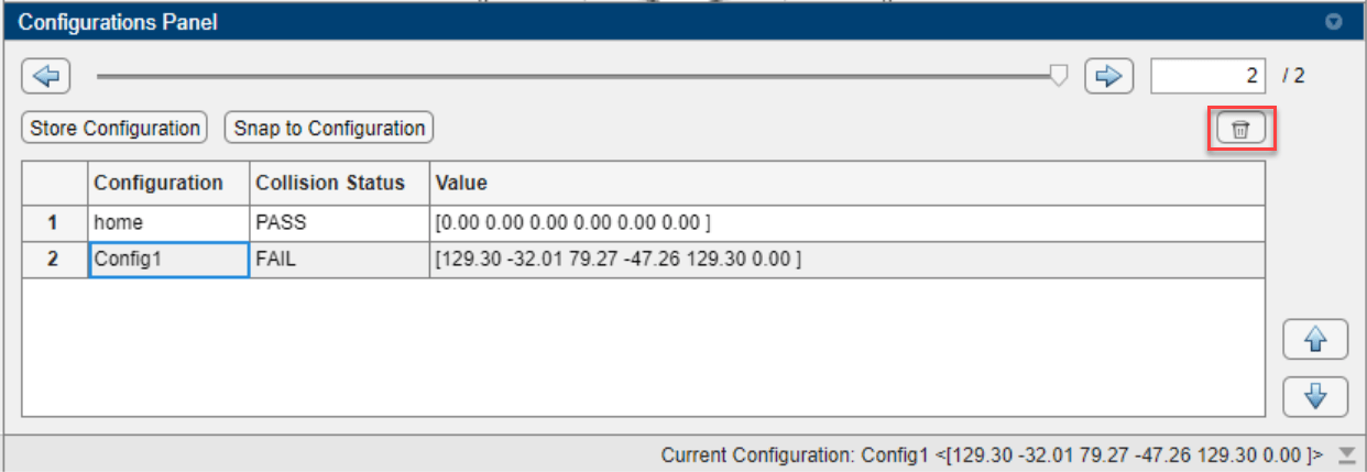
After the collision checking, the Collision Status of the first and second configuration contain PASS and FAIL respectively. Select the configuration that failed the collision check. The bodies in the Scene Browser update for the selected configuration to display an red x or green check icon, indicating that the body is in-collision or collision-free respectively. The bodies marked as in-collision will also be highlighted in red in the Scene Canvas. Note that flange and tool0 are indicated to be collision-free even though they appear to be positionally in-collision. This is because those bodies are just frames and do not contain collision meshes. If you intend to check for collisions, ensure before importing any robot that the physical bodies of your robot contain collision meshes.

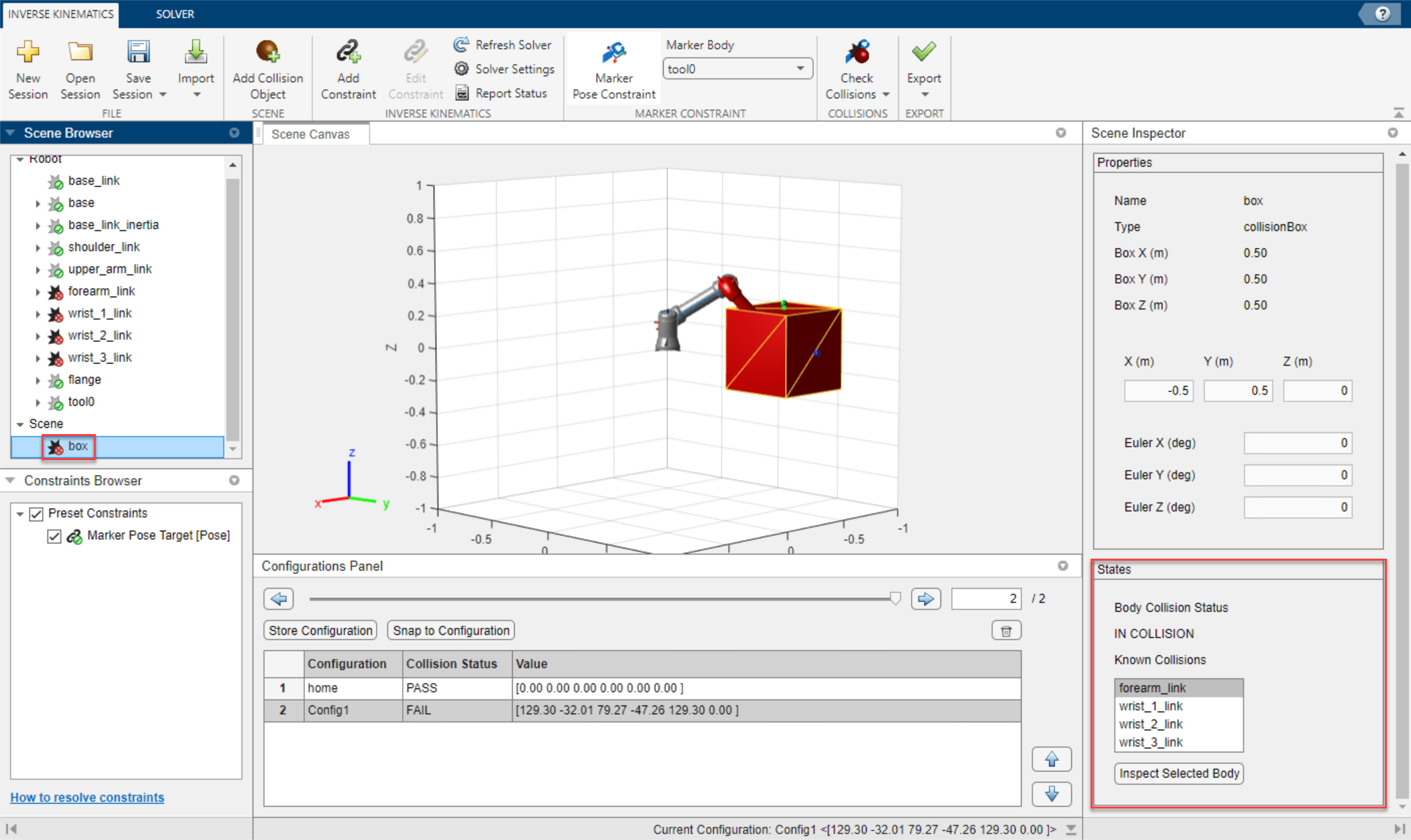
Select the box, either by clicking on it in the Scene Browser, or in the Scene Canvas, and then inspect the States pane. The States pane contains the position, orientation, collision status, and a list of all the known collisions since the last collision check. The Known Collisions list shows all of the bodies colliding with the selected body. Selecting any of the bodies from the list and clicking Inspect Selected Body will switch the Scene Inspector to that body.

Create Configuration Path

To create a path, add configurations to the table sequential sequentially. Since the second configuration is in-collision with the box, select it and click delete.

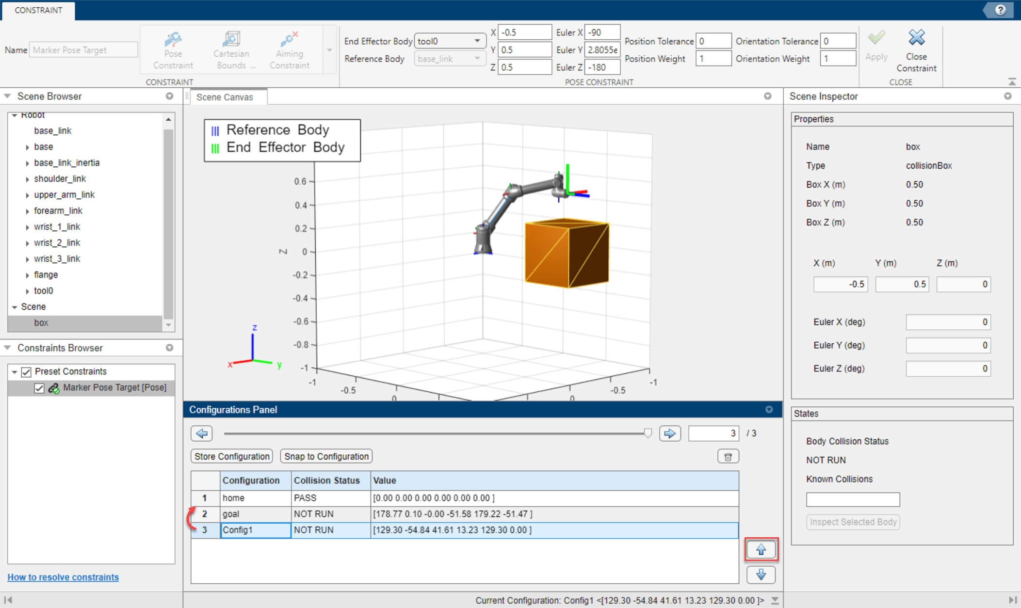
Set the target marker pose to behind the box at [-0.9 0.0 0.1], and store the configuration. This configuration will the be goal configuration so rename it as goal.

Snap to configuration home and add an additional configuration over the box at [-0.5 0.5 0.5] to act as an intermediate configuration between home and goal. If a configuration needs to be modified, snap to that configuration, adjust the target marker pose, save a new configuration, and delete the old configuration. Click the move configuration buttons to move the new configuration between the home and goal configurations.

Click Check Collisions > Check All Configurations to check all the configurations for collisions. If a configuration does not pass, adjust it as necessary.

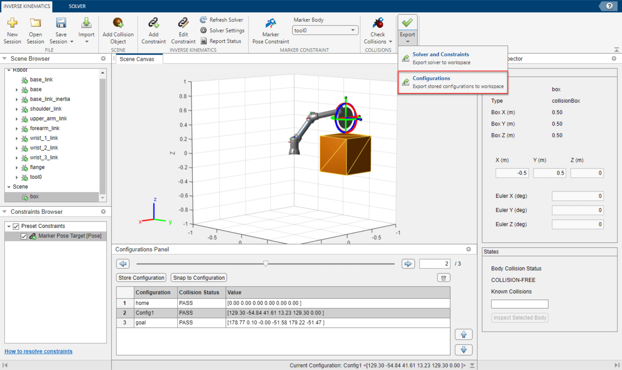
Export Configurations as Waypoints

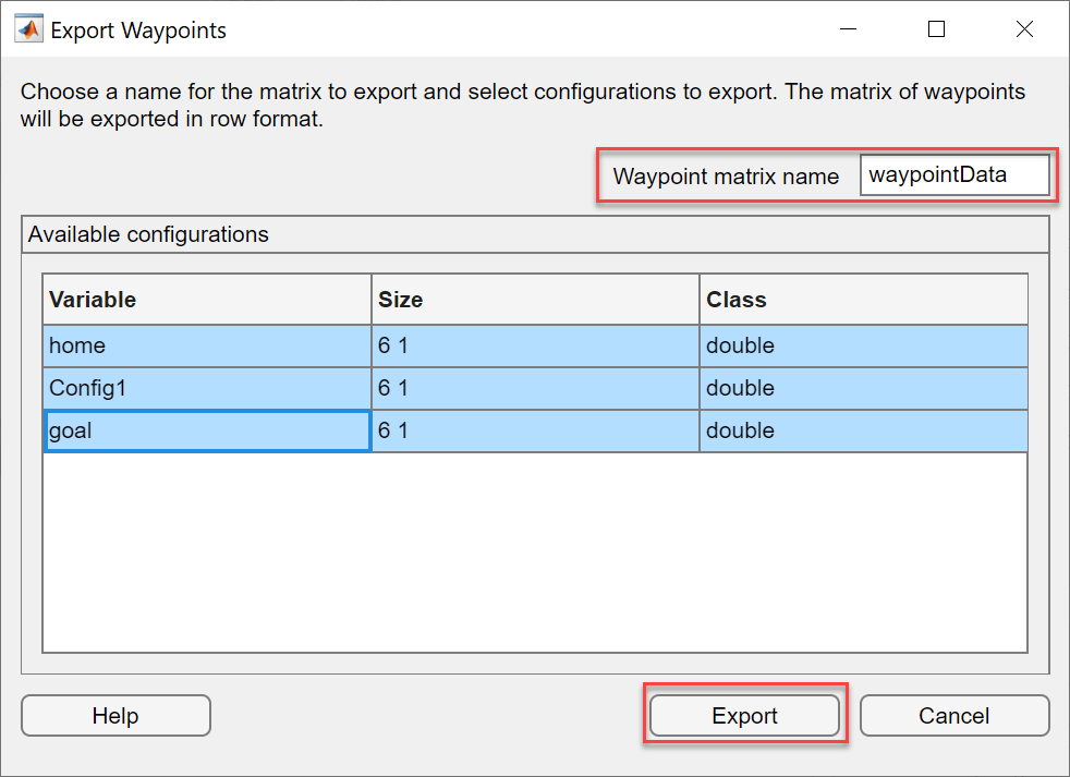
Saving the session will also save the stored configurations within the session, but to export the configurations as waypoints to the MATLAB™ Workspace, click Export > Configurations. Select all of the configurations to export, specify the name of the waypoint matrix in Waypoint matrix name and click Export. Check your workspace for a matrix containing waypoints. Note that the size of the waypoint matrix is dependent on the number of configurations exported and the number of joints of the robot, and will be exported in row format. The dimensions of the waypoint matrix for this example is 3x6.

Related Examples

Parameters

expand all

Session

Use the Inverse Kinematics tab to manage session, add and edit constraints, check collisions for configurations, and import and export solvers, constraints, and configurations. The parameters and buttons in this tab are usable only after a session has been created or loaded.

Parameters/ButtonsDescription
New Session

Click New Session to load a specified robot from the workspace or from the lists of robots in the robot library using the New Session dialog box.

Open Session

Click Open Session to load a saved session MAT-file.

Save Session

Click Save Session to save the current session as a MAT-file.

Import
Add Collision Object

Click Add Collision Object to add collision objects to the scene from the workspace using the Add Collision Object dialog box.

Add Constraint

Click Add Constraint to add a constraint to the inverse kinematics solver using the Constraint tab.

Edit Constraint

Click Edit Constraint to edit the selected solver constraint using the Constraint tab.

Refresh Solver

Click Refresh Solver to run the inverse kinematics solver using the current configuration as the initial guess.

Solver Settings

Click Solver Settings to edit the inverse kinematics solver settings using the Solver tab.

Report Status

Click Report Status to view the status of the most recent inverse kinematics solver solution using the Solution Report dialog box.

Marker Pose Constraint

Click Marker Pose Constraint to edit the Marker Pose Target from the Constraint tab.

Marker Body

Select a body from the list of bodies in the loaded robot model to be constrained by the marker pose target constraint. By default, Marker Body is set to the last body in the robot model.

Check Collisions
  • Click Check Collisions > Check Current Configuration to check the current configuration for collisions with collision objects in the scene.

  • Click Check Collisions > Check All Configurations to check the all stored configurations for any collisions with collision objects in the scene.

  • Select Ignore Self-Collisions to ignore collisions between bodies of the robot.

Export
  • Click Export > Solver and Constraints to export the current solver and constraints to the workspace as objects using the Export Solver and Constraints dialog box.

  • Click Export > Configurations to export configurations from the Configurations Panel to the workspace as a matrix using the Export Waypoints dialog box.

These parameters specify settings for the inverse kinematics solver. To access these parameters, open the Solver tab. To open the Solver tab, on the Inverse Kinematics tab, select Solver Settings.

ParametersDescription
Solver Algorithm

Inverse kinematics solver algorithm, specified as one of these options:

  • BFGS Gradient Projection (default)

  • Levenberg-Marquardt

For more information on how to select a solver, see Choose an Algorithm.

Max IterationsMaximum number of iterations for the inverse kinematics solver to run, specified as a positive integer. The default value is 50.
Max Time

Maximum time that the inverse kinematics solver can search for a solution, specified as a positive scalar in seconds. The default value is 5.

Enforce Joint Limits

Select to set the inverse kinematics solver to enforce joint limits from the robot model. The default value is on.

For more details about enforcing joint limits, see Solver Parameters.

Allow Random Restart

Select to allow the inverse kinematics solver to restart with a different randomly generated initial guess if the algorithm approaches a solution that does not satisfy the constraints. The default value is on.

For more details about enforcing joint limits, see Solver Parameters.

Click Reset Settings > Reset Settings and Reset Settings > Reset To Default Settings to reset the inverse kinematics solver settings to the last stored value and default settings respectively.

After editing the solver settings, click Apply to Solver to apply changes to the current inverse kinematics solver.

To open the Constraint tab and create a constraint, on the Inverse Kinematics tab, select Add Constraint. Set the name of the constraint and select the type of constraint. The Constraint tab also contains a section with parameters for the selected constraint:

After setting the constraint parameters, click Apply to save your changes and select Close Constraint to return to the Inverse Kinematics tab. If you do not click Apply before closing the Constraint tab, Inverse Kinematics Designer does not save your changes..

Start new session and select robot model as a rigidBodyTree either from the Rigid body tree list or the MATLAB workspace. To import a robot into the workspace, use either the loadrobot function or importrobot function.

For more information about how to create a rigid body tree, see Build Basic Rigid Body Tree Models.

For a full list of all the rigid body trees included with the Robotics System Toolbox™, see the robotname input of loadrobot.

Add collision meshes from the MATLAB workspace, specified as collisionBox, collisionCylinder, collisionSphere, or collisionMesh objects. The Add Collision Object dialog box is accessible by clicking Add Collision Object in the Inverse Kinematics tab.

View the details of the most recent inverse kinematics solution in the Solution Report dialog box. To access these parameters, on the Inverse Kinematics tab, select Report Status.

These parameters are read-only.

ParameterDescription
IterationsNumber of iterations needed to achieve the solution result.
Number of Random Restarts

Number of times that the solution randomly restarted. Random restarts are triggered when the algorithm approaches a solution that does not satisfy the constraints. The solver restarts with a randomly generated initial guess.

Constraint Violations

Constraint violations, indicated as a 1-by-N structure array, where N is the number of enabled constraints in the session. Select 1xN struct array to print the details of each constraint violation in the Command Window. See Constraint Violation Format for more details.

Status

Status of the solution, indicated as either Success or Best available.

Success indicates that the solver successfully reached a configuration that satisfies all constraints.

Best available indicates that the solver did not reach a configuration that satisfies all constraints, and is showing the best available configuration it could achieve.

Exit FlagExit flag of the solver. See Exit Flags for more information.
Constraints

Click Pose Constraint in the Constraint tab to open the Pose Constraint tab section to create a constraint.

ParameterDescription
End Effector BodyEnd-effector body, specified as a selection from a list of bodies in the loaded robot model. The default value is set to the last body in the loaded robot model.
Reference BodyReference body, specified as a selection from a list of bodies in the loaded robot model. The default value is set to the first body in the loaded robot model.
XTarget x position of the end effector in the reference frame of the Reference Body, specified as a scalar in meters. The default value is 0.
YTarget y position of the end effector in the reference frame of the Reference Body, specified as a scalar in meters. The default value is 0.
ZTarget z position of the end effector in the reference frame of the Reference Body, specified as a scalar in meters. The default value is 0.
Euler XTarget Euler x rotation of the end-effector body in the reference frame of the Reference Body, specified as a scalar in degrees. The default value is 0.
Euler YTarget Euler y rotation of the end-effector body in the reference frame of the Reference Body, specified as a scalar in degrees. The default value is 0.
Euler ZTarget Euler z rotation of the end-effector body in the reference frame of the Reference Body, specified as a scalar in degrees. The default value is 0.
Position ToleranceTolerance for the end-effector position, specified as a nonnegative scalar in meters. The default value is 0.01.
Position WeightWeight for the end-effector position, specified as a nonnegative scalar. The default value is 1.
Orientation ToleranceTolerance for the end-effector orientation, specified as a nonnegative scalar in degrees. The default value is 1.
Orientation WeightWeight for the end-effector orientation, specified as a nonnegative scalar. The default value is 1.

Click Cartesian Bounds Constraint in the Constraint tab to open the Cartesian Bounds Constraint tab section to create a constraint.

ParameterDescription
End Effector BodyEnd-effector body, specified as a selection from a list of bodies in the loaded robot model. The default value is set to the last body in the loaded robot model.
Reference BodyReference body, specified as a selection from a list of bodies in the loaded robot model. The default value is set to the first body in the loaded robot model.
XTarget x position of the end effector in the reference frame of the Reference Body, specified as a scalar in meters. The default value is 0.
YTarget y position of the end effector in the reference frame of the Reference Body, specified as a scalar in meters. The default value is 0.
ZTarget z position of the end effector in the reference frame of the Reference Body, specified as a scalar in meters. The default value is 0.
Euler XTarget Euler x rotation of the end-effector body in the reference frame of the Reference Body, specified as a scalar in degrees. The default value is 0.
Euler YTarget Euler y rotation of the end-effector body in the reference frame of the Reference Body, specified as a scalar in degrees. The default value is 0.
Euler ZTarget Euler z rotation of the end-effector body in the reference frame of the Reference Body, specified as a scalar in degrees. The default value is 0.
X MinMinimum x bound on end-effector position relative to the reference frame of the Reference Body, specified as a scalar in meters. The default value is -0.5.
Y MinMinimum y bound on end-effector position relative to the reference frame of the Reference Body, specified as a scalar in meters. The default value is -0.5
Z MinMinimum z bound on end-effector position relative to the reference frame of the Reference Body, specified as a scalar in meters. The default value is -0.5
X MaxMaximum x bound on end-effector position relative to the reference frame of the Reference Body, specified as a scalar in meters. The default value is 0.5
Y MaxMaximum y bound on end-effector position relative to the reference frame of the Reference Body, specified as a scalar in meters. The default value is 0.5
Z MaxMaximum z bound on end-effector position relative to the reference frame of the Reference Body, specified as a scalar in meters. The default value is 0.5
X WeightWeight of the constraint on x bound, specified as a scalar. The default value is 1.
Y WeightWeight of the constraint on y bound, specified as a scalar. The default value is 1.
Z WeightWeight of the constraint on z bound, specified as a scalar. The default value is 1.

Click Aiming Constraint in the Constraint tab to open the Aiming Constraint tab section to create a constraint.

ParameterDescription
End Effector BodyEnd-effector body, specified as a selection from a list of bodies in the loaded robot model. The default value is set to the last body in the loaded robot model.
Reference BodyReference body, specified as a selection from a list of bodies in the loaded robot model. The default value is set to the first body in the loaded robot model.
X TargetTarget x position relative to Reference Body, specified as a scalar in meters. The default value is 0.
Y TargetTarget y position relative to Reference Body, specified as a scalar in meters. The default value is 0.
Z TargetTarget z position relative to Reference Body, specified as a scalar in meters. The default value is 0.
Angular ToleranceMaximum allowed angular tolerance, specified as a nonnegative scalar in degrees. The default value is 1.
Constraint WeightWeight of constraint, specified as a scalar. The default value is 1.

Click Joint Bounds Constraint in the Constraint tab to open the Joint Bounds Constraint tab section to create a constraint.

ParameterDescription
Upper Joint LimitsUpper joint limit angles, specified as a N-element row vector of angles in degrees, where N is the number of moving joints in the robot model. The default value is 180*ones(1,N).
Lower Joint LimitsLower joint limit angles, specified as a N-element row vector of angles in degrees, where N is the number of moving joints in the robot model. The default value is -180*ones(1,N).
Joint Limit WeightsJoint limit weights, specified as a N-element row vector where N is the number of moving joints in the robot model. The default value is ones(1,N).

On the Constraint tab, select Distance Bounds Constraint in the Constraint tab to create a distance bounds constraint and open the Distance Bounds Constraint section.

ParameterDescription
End Effector BodyEnd-effector body, selected from a list of bodies in the loaded robot model. The default value is the last body in the loaded robot model.
Reference BodyReference body, selected from a list of bodies in the loaded robot model. The default value is the first body in the loaded robot model.
Max DistanceMaximum distance bound on the end-effector position relative to the reference frame of the Reference Body, specified as a scalar in meters. The default value is 0.
Min DistanceMinimum distance bound on end-effector position relative to the reference frame of the Reference Body, specified as a scalar in meters. The default value is 0.
Distance WeightWeight for the end-effector position, specified as a nonnegative scalar. The default value is 1.

On the Constraint tab, select Fixed Joint Constraint in the Constraint tab to create a fixed joint constraint and open the Fixed Joint Constraint section.

ParameterDescription
Successor BodySuccessor body, selected from a list of bodies in the loaded robot model. The default value is the last body in the loaded robot model
Predecessor BodyPredecessor body, selected from a list of bodies in the loaded robot model. The default value is the first body in the loaded robot model.
Position ToleranceTolerance for the end-effector position, specified as a nonnegative scalar in meters. The default value is 0.01.
Position WeightWeight for the end-effector position, specified as a nonnegative scalar. The default value is 1.
Orientation ToleranceTolerance for the end-effector orientation, specified as a nonnegative scalar in degrees. The default value is 1.
Orientation WeightWeight for the end-effector orientation, specified as a nonnegative scalar. The default value is 1.

To set the successor and predecessor transforms, select Successor Transform or Predecessor Transform, respectively:

ParameterDescription
XTarget x-position of the successor or predecessor transform in the reference frame of the corresponding body. specified as a scalar in meters. The default value is 0.
YTarget y-position of the successor or predecessor transform in the reference frame of the corresponding body, specified as a scalar in meters. The default value is 0.
ZTarget z-position of the successor or predecessor transform in the reference frame of the corresponding body, specified as a scalar in meters. The default value is 0.
Euler XTarget Euler x-rotation of the successor or predecessor transform in the reference frame of the corresponding body, specified as a scalar in degrees. The default value is 0.
Euler YTarget Euler y-rotation of the successor or predecessor transform in the reference frame of the corresponding body, specified as a scalar in degrees. The default value is 0.
Euler ZTarget Euler z-rotation of the successor or predecessor transform in the reference frame of the corresponding body, specified as a scalar in degrees. The default value is 0.
Import from workspaceImport a transform from the workspace as an se3 transformation object.

On the Constraint tab, select Prismatic Joint Constraint in the Constraint tab to create a prismatic joint constraint and open the Prismatic Joint Constraint tab.

ParameterDescription
Successor BodySuccessor body, selected from a list of bodies in the loaded robot model. The default value is the last body in the loaded robot model
Predecessor BodyPredecessor body, selected from a list of bodies in the loaded robot model. The default value is the first body in the loaded robot model.
Position ToleranceTolerance for the position of the aligned successor and predecessor transforms, specified as a nonnegative scalar in meters. The default value is 0.01.
Position WeightWeight for the position of the aligned successor and predecessor transforms, specified as a nonnegative scalar. The default value is 1.
Orientation ToleranceTolerance for the orientation of the aligned successor and predecessor transforms, specified as a nonnegative scalar in degrees. The default value is 1.
Orientation WeightWeight for the orientation of the aligned successor and predecessor transforms, specified as a nonnegative scalar. The default value is 1.
Joint LimitsPosition limits of the joint constraint, specified as a two-element row vector of the form [minimum maximum], in meters. The default value is [-1 1].
Joint Limits WeightWeight for the joint position limits, specified as a nonnegative scalar. The default value is 1.

To set the successor and predecessor transforms, select Successor Transform or Predecessor Transform, respectively:

ParameterDescription
XTarget x-position of the successor or predecessor transform in the reference frame of the corresponding body. specified as a scalar in meters. The default value is 0.
YTarget y-position of the successor or predecessor transform in the reference frame of the corresponding body, specified as a scalar in meters. The default value is 0.
ZTarget z-position of the successor or predecessor transform in the reference frame of the corresponding body, specified as a scalar in meters. The default value is 0.
Euler XTarget Euler x-rotation of the successor or predecessor transform in the reference frame of the corresponding body, specified as a scalar in degrees. The default value is 0.
Euler YTarget Euler y-rotation of the successor or predecessor transform in the reference frame of the corresponding body, specified as a scalar in degrees. The default value is 0.
Euler ZTarget Euler z-rotation of the successor or predecessor transform in the reference frame of the corresponding body, specified as a scalar in degrees. The default value is 0.
Import from workspaceImport a transform from the workspace as an se3 transformation object.

On the Constraint tab, select Revolute Joint Constraint in the Constraint tab to create a revolute joint constraint and open the Revolute Joint Constraint tab.

ParameterDescription
Successor BodySuccessor body, selected from a list of bodies in the loaded robot model. The default value is the last body in the loaded robot model
Predecessor BodyPredecessor body, selected from a list of bodies in the loaded robot model. The default value is the first body in the loaded robot model.
Position ToleranceTolerance for the position of the aligned successor and predecessor transforms, specified as a nonnegative scalar in meters. The default value is 0.01.
Position WeightWeight for the position of the aligned successor and predecessor transforms, specified as a nonnegative scalar. The default value is 1.
Orientation ToleranceTolerance for the orientation of the aligned successor and predecessor transforms, specified as a nonnegative scalar in degrees. The default value is 1.
Orientation WeightWeight for the orientation of the aligned successor and predecessor transforms, specified as a nonnegative scalar. The default value is 1.
Joint LimitsPosition limits of the joint constraint, specified as a two-element row vector of the form [minimum maximum], in degrees. The default value is [-180 180].
Joint Limits WeightWeight for the joint position limits, specified as a nonnegative scalar. The default value is 1.

To set the successor and predecessor transforms, select Successor Transform or Predecessor Transform, respectively:

ParameterDescription
XTarget x-position of the successor or predecessor transform in the reference frame of the corresponding body. specified as a scalar in meters. The default value is 0.
YTarget y-position of the successor or predecessor transform in the reference frame of the corresponding body, specified as a scalar in meters. The default value is 0.
ZTarget z-position of the successor or predecessor transform in the reference frame of the corresponding body, specified as a scalar in meters. The default value is 0.
Euler XTarget Euler x-rotation of the successor or predecessor transform in the reference frame of the corresponding body, specified as a scalar in degrees. The default value is 0.
Euler YTarget Euler y-rotation of the successor or predecessor transform in the reference frame of the corresponding body, specified as a scalar in degrees. The default value is 0.
Euler ZTarget Euler z-rotation of the successor or predecessor transform in the reference frame of the corresponding body, specified as a scalar in degrees. The default value is 0.
Import from workspaceImport a transform from the workspace as an se3 transformation object.
Import

Import an inverse kinematics solver from the MATLAB workspace, specified as either a generalizedInverseKinematics, or inverseKinematics object. Solvers in the Workspace appear in the Available solvers table. Select a solver and click Import to import the solver into the Inverse Kinematics Designer app. If a solver from the Workspace does not appear in the Available solvers table, click Refresh.

Import joint configurations from the MATLAB workspace, specified as an M-by-N matrix of doubles where M is the number of configurations, and N is the number of moveable joints in the robot. Configuration data in the Workspace appear in the Configurations in the workspace table. Select configuration data and click Import to import the configuration data into the Inverse Kinematics Designer app.

If a configuration in the Workspace does not appear in the Configurations in the workspace table, click Refresh.

Import inverse kinematics constraints from the Workspace, specified as a constraintAiming, constraintPoseTarget, constraintCartesianBounds, or constraintJointBounds object. Constraint objects in the Workspace appear in the Configurations in the workspace table. Select the desired constraint objects and click Import to import the constraints into the Inverse Kinematics Designer app.

If a configuration in the Workspace does not appear in the Constraint objects in the workspace table, click Refresh.

Import a transform from the workspace to use as a successor or predecessor transform, specified as an se3 object. Transforms in the workspace appear in the SE(3) objects in the workspace table. Select the desired transform and click Import to import the transform into the Inverse Kinematics Designer app.

If a transform in the workspace does not appear in the SE(3) objects in the workspace table, click Refresh.

Export

Change solver and constraint export settings, and export the solver and constraints to the MATLAB. To access these parameters, on the Inverse Kinematics tab, select Export > Solver and Constraints. When all settings and selections are complete, click Export to export the solver and constraints to the workspace.

ParameterDescription
Export solverSelect to include the inverse kinematics solver when exporting. The default value is on.
Solver nameName of the inverse kinematics solver. The default value is ikSolver.
Export constraintsSelect to include the solver constraints when exporting. The default value is on.
Constraints cell array name

Name of the solver constraints cell array, specified as a string. The default value is ikConstraints.

To enable this parameter, select the Export constraints parameter.

Available constraints

Table containing solver constraints, listing the name, size, and class of each constraint. Select constraints from this table and click Export to export the constraints to the workspace.

To enable this parameter, select the Export constraints parameter.

Export configurations as waypoints using the Export Waypoints dialog box. To access these parameters, on the Inverse Kinematics tab, select Export > Configurations. When selections are complete, click Export to export the waypoints as an M-by-N matrix of data type double to the MATLAB workspace, where M is the number of waypoints, and N is the number of movable joints in the robot.

ParameterDescription
Waypoint matrix nameName of waypoint matrix. The default value is waypointData.
Available configurations

Table containing available configurations, listing the name, size, and class of each constraint. Select configurations from this table and click Export to export the configurations to the workspace as waypoints.

Programmatic Use

expand all

inverseKinematicsDesigner opens the Inverse Kinematics Designer app.

inverseKinematicsDesigner(sessionFileName) opens the Inverse Kinematics Designer app and loads the specified inverse kinematics session MAT file that was previously saved from the app.

More About

expand all

Version History

Introduced in R2022a

expand all