このページは機械翻訳を使用して翻訳されました。最新版の英語を参照するには、ここをクリックします。
ガイド付きハードウェアセットアップ
HDL Verifier™ Support Package for Intel® FPGA Boards、HDL Verifier Support Package for Microchip FPGA Boards、または HDL Verifier Support Package for Xilinx® FPGA Boards の機能を使用する前に、ホスト コンピュータとハードウェア ボード間の通信を確立する必要があります。インストーラーがサポート パッケージのインストールを完了すると、ハードウェア ボードとの通信を確立するプロセスをガイドします。
サポート パッケージがすでにインストールされている場合は、アドオン マネージャーを開いてハードウェアのセットアップを開始できます。

アドオン マネージャーで、Gear アイコン ![]() をクリックしてハードウェア セットアップ プロセスを開始します。
をクリックしてハードウェア セットアップ プロセスを開始します。
FPGA検証で使用するボードとインターフェースの選択
リストから、このボードで使用するハードウェア ボードとインターフェイスを選択します。サポートされているボードとインターフェイスの完全なリストについては、FPGA検証でサポートされているFPGAデバイス を参照してください。HDL Verifier は、Windows® オペレーティング システムでのみ FPGA インザループ (FIL) の PCI Express® 接続をサポートします。
セットアップ プロセスには、この手順で選択したインターフェイスに応じて次の手順が含まれます。
イーサネット
セットアップ プロセスを完了するために必要なハードウェアがあることを確認します。接続要件を参照してください。
セットアップ手順に従って、イーサネット インターフェイスを使用してハードウェア ボードをセットアップします。接続設定を参照してください。
ホスト コンピューターのネットワーク インターフェイス カードを構成します。ホストコンピュータ上のNICを構成するを参照してください。
ホスト コンピューターとハードウェア ボード間の接続を確認します。セットアップの確認を参照してください。
Versal、Zynq、または Intel Agilex 7 SoC ボード上のイーサネット
セットアップ プロセスを完了するために必要なハードウェアがあることを確認します。接続要件を参照してください。
ホスト コンピューターのネットワーク インターフェイス カードを構成します。ホストコンピュータ上のNICを構成するを参照してください。
ハードウェア ボードと互換性のあるセキュア デジタル (SD) カード イメージ ファイルを SD カード ドライブ パスにコピーします。ドライブを選択してファームウェアをロードするを参照してください。
ハードウェア ボードを SD カードから起動するように設定します。ジャンパーを設定するを参照してください。
ハードウェア ボードをホスト コンピューターに接続します。Versal® または Zynq® SoC ボードについては、ハードウェアを接続する を参照してください。Intel Agilex® 7 SoC ボードについては、Intel Agilex 7 を接続 を参照してください。
ホスト コンピューターとハードウェア ボード間の接続を確認します。セットアップの確認を参照してください。
JTAG
PCI Express
セットアップ プロセスを完了するために必要なハードウェアがあることを確認します。接続要件を参照してください。
ホスト コンピューターに PCIe ドライバーをインストールします。PCI Express ドライバーをインストールするを参照してください。
ハードウェア ボード上のジャンパーを構成します。ジャンパーを設定するを参照してください。
セットアップ手順に従って、PCI Express インターフェイスを使用してハードウェア ボードをセットアップします。接続設定を参照してください。
USBイーサネット
セットアップ プロセスを完了するために必要なハードウェアがあることを確認します。接続要件を参照してください。
Windows のみ — ホスト コンピューターに USB イーサネット ドライバーをインストールします。USBイーサネットドライバーをインストールするを参照してください。
ハードウェア ボードと互換性のある SD カード イメージ ファイルを SD カード ドライブ パスにコピーします。ドライブを選択してファームウェアをロードするを参照してください。
ハードウェア ボード上のジャンパーを構成します。ジャンパーを設定するを参照してください。
ハードウェア ボードをホスト コンピューターに接続します。ハードウェアを接続するを参照してください。
ホスト コンピューターで USB イーサネットまたは RNDIS ガジェットを構成します。ホストコンピュータでUSBを構成するを参照してください。
ホスト コンピューターとハードウェア ボード間の接続を確認します。セットアップの確認を参照してください。
接続要件
ガイド付きセットアップ ウィザードには、ハードウェア要件のチェックリストが表示されます。セットアップ プロセスを完了するために必要なハードウェアがあることを確認します。
メモ
後の手順でプロンプトが表示されるまで、ボードに接続したり、電源を入れたりしないでください。
イーサネット要件
FPGAまたはSoC開発ボード
USB-JTAG ケーブル (FPGA ボードのみ)
Vivado®、Quartus®、または Microchip Libero® SoC ソフトウェアがインストールされており、サポートされているバージョンが FPGA検証要件 にリストされている (FPGA ボードのみ)
専用ギガビット ネットワーク インターフェイス カード (NIC) または USB 3.0 ギガビット イーサネット アダプタ ドングル
イーサネットケーブル
ボードに必要な場合は電源アダプタ
Intel Agilex 7 SoC ボードのイーサネット要件
Intel Agilex 7 SoCボード
Quartus Prime Pro ソフトウェアをインストールしました。サポートされているバージョンは FPGA検証要件 に記載されています。
専用ギガビット NIC または USB 3.0 ギガビット イーサネット アダプタ ドングル
イーサネットケーブル
ボードに必要な場合は電源アダプタ
SD カードリーダーと 4 GB 以上の容量の書き込み可能な SD カード
Versal または Zynq SoC ボードのイーサネット要件
Versal または Zynq SoC ボード
専用ギガビット NIC または USB 3.0 ギガビット イーサネット アダプタ ドングル
イーサネットケーブル
ボードに必要な場合は電源アダプタ
SD カードリーダーと 4 GB 以上の容量の書き込み可能な SD カード
JTAG要件
FPGAまたはSoC開発ボード
USB-JTAGケーブル
Vivado または Quartus ソフトウェアがインストールされており、サポートされているバージョンが FPGA検証要件 にリストされている
Digilent® Adept 2 Runtime をインストールしました (Xilinx ボード上の Linux® オペレーティング システムのみ)
ボードに必要な場合は電源アダプタ
PCI Express 要件
HDL Verifier は、Windows オペレーティング システムのみで PCI Express 接続をサポートします。
FPGA開発ボード
USB-JTAGケーブル
Vivado または Quartus ソフトウェアがインストールされており、サポートされているバージョンが FPGA検証要件 にリストされている
PCI Express スロットとマザーボード上の空き容量
ボードに必要な場合は電源アダプタ
USBイーサネットの要件
SoC開発ボード
選択したハードウェアボードがサポートするUSBケーブルの種類に応じて、USB 3.0またはUSB 2.0ケーブルを選択します。
メモ
USB 3.0 をサポートするボードに USB 2.0 ケーブルを使用すると、ケーブルのデータ スループットが低下します。
電源アダプタ(ボードに必要な場合)
SD カードリーダーと 4 GB 以上の容量の書き込み可能な SD カード
接続設定
この手順は、Versal、Zynq、および Intel Agilex 7 SoC ボード以外の FPGA または SoC ボードで JTAG または PCI Express インターフェイス、あるいはイーサネット インターフェイスを選択する場合にのみ必要です。
ガイド付きセットアップ ウィザードには、選択したインターフェイスのセットアップ手順が表示されます。選択したインターフェースを使用してハードウェア ボードを設定するには、次の手順に従います。
イーサネット
ボードの電源スイッチがオフになっていることを確認します。
AC 電源コードを電源プラグに接続し、電源アダプタ ケーブルをハードウェア ボードに差し込みます。
クロスオーバー イーサネット ケーブルを使用して、ハードウェア ボード上のイーサネット コネクタをホスト コンピューター上のイーサネット アダプターに直接接続します。
JTAG ダウンロード ケーブルを使用して、ハードウェア ボードをホスト コンピューターに接続します。
ハードウェア ボード上のすべてのジャンパーが工場出荷時のデフォルト位置にあることを確認します。
ハードウェアボードの電源スイッチをオンにします。
JTAG
ボードの電源スイッチがオフになっていることを確認します。
AC 電源コードを電源プラグに接続し、電源アダプタ ケーブルをハードウェア ボードに差し込みます。
JTAG ダウンロード ケーブルを使用して、ハードウェア ボードをホスト コンピューターに接続します。
ハードウェア ボード上のすべてのジャンパーが工場出荷時のデフォルト位置にあることを確認します。
ハードウェアボードの電源スイッチをオンにします。
PCI Express
ボードの電源スイッチがオフになっていることを確認します。
ボードがサポートする PCI Express レーンの最大数を選択します。詳細については、ボードのユーザーマニュアルを参照してください。
対応ボード PCI Express セットアップ ドキュメンテーション DSP 開発キット、Stratix® V エディション ディップスイッチSW6の3つのスイッチ(PCIE_PRSNT2nx1、x4、x8)をONに設定します。この設定では、8 レーン PCIe (デフォルトのボード設定) を選択します。 https://www.intel.com/content/www/us/en/products/details/fpga/development-kits/stratix/v-gs.html Cyclone® V GT FPGA 開発キット ディップスイッチSW3の2つのスイッチ(PCIe_x1、x4)をONに設定します。この設定では、4 レーン PCIe (デフォルトのボード設定) を選択します。 https://www.intel.com/content/www/us/en/products/details/fpga/development-kits/cyclone/v-gt.html Kintex®-7 KC705 ジャンパー J32 をピン 5 と 6 を接続するように設定します。この設定では、8 レーン PCIe (デフォルトのボード設定) を選択します。 https://www.xilinx.com/products/boards-and-kits/ek-k7-kc705-g.html Virtex®-7 VC707 ジャンパー J49 をピン 5 と 6 を接続するように設定します。この設定では、8 レーン PCIe (デフォルトのボード設定ではありません) を選択します。 https://www.xilinx.com/products/boards-and-kits/ek-v7-vc707-g.html ホストコンピュータの電源をオフにします。
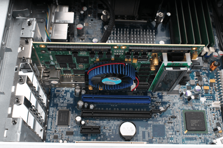
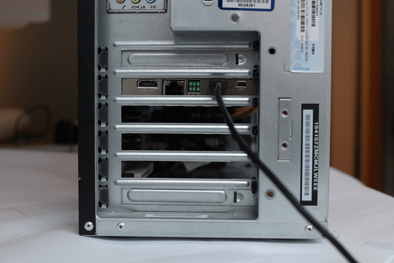
ハードウェア ボードをホスト コンピューター内の PCI Express スロットにインストールします。
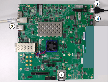
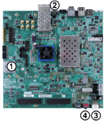
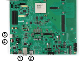
この図は、ホスト コンピュータにインストールされている Stratix V ボードを示しています。このインストールは、サポートされているすべての Intel VC ボードに適用されます。
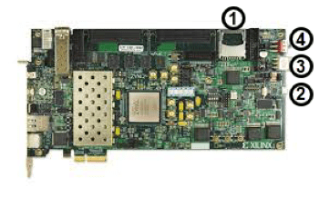
この図は、ホスト コンピュータにインストールされた VC707 ボードを示しています。電源ケーブルは右側にあります。このインストールは、サポートされているすべての Xilinx ボードに適用されます。

Xilinx ボードの場合は、外部電源を壁のコンセントに差し込みます。次に、電源アダプタ ケーブルをハードウェア ボードに差し込みます。
Intel ボードは外部電源を使用しません。
JTAG ケーブルをハードウェア ボードとホスト コンピューターに接続します。PCI Express 接続を使用する場合でも、FPGA をプログラムするには JTAG ケーブルが必要です。
ハードウェアボードの電源スイッチをオンにします。
ホストコンピュータを起動します。
USBイーサネットドライバーをインストールする
この手順は、Windows オペレーティング システムで USB イーサネット インターフェイスを選択する場合にのみ必要です。
USB イーサネット ドライバーがすでにインストールされている場合は、この手順をスキップしてください。
USB イーサネット接続で AXI マネージャーまたは FIL を使用する前に、USB イーサネット ドライバーをインストールする必要があります。ドライバーをインストールするには、Install Driver をクリックします。インストール プロセスにはシステム管理者権限が必要になる場合があります。
ホストコンピュータ上のNICを構成する
この手順は、イーサネット インターフェイスを選択した場合にのみ必要です。
この手順では、ホスト コンピューターがハードウェア ボードと通信できるように構成します。ハードウェア ボード専用のギガビット イーサネット NIC と、カードをハードウェア ボードに接続するイーサネット ケーブルが必要です。同時にインターネットにアクセスしたいがワイヤレス接続がない場合は、ホスト コンピューターに 2 番目のイーサネット NIC が必要です。この場合は、USB 3.0 ギガビット イーサネット アダプタ ドングルの使用を検討してください。
ガイド付きセットアップは、Windows オペレーティング システム上の NIC 構成のみをサポートします。Linux オペレーティング システムの場合は、Linux を設定する の手順に従って NIC を手動で構成します。
ガイド付きセットアップで、ハードウェア ボードに接続する NIC を選択します。NIC がすでに設定されている場合は、Skip this step if your network card is already configured for communicating with the FPGA or SoC board を選択します。
リストには、ホスト コンピューターで検出された接続された NIC が表示されます。メニュー オプションでは、各 NIC が (In Use) または (Available) として表示されます。NIC がデバイスに接続され、IP アドレスが割り当てられている場合、インストーラーは NIC を (In Use) としてマークします。
NIC がリストに表示されない場合は、Refresh をクリックして NIC 検出をトリガーし、リストを更新します。リストを更新すると、たとえば、このペインを表示しているときに USB イーサネット アダプタ ドングルを接続する場合に便利です。
リストされているすべての NIC が使用中の場合は、ハードウェアで使用するために NIC を解放し、Refresh をクリックします。
NIC リストが空の場合、VMWare ソフトウェアが存在すると、NIC 検出が妨げられる可能性があります。ホスト コンピュータ上の NIC の正確なリストを取得するには、VMWare ソフトウェアを削除します。
コントロール パネルで、不足している NIC が無効になっているかどうかを確認します。NIC が無効になっている場合は有効にします。
NIC の IP アドレスはデフォルトのままにします。または、ドット区切りの 4 つの形式で IP アドレスを指定します (例: 192.168.0.1)。
Next をクリックすると、ソフトウェアが NIC を構成します。
ドライブを選択してファームウェアをロードする
この手順は、USB イーサネット インターフェイスまたは Versal、Zynq、または Intel Agilex 7 SoC ボード上のイーサネット インターフェイスを選択する場合にのみ必要です。
USB イーサネットのみ - ホスト コンピュータがハードウェア ボードと通信できるように USB イーサネット インターフェイスを構成します。ホスト コンピューターをハードウェア ボードに接続する USB ケーブルが必要です。
ガイド付きセットアップでは、USB デバイスの IP アドレスをドット区切りの 4 つの形式で指定します (例:
192.168.1.2)。USB ホストの IP アドレスはデフォルトのままにします。Next をクリックすると、後続の手順では USB ホスト IP アドレスを使用して、ホスト コンピューターで検出された USB イーサネット インターフェイスを構成します。次に、インストーラーは FPGA イメージを SD カードに書き込む必要があります。この FPGA イメージはサポート パッケージに含まれています。イメージには、ハードウェア ボードを I/O 周辺機器として使用するために必要な組み込みソフトウェアと FPGA プログラミング ファイルが含まれています。
4 GB 以上の SD カードをホスト コンピューターのカード リーダーに挿入します。カードは FAT32 形式である必要があります。リストから適切なドライブを選択します。FPGA イメージをすでにダウンロードしている場合は、この手順をスキップしてください。

メモ
ファームウェア イメージをカードにダウンロードする前に、SD カードのロックを解除します。カードがボードカードリーダー内にある間は、カードをロック解除したままにしてください。
FPGAイメージをSDカードに書き込みます。ガイド付きセットアップで、カードが入っている SD ドライブの場所を選択し、Next をクリックします。次の画面で、ホスト コンピューターから SD カードにプログラミング ファイルをコピーするには、Write をクリックします。このプロセスにより、カード上の既存のデータはすべて消去されます。
PCI Express ドライバーをインストールする
この手順は、PCI Express インターフェイスを選択した場合にのみ必要です。
PCI Express ドライバーがすでにインストールされている場合は、この手順をスキップできます。
PCI Express 接続で FIL、FPGA データ キャプチャ、または AXI マネージャーを使用する前に、PCI Express ドライバーをインストールしてください。この手順では、ドライバーのインストールが実行されます。インストールには 10 分以上かかる場合があり、システム管理者権限が必要になることもあります。
サポート パッケージ セットアップで今すぐドライバーをインストールすることも、後で再度セットアップを実行することもできます。サポート パッケージのセットアップを実行するには、[MATLAB® Home] タブの [Environment] セクションで、[Help 、 Check for Updates] を選択します。
ジャンパーを設定する
この手順は、PCI Express インターフェイス、USB イーサネット インターフェイス、または Versal、Zynq、または Intel Agilex 7 SoC ボード上のイーサネット インターフェイスを選択する場合にのみ必要です。
ハードウェア ボード上のジャンパーを設定して、周辺機器として使用できるようにします。これらのジャンパー設定により、ボードが SD カードから起動するようになります。ボードの電源がオフになっていることを確認してください。
ジャンパー設定はボードごとに異なります。設定の詳細については、ボードのドキュメントを参照してください。
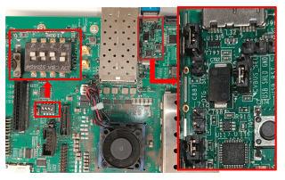
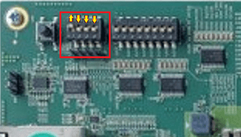
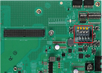
Intel Agilex 7 にジャンパーを設定する
セキュリティ機能を管理するには、Intel Agilex 7 SoC ボード上でセキュア デバイス マネージャー (SDM) を構成する必要があります。SDM をすでに構成している場合は、この手順をスキップし、ハードウェアを接続する前に S9 スイッチの位置をオン-オン-オフ-オフに設定します。
S9とその他のスイッチの位置
| ジャンパー | ポジションを切り替える | |||
|---|---|---|---|---|
| スイッチ1 | スイッチ2 | スイッチ3 | スイッチ4 | |
| SDMを設定する前のS9 | オン | オン | オン | オフ |
| SDMを設定した後のS9 | オン | オン | オフ | オフ |
| S4 | オン | オン | オン | オン |
| S15 | オン | オン | オン | オフ |
| S10 | オン | オン | オン | オン |
| S23 | オン | オン | オン | オン |
| S6 | オフ | オフ | オフ | オフ |
| S1 | オフ | オフ | オフ | オフ |
| S22 | オン | オン | オン | オン |
| S19 | オフ | オフ | オン | オン |
| S20 | オン | オン | オン | オン |

Versal VCK190 のジャンパーを設定する
SW1 スイッチの位置
| Switch | スイッチの位置 |
|---|---|
| 1 | 上 |
| 2 | 下 |
| 3 | 下 |
| 4 | 下 |
ZCU102のジャンパーを設定する
SW6 スイッチの位置
| Switch | スイッチの位置 |
|---|---|
| 1 | 上 |
| 2 | 下 |
| 3 | 下 |
| 4 | 下 |
USBイーサネット構成のジャンパーを設定する
| ジャンパー | ジャンパーポジション |
|---|---|
| J7 | オフ |
| J113 | 1-2 |
| J110 | 1-2 |
| J109 | ジャンパーなし |
ZCU111のジャンパーを設定する
SW6 スイッチの位置
| Switch | スイッチの位置 |
|---|---|
| 1 | 上 |
| 2 | 下 |
| 3 | 下 |
| 4 | 下 |
ZCU216のジャンパーを設定する
SW2 スイッチの位置
| Switch | スイッチの位置 |
|---|---|
| 1 | 上 |
| 2 | 下 |
| 3 | 下 |
| 4 | 下 |
ZC702のジャンパーを設定する
JTAG ジャンパー位置の選択
| Switch | スイッチの位置 |
|---|---|
| 上 | 左 |
| 下 | 右 |
SW10 ジャンパー位置
| Switch | スイッチの位置 |
|---|---|
| 1 | 下 |
| 2 | 下 |
| 3 | 上 |
| 4 | 上 |
| 5 | 下 |
USBイーサネット構成のジャンパーを設定する
| ジャンパー | ジャンパーポジション |
|---|---|
| J7 | オフ |
| J33 | 1-2 |
| J35 | 1-2 |

ZC706のジャンパーを設定する
SW11 ジャンパー位置
| Switch | スイッチの位置 |
|---|---|
| 1 | 下 |
| 2 | 下 |
| 3 | 上 |
| 4 | 上 |
| 5 | 下 |
USBイーサネット構成のジャンパーを設定する
| ジャンパー | ジャンパーポジション |
|---|---|
| J10 | オフ |
| J48 | 1-2 |
| J50 | 1-2 |

ZedBoardにジャンパーを設定する
ジャンパーポジション
| Switch | スイッチの位置 |
|---|---|
| 1 | 下 |
| 2 | 上 |
| 3 | 上 |
| 4 | 下 |
| 5 | 下 |
USBイーサネット構成のジャンパーを設定する
| ジャンパー | ジャンパーポジション |
|---|---|
| JP3 | 開く |

ハードウェアを接続する
この手順は、USB イーサネット インターフェイスまたは Versal または Zynq SoC ボード上のイーサネット インターフェイスを選択する場合にのみ必要です。
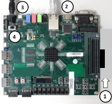
ハードウェアを接続するには、次の手順に従ってください。ガイド付きセットアップ ウィザードでは、各ボードの手順を示すラベル付きの画像が提供されます。
SD カードをホスト コンピューターから取り外し、ハードウェア ボードに挿入します。
イーサネット インターフェイス - イーサネット ケーブルをボードに接続します。イーサネット ケーブルのもう一方の端を、選択した NIC に接続します。
USB イーサネット インターフェイス - USB ケーブルをボードに接続します。USB ケーブルのもう一方の端をホスト コンピューターに接続します。
電源ケーブルを接続します。
電源を入れます。
VCK190ボードを接続する
ZCU102ボードをイーサネットに接続
USBイーサネット用のZCU102ボードを接続する
ZCU111ボードを接続する
ZCU216ボードをイーサネットに接続
USBイーサネット用のZCU216ボードを接続する
ZC702ボードをイーサネットに接続
USBイーサネット用のZC702ボードを接続する
ZC706ボードをイーサネットに接続

USBイーサネット用のZC706ボードを接続する
イーサネット用にZedBoardを接続する
USBイーサネット用にZedBoardを接続する

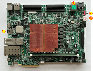
Intel Agilex 7 を接続
この手順は、Intel Agilex 7 SoC ボードでイーサネット インターフェイスを選択する場合にのみ必要です。
SDM を構成するには、S9 スイッチの位置をオン-オン-オン-オフに設定し、次の手順に従います。
JTAGケーブルをボードに接続します。
電源ケーブルをボードに接続し、電源を入れます。
MATLAB コマンド ウィンドウでこのコマンドを実行して、JTAG ケーブル経由で SDM をプログラムします。
programSDM
ボードの電源をオフにし、S9 スイッチの位置をオン-オン-オフ-オフに設定します。
Intel Agilex 7 SoC ボードで SDM を構成する

SDM を設定した後、または SDM の設定をスキップする場合は、S9 スイッチの位置をオン-オン-オフ-オフに設定し、次の手順に従ってハードウェアを接続します。ガイド付きセットアップ ウィザードでは、ボードの手順を示すラベル付きの画像が提供されます。
SD カードをホスト コンピューターから取り外し、ハードウェア ボードに挿入します。
イーサネット ケーブルをボードに接続します。イーサネット ケーブルのもう一方の端を、選択した NIC に接続します。
電源ケーブルを接続します。
電源を入れます。
Intel Agilex 7 SoCボードを接続する

ホストコンピュータでUSBを構成する
この手順は、USB イーサネット インターフェイスを選択した場合にのみ必要です。
ホスト コンピューターをハードウェア ボードと通信できるように構成します。ハードウェア ボード専用の USB イーサネットまたは RNDIS ガジェットと、カードをハードウェア ボードに接続する USB ケーブルが必要です。
ガイド付きセットアップは、Windows オペレーティング システム上の USB 構成のみをサポートします。Linux オペレーティング システムの場合は、Linux を設定する の手順に従って USB イーサネット ガジェットを手動で構成します。
Windows オペレーティング システムの場合、ガイド付きセットアップで、ハードウェア ボードに接続する USB イーサネットまたは RNDIS ガジェットを選択します。USB イーサネット ガジェットをすでに設定している場合は、Skip this step if your USB Ethernet gadget is already configured for communicating with the SoC board を選択します。
ターゲット ハードウェア ボードで SD カードを起動すると、ボードはホスト コンピューターに MathWorks® USB Ethernet または RNDIS ガジェットとして表示されます。
リストには、ホスト コンピューターで検出された接続された NIC が表示されます。接続されている USB イーサネット ガジェットもこのリストに含まれます。メニュー オプションでは、各ガジェットが (In Use) または (Available) として表示されます。ガジェットがデバイスに接続され、IP アドレスが割り当てられている場合、インストーラーはガジェットを (In Use) としてマークします。
USB イーサネット ガジェットがリストに表示されない場合は、Refresh をクリックしてガジェットの検出をトリガーし、リストを更新します。リストを更新すると、たとえば、このペインを表示しているときに USB イーサネット ケーブルを接続するときに便利です。
リストされているすべての USB イーサネット ガジェットが使用中の場合は、ガジェットを解放して Refresh をクリックします。
NIC リストが空の場合、VMWare ソフトウェアが存在すると、NIC 検出が妨げられる可能性があります。ホスト コンピュータ上の NIC の正確なリストを取得するには、VMWare ソフトウェアを削除します。
コントロール パネルで、不足している USB イーサネット ガジェットが無効になっているかどうかを確認します。USB イーサネット ガジェットが無効になっている場合は、有効にします。
USB デバイスと USB ホストの IP アドレスはデフォルトのままにします。あるいは、ドライブを選択してファームウェアをロードする ステップで、USB デバイスの IP アドレスをドット区切りの 4 つの形式で指定することもできます (例: 10.10.10.2)。Next をクリックすると、ソフトウェアはこれらのネットワーク構成に基づいてホスト コンピューター上の USB イーサネット インターフェイスを構成します。
セットアップの確認
イーサネット、JTAG、USB イーサネット インターフェイスのハードウェア設定を確認できます。このステップでは、選択したインターフェイスに基づいて、ホスト コンピューターとハードウェア ボード間の接続を確認するためのテストを実行します。テストを実行する前に、次の点を確認してください。
適切なベンダー ツールがインストールされており、そのツールが MATLAB パス上にあること。FPGA設計ソフトウェアツールのセットアップを参照してください。
ボードの電源がオンになっています。
このステップでは、選択したインターフェースの接続を確認するためにこれらのテストを実行します。
イーサネット
ハードウェア ボード用の FPGA プログラミング ファイルを生成します。
FPGA をプログラムします。
イーサネット接続を検出します。
Versal または Intel Agilex 7 SoC ボード上のイーサネット
ホスト コンピューターの IP アドレス構成を確認します。
ホスト コンピューターとハードウェア ボード間のイーサネット接続を確認します。
デフォルトの SD カード イメージ ビットストリームを使用して、ハードウェア ボード上のメモリ位置を読み書きします。
Zynq SoC ボード上のイーサネット
ホスト コンピューターの IP アドレス構成を確認します。
ホスト コンピューターとハードウェア ボード間のイーサネット接続を確認します。
AXI マネージャーを使用して、ハードウェア ボード上のメモリ位置を読み書きします。
JTAG
ボード用の FPGA プログラミング ファイルを生成します。
FPGA をプログラムします。
FPGA とホスト コンピュータ間のデータ トランザクションを実行します。
USBイーサネット
ホスト コンピューターの IP アドレス構成を確認します。
ホスト コンピューターとハードウェア ボード間のイーサネット接続を確認します。
デフォルトの SD カード イメージ ビットストリームを使用して、ハードウェア ボード上のメモリ位置を読み書きします。
接続が成功しない場合、最も一般的な原因は、ボードが正しく接続されていないか、ボードの電源がオンになっていないことです。ケーブルの接続と電源スイッチを確認して、もう一度お試しください。
例を開きます
インストーラーがハードウェアのセットアップを完了したら、インストーラーを終了するか、サンプルを開いて開始することができます。