Simulation 3D Fisheye Camera
Fisheye camera sensor model in 3D simulation environment
Libraries:
UAV Toolbox /
Simulation 3D
Automated Driving Toolbox /
Simulation 3D
Simulink 3D Animation /
Simulation 3D /
Sensors
Description
Note
Simulating models with the Simulation 3D Fisheye Camera block requires Simulink® 3D Animation™ and Computer Vision Toolbox™.
The Simulation 3D Fisheye Camera block provides an interface to a camera with a fisheye lens in a 3D simulation environment. This environment is rendered using the Unreal Engine® from Epic Games®. The sensor is based on the fisheye camera model proposed by Scaramuzza [1]. This model supports a field of view of up to 195 degrees. The block outputs an image with the specified camera distortion and size. You can also output the location and orientation of the camera in the world coordinate system of the scene.
If you set Sample time to -1, the block uses the
sample time specified in the Simulation 3D Scene Configuration block. To use
this sensor, you must include a Simulation 3D Scene Configuration block in your
model.
Tip
The Simulation 3D Scene Configuration
block must execute before the Simulation 3D Fisheye Camera block. That way,
the Unreal Engine 3D visualization environment prepares the data before the Simulation 3D
Fisheye Camera block receives it. To check the block execution order, right-click
the blocks and then click the Properties button ![]() . On the General tab, confirm these
Priority settings:
. On the General tab, confirm these
Priority settings:
Simulation 3D Scene Configuration —
0Simulation 3D Fisheye Camera —
1
For more information about execution order, see How Unreal Engine Simulation for Automated Driving Works.
The Coordinate system parameter of the block specifies how the actor transformations are applied in the 3D environment. The output of the block also follows the specified coordinate system.
Examples
Simulate Simple Driving Scenario and Sensor in Unreal Engine Environment
Learn the basics of configuring and simulating scenes, vehicles, and sensors in a virtual environment rendered using the Unreal Engine from Epic Games.
Ports
Input
Output
Parameters
Tips
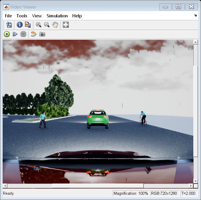
To visualize the camera images that are output by the Image port, use a Video Viewer or To Video Display block.
Because the Unreal Engine can take a long time to start up between simulations, consider logging the signals that the sensors output. You can then use this data to develop perception algorithms in MATLAB. See Mark Signals for Logging (Simulink).
You can also save image data as a video by using a To Multimedia File block. For an example of this setup, see Design Lane Marker Detector Using Unreal Engine Simulation Environment.
Algorithms
References
[1] Scaramuzza, D., A. Martinelli, and R. Siegwart. "A Toolbox for Easy Calibrating Omnidirectional Cameras." Proceedings to IEEE International Conference on Intelligent Robots and Systems (IROS 2006). Beijing, China, October 7–15, 2006.