Design Lane Marker Detector Using Unreal Engine Simulation Environment
This example shows how to use a 3D simulation environment to record synthetic sensor data, develop a lane marker detection system, and test that system under different scenarios. This simulation environment is rendered using the Unreal Engine® from Epic Games®.
Overview
Developing a reliable perception system can be very challenging. A visual perception system must be reliable under a variety of conditions, especially when it is used in a fully automated system that controls a vehicle. This example uses a lane detection algorithm to illustrate the process of using the 3D simulation environment to strengthen the design of the algorithm. The main focus of the example is the effective use of the 3D simulation tools rather than the algorithm itself. Therefore, this example reuses the perception algorithms from the Visual Perception Using Monocular Camera example.
The Visual Perception Using Monocular Camera example uses recorded video data to develop a visual perception system that contains lane marker detection and classification, vehicle detection, and distance estimation. Use of the recorded video is a great start, but it is inadequate for exploring many other cases that can be more easily synthesized in a virtual environment. More complex scenarios can include complex lane change maneuvers, occlusion of lane markers due to other vehicles, and so on. Most importantly, closed-loop simulation involves both perception and control of the vehicle, both of which require either a virtual environment or a real vehicle. Additionally, testing up front with a real vehicle can be expensive, thus making the use of a 3D simulation environment very attractive.
This example takes the following steps to familiarize you with an approach to designing a visual perception algorithm:
Introduces you to the 3D simulation environment in Simulink®
Guides you through the setup of a virtual vehicle and camera sensor
Shows you how to effectively set up a debugging environment for your visual perception algorithm
Presents how to increase scene complexity in preparation for closed-loop simulation
Introduction to the 3D Simulation Environment
Automated Driving Toolbox™ integrates a 3D simulation environment in Simulink. The 3D simulation environment uses the Unreal Engine by Epic Games. Simulink blocks related to the 3D simulation environment provide the ability to:
Select different scenes in the 3D visualization engine
Place and move vehicles in the scene
Attach and configure sensors on the vehicles
Simulate sensor data based on the environment around the vehicle
The Simulink blocks for 3D simulation can be accessed by opening drivingsim3d library.
To aid in the design of visual perception algorithms in this example, you use a block that defines a scene, a block that controls a virtual vehicle, and a block that defines a virtual camera. The example focuses on detecting lane markers using a monocular camera system.
Create a Simple Straight Road Scene in 3D Simulation
Get a list of systems that are open now so any systems opened during this example can be closed at the end.
startingOpenSystems = find_system('MatchFilter', @Simulink.match.allVariants);
Start by defining a simple scenario involving a straight highway road on which to exercise the lane marker detection algorithm.
open_system('straightRoadSim3D');

The Simulation 3D Scene Configuration block lets you choose one of the predefined scenes, in this case Straight Road. When the model is invoked, it launches the Unreal Engine®. The Simulation 3D Vehicle with Ground Following block creates a virtual vehicle within the gaming engine and lets Simulink take control of its position by supplying X and Y in meters, and Yaw in degrees. X, Y, and Yaw are specified with respect to a world coordinate system, with an origin in the middle of the scene. In this case, since the road is straight, an offset of 0.75 meters in the Y-direction and a series of increasing X values move the vehicle forward. Later sections of this example show how to define more complex maneuvers without resorting to X, Y, and Yaw settings based on trial and error.
The model also contains a Simulation 3D Camera block, which extracts video frames from a virtual camera attached at the rearview mirror within the virtual vehicle. The camera parameters let you simulate typical parameters of a camera that can be described by a pinhole camera model, including focal length, camera optical center, radial distortion, and output image size. When the model is invoked, the resulting scene is shown from a perspective of a camera that automatically follows the vehicle.
sim('straightRoadSim3D');

Design and Debugging of Visual Perception Module
Visual perception is generally complex, whether it involves classic computer vision or deep learning. Developing such a system often requires rapid iterations with incremental refinements. Although Simulink is a powerful environment for system-level engineering and closed-loop simulations, perception-based algorithms are typically developed in textual programming languages like MATLAB or C++. Additionally, the startup time for a model that needs to establish communication between Simulink and the Unreal Engine® is significant. For these reasons, it is convenient to record the image data generated by the virtual camera into a video and develop the perception algorithm in MATLAB. The following model records the camera into an MP4 file on disk.
open_system('straightRoadVideoRecording');
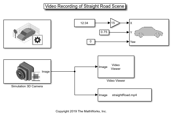
The video is recorded using the To Multimedia File block. The resulting straightRoad.mp4 file can now be used to develop the perception module, without incurring the startup-time penalty of the 3D simulation environment.
To design the lane marker detector, you use a module from the Visual Perception Using Monocular Camera example. However, if you simply transplant the existing helperMonoSensor.m routine from that example, even the simplest straight road scene does not produce good results. Immediately, you can see how powerful the virtual environment can be. You can choose any trajectory or environment for your vehicle, thus letting you explore many what-if scenarios prior to placing the perception module on an actual vehicle.
To aid in the design of the algorithm, use the provided HelperLaneDetectorWrapper.m system object. This system object works in MATLAB and when placed inside the Create Custom Blocks Using MATLAB System Block and System objects (Simulink) in Simulink. The following script, helperStraightRoadMLTest, invokes the wrapper from the MATLAB command prompt. This approach permits quick iterations of the design without continuous invocation of the 3D simulation environment.
helperStraightRoadMLTest

Once the algorithm begins to work well, you can place it back into a model as shown below. You can attempt to change the car's trajectory, as demonstrated in the Select Waypoints for Unreal Engine Simulation example. That way, you can look for ways to move the car such that the algorithm fails. The entire process is meant to be iterative.
open_system('straightRoadMonoCamera');

Navigate Through a More Complex Scene to Improve the Perception Algorithm
While developing your algorithm, you can increase the level of scene complexity to continue adapting your system to conditions resembling reality. In this section, switch the scene to Virtual Mcity, which provides stretches of the road with curved lanes, no lane markers, or merging lane markers. You must install the Virtual Mcity scene using the Add-On Installer dialog box from the Simulation 3D Scene Configuration block. For more information on setting up the Virtual Mcity scene for simulation, see Virtual Mcity.
Before you begin, you need to define a trajectory through a suitable stretch of the virtual Mcity, which is a representation of actual testing grounds that belong to the University of Michigan. To see the details of how to obtain a series of X, Y, and Yaw values suitable for moving a car through a complex environment, refer to the Select Waypoints for Unreal Engine Simulation example. The key steps are summarized below for your convenience.
% Extract scene image location based on scene's name
sceneName = 'VirtualMCity';
[sceneImage, sceneRef] = helperGetSceneImage(sceneName);
% Interactively select waypoints through Mcity
helperSelectSceneWaypoints(sceneImage, sceneRef)
% Convert the sparse waypoints into a denser trajectory that a car can
% follow
numPoses = size(refPoses, 1);
refDirections  = ones(numPoses,1);   % Forward-only motion
numSmoothPoses = 20 * numPoses;      % Increase this to increase the number of returned poses
[newRefPoses,~,cumLengths] = smoothPathSpline(refPoses, refDirections, numSmoothPoses);
% Create a constant velocity profile by generating a time vector
% proportional to the cumulative path length
simStopTime = 10;
timeVector = normalize(cumLengths, 'range', [0, simStopTime]);
refPosesX   = [timeVector, newRefPoses(:,1)];
refPosesY   = [timeVector, newRefPoses(:,2)];
refPosesYaw = [timeVector, newRefPoses(:,3)];
Load the preconfigured vehicle poses created using the method shown above.
poses = load('mcityPoses');
With the predefined trajectory, you can now virtually drive the vehicle through a longer stretch of a complex virtual environment.
open_system('mcityMonoCamera');
sim('mcityMonoCamera');
clear poses;

Many times, the results are less than desirable. For example, notice where the barriers are confused with lane markers and when the region of interest selected for analysis is too narrow to pick up the left lane.

However, the detector performs well in other areas of the scene.

The main point is that the virtual environment lets you stress-test your design and helps you realize what kind of conditions you may encounter on real roads. Running your algorithm in a virtual environment also saves you time. If your design does not run successfully in the virtual environment, then there is no point of running it in a real vehicle on a road, which is far more time-consuming and expensive.
Closed-Loop Testing
One of the most powerful features of a 3D simulation environment is that it can facilitate closed-loop testing of a complex system. Lane keep assist, for example, involves both perception and control of the vehicle. Once a perception system is perfected on very complex scenes and performs well, it can then be used to drive a control system that actually steers the car. In this case, rather than manually set up a trajectory, the vehicle uses the perception system to drive itself. It is beyond the scope of this example to show the entire process. However, the steps described here should provide you with ideas on how to design and debug your perception system so it can later be used in a more complex closed-loop simulation.
% Close any systems opened during execution of this example.
endingOpenSystems = find_system('MatchFilter', @Simulink.match.allVariants);
bdclose(setdiff(endingOpenSystems,startingOpenSystems))
See Also
Blocks
- Simulation 3D Scene Configuration | Simulation 3D Vehicle with Ground Following | Simulation 3D Camera | Simulation 3D Fisheye Camera
Topics
- Generate Code for Lane Marker Detector
- Automate Testing for Lane Marker Detector
- Select Waypoints for Unreal Engine Simulation
- Highway Lane Following
- Choose a Sensor for Unreal Engine Simulation
- Simulate Simple Driving Scenario and Sensor in Unreal Engine Environment
- Depth and Semantic Segmentation Visualization Using Unreal Engine Simulation
- Unreal Engine Simulation for Automated Driving