Main Content

Simulation 3D Vehicle with Ground Following

Implement vehicle that follows ground in 3D environment

Since R2019b

  • Simulation 3D Vehicle with Ground Following block

Libraries:
Automated Driving Toolbox / Simulation 3D
Vehicle Dynamics Blockset / Vehicle Scenarios / Sim3D / Sim3D Vehicle / Components

Description

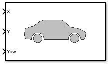
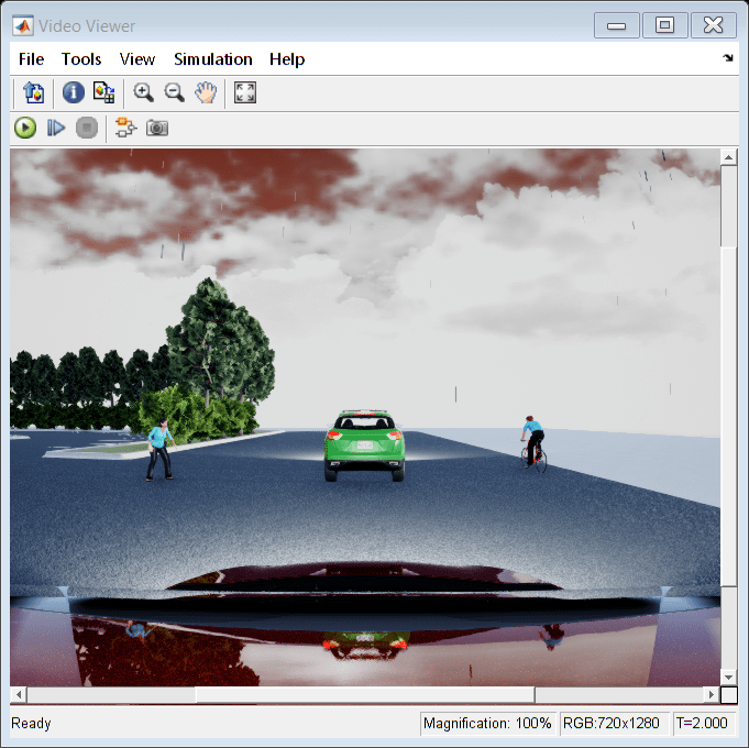
The Simulation 3D Vehicle with Ground Following block implements a vehicle with four wheels in a 3D simulation environment. This environment is rendered using the Unreal Engine® from Epic Games®. The block uses the input (X, Y) position and yaw angle of the vehicle to adjust the elevation, roll angle, and pitch angle of the vehicle so that it follows the ground terrain. The block determines the vehicle velocity and heading and adjusts the steering angle and rotation for each wheel. Use this block for automated driving applications.

To use this block, ensure that the Simulation 3D Scene Configuration block is in your model. If you set the Sample time parameter of the Simulation 3D Vehicle with Ground Following block to -1, the block inherits the sample time specified in the Simulation 3D Scene Configuration block.

The block input uses the vehicle Z-up right-handed (RH) Cartesian coordinate system defined in SAE J670 [1] and ISO 8855 [2]. The coordinate system is inertial and initially aligned with the vehicle geometric center:

  • The X-axis is along the longitudinal axis of the vehicle and points forward.

  • The Y-axis is along the lateral axis of the vehicle and points to the left.

  • The Z-axis points upward.

The yaw, pitch, and roll angles of the Z-axis, Y-axis, and X-axis, respectively, are positive in the clockwise directions, when looking in the positive directions of these axes. Vehicles are placed in the world coordinate system of the scenes. For more details, see Coordinate Systems for Unreal Engine Simulation in Automated Driving Toolbox.

Note

The Simulation 3D Vehicle with Ground Following block must execute before the Simulation 3D Scene Configuration block. That way, the Simulation 3D Vehicle with Ground Following block prepares the signal data before the Unreal Engine 3D visualization environment receives it. To check the block execution order, right-click the blocks and select Properties. On the General tab, confirm these Priority settings:

  • Simulation 3D Scene Configuration0

  • Simulation 3D Vehicle with Ground Following-1

For more information about execution order, see How Unreal Engine Simulation for Automated Driving Works.

You can configure the Simulation 3D Vehicle with Ground Following block to import custom meshes and control vehicle lights.

Limitations

  • The Bird's-Eye Scope is unable to find ground truth signals, such as roads, lanes, and actors, from the Simulation 3D Scene Configuration block.

Ports

Input

expand all

Longitudinal position of the vehicle along the X-axis of the scene. X is in the inertial Z-up coordinate system. Units are in meters.

The X value of the Initial position [X, Y, Z] (m) parameter must match the value of this port at the start of simulation.

To specify multiple positions at port X along an entire vehicle path, first define a time series of X waypoints in MATLAB®. Then, feed these waypoints to X by using a From Workspace (Simulink) block. To learn how to select and specify waypoints, see the Select Waypoints for Unreal Engine Simulation example.

Lateral position of the vehicle along the Y-axis of the scene. Y is in the inertial Z-up coordinate system. Units are in meters.

The Y value of the Initial position [X, Y, Z] (m) parameter must match the value of this port at the start of simulation.

To specify multiple positions at port Y along an entire vehicle path, first define a time series of Y waypoints in MATLAB. Then, feed these waypoints to Y by using a From Workspace (Simulink) block. To learn how to select and specify waypoints, see the Select Waypoints for Unreal Engine Simulation example.

Yaw orientation angle of the vehicle along the Z-axis of the scene. Yaw is in the Z-up coordinate system. Units are in degrees.

The yaw value of the Initial rotation [Roll, Pitch, Yaw] (deg) parameter must match the value of this port at the start of simulation.

To specify multiple orientation angles at port Yaw along an entire vehicle path, first define a time series of yaw waypoints in MATLAB. Then, feed these waypoints to Yaw by using a From Workspace (Simulink) block. To learn how to select and specify waypoints, see the Select Waypoints for Unreal Engine Simulation example.

Light controls input signal, specified as a 1-by-6 Boolean vector. Each element of the vector turns a specific vehicle light on or off, as indicated in this table. A value of 1 turns the light on; a value of 0 turns the light off

Vector ElementVehicle Light

(1,1)

Headlight high beam

(1,2)

Headlight low beam

(1,3)

Brake

(1,4)

Reverse

(1,5)

Left signal

(1,6)

Right signal

Dependencies

To create this port, on the Light Controls tab, select Enable light controls.

Data Types: Boolean

Output

expand all

(X, Y, Z) location of the vehicle in the scene, returned as a real-valued 1-by-3 vector. This location is based on the vehicle origin, which is on the ground, at the geometric center of the vehicle. Location values are in the inertial Z-up world coordinate system. Units are in meters.

Dependencies

To enable this port, on the Ground Truth tab, select Output location (m) and orientation (rad).

Data Types: double

Yaw, pitch, and roll orientation angles of the vehicle about the Z-axis, Y-axis, and X-axes of the scene, respectively, returned as a real-valued 1-by-3 vector. This orientation is based on the vehicle origin, which is on the ground, at the geometric center of the vehicle. Orientation values are in the inertial Z-up coordinate system. Units are in radians.

Dependencies

To enable this port, on the Ground Truth tab, select Output location (m) and orientation (rad).

Data Types: double

Parameters

expand all

Vehicle Parameters

Select the type of vehicle. To obtain the dimensions of each vehicle type, see these reference pages:

Dependencies

Selecting Custom enables parameters that allow you to import a custom mesh for your vehicle.

Path to custom mesh.

To create a custom vehicle mesh, see Prepare Custom Vehicle Mesh for the Unreal Editor.

Example: /MathWorksSimulation/Vehicles/Muscle/Meshes/SK_Sedan.SK_Sedan

Dependencies

To enable this parameter, set Type to Custom.

Track width in custom mesh, in m.

Dependencies

To enable this parameter, set Type to Custom.

Wheel base in custom mesh, in m.

Dependencies

To enable this parameter, set Type to Custom.

Wheel radius in custom mesh, in m.

Dependencies

To enable this parameter, set Type to Custom.

Select the color of the vehicle.

Initial vehicle position along the X-axis, Y-axis, and Z-axis of the scene. This position is in the inertial Z-up coordinate system. Units are in meters.

Set the X and Y values of this parameter to match the X and Y input port values at the start of simulation.

Initial angle of vehicle rotation. The angle of rotation is defined by the roll, pitch, and yaw of the vehicle. Units are in degrees.

Set the yaw value of this parameter to match the Yaw input port value at the start of simulation.

Name of vehicle. By default, when you use the block in your model, the block sets the Name parameter to SimulinkVehicleX. The value of X depends on the number of Simulation 3D Vehicle with Ground Following blocks that you have in your model.

The vehicle name appears as a selection in the Parent name parameter of any Automated Driving Toolbox™ Simulation 3D sensor blocks within the same model as the vehicle. With the Parent name parameter, you can select the vehicle on which to mount the sensor.

Sample time, Ts, in seconds. The graphics frame rate is the inverse of the sample time.

If you set the sample time to -1, the block uses the sample time specified in the Simulation 3D Scene Configuration block.

Light Controls

Select whether to control the vehicle headlights. Use the enabled parameters to set the light parameters, including headlight intensity.

Dependencies

Selecting this parameter:

  • Creates the input port Light controls

  • Enables these light parameters.

    LightsLight Parameters
    Headlights

    • Headlight color

    • High beam intensity

    • Low beam intensity

    • High beam cone half angle

    • Low beam cone half angle

    • Left headlight beam orientation

    • Right headlight beam orientation

    Brake lights

    Brake light intensity

    Reverse lights

    Reverse light intensity

    Turn signal lights

    • Turn signal light intensity

    • Period

    • Pulse width

Headlights

Headlight color, specified as a normalized 1-by-3 array of RGB triplet values.

Dependencies

To enable this parameter, select Enable light controls.

Data Types: int8 | uint8

High beam intensity, in cd.

Dependencies

To enable this parameter, select Enable light controls.

Data Types: double

Low beam intensity, in cd.

Dependencies

To enable this parameter, select Enable light controls.

Data Types: double

High beam cone half angle, in deg.

Dependencies

To enable this parameter, select Enable light controls.

Data Types: double

Low beam cone half angle, in deg.

Dependencies

To enable this parameter, select Enable light controls.

Data Types: double

Pitch and yaw orientation of the left headlight beam orientation in the Z-up coordinate system, specified as a 1-by-2 array, in deg. The first element of the array, [1,1], is the pitch angle. The second element of the array, [1,2] is the yaw angle.

Dependencies

To enable this parameter, select Enable light controls.

Data Types: double

Pitch and yaw orientation of the right headlight beam orientation in the Z-up coordinate system, specified as a 1-by-2 array, in deg. The first element of the array, [1,1], is the pitch angle. The second element of the array, [1,2] is the yaw angle.

Dependencies

To enable this parameter, select Enable light controls.

Brake Lights

Brake light intensity, in cd/m^2.

Dependencies

To enable this parameter, select Enable light controls.

Data Types: double

Reverse Lights

Reverse light intensity, in cd/m^2.

Dependencies

To enable this parameter, select Enable light controls.

Data Types: double

Turn Signal Lights

Turn signal light intensity, in cd/m^2.

Dependencies

To enable this parameter, select Enable light controls.

Data Types: double

Turn signal light period, in s.

Dependencies

To enable this parameter, select Enable light controls.

Data Types: double

Turn signal light pulse width, as a percent of the period.

Dependencies

To enable this parameter, select Enable light controls.

Data Types: double

Ground Truth

Select this parameter to output the location and orientation of the vehicle at the Location and Orientation ports, respectively.

More About

expand all

References

[1] Vehicle Dynamics Standards Committee. Vehicle Dynamics Terminology. SAE J670. Warrendale, PA: Society of Automotive Engineers, 2008.

[2] Technical Committee. Road vehicles — Vehicle dynamics and road-holding ability — Vocabulary. ISO 8855:2011. Geneva, Switzerland: International Organization for Standardization, 2011.

Version History

Introduced in R2019b