nrCDLChannel
CDL MIMO チャネルのモデル化
説明
nrCDLChannel System object™ は、クラスター遅延線 (CDL) 多入力多出力 (MIMO) リンクレベル フェージング チャネルをモデル化します。
このオブジェクトは、TR 38.901 [1]および TR 38.811 [2]の次の項目を実装します。
TR 38.901 の Section 7.7.1: CDL モデル
TR 38.901 の Section 7.7.3: 遅延のスケーリング
TR 38.901 の Section 7.7.5.1: 角度のスケーリング
TR 38.901 の Section 7.7.6: LOS チャネル モデルの K ファクター
TR 38.901 の Section 7.6.10: デュアル モビリティ (R2023b 以降)
TR 38.811 の Section 6.9.1: 非地上ネットワーク (NTN) の CDL モデル (R2026a 以降)
このオブジェクトは、既定で CDL チャネルのフィルター処理を有効にします。CDL チャネルのフィルター処理を有効にすると、チャネルを経由して入力信号を送信し、チャネルで劣化した信号を取得することができます。既定のオブジェクトは、フェージング プロセスのパス ゲイン、およびチャネル スナップショットのサンプル時間も返します。
このオブジェクトでは、ChannelResponseOutput プロパティを 'ofdm-response' に設定すると、OFDM チャネル応答とタイミング オフセットを取得することもできます。この場合、このオブジェクトは、次の図に示すように、入力信号に加えてキャリア入力を受け取り、パス ゲインとサンプル時間の代わりに OFDM チャネル応答とタイミング オフセットを返します。 (R2024b 以降)

チャネルを経由して信号を送信することなくチャネル特性を取得するには、ChannelFiltering プロパティを false に設定します。
オブジェクトのプロパティを使用して CDL チャネルのフィルター処理とチャネル係数生成を構成する方法の概要については、CDL チャネル モデルの内部アーキテクチャを参照してください。
予期せぬ結果となったリンクレベル シミュレーションをデバッグするために、DelayProfile プロパティを 'None' に設定することでチャネル劣化要因を無効にすることができます。チャネルのこの動作に関する詳細については、チャネル劣化要因が無効化された CDL チャネル モデルを参照してください。 (R2026a 以降)
CDL MIMO チャネル モデルを使用するには、次のようにします。
nrCDLChannelオブジェクトを作成し、そのプロパティを設定する。関数と同じように、引数を付けてオブジェクトを呼び出す。
System object の仕組みについては、System object とはを参照してください。
作成
構文
説明
cdl = nrCDLChannel
cdl = nrCDLChannel(PropertyName=Value)DelayProfile='CDL-D' は、CDL-D 遅延プロファイルをもつチャネル オブジェクトを作成します。
cdl = nrCDLChannel(DelayProfile='Custom',InitialDelayProfile=profile,DelaySpread=spread,KFactor=K)profile から初期化されるカスタマイズされたチャネル特性をもつオブジェクトを作成します。profile 入力を、'CDL-A'、'CDL-B'、'CDL-C'、'CDL-D'、または 'CDL-E' として指定します。 (R2023b 以降)
この構文を使用した場合、次のようになります。
DelayProfileオブジェクト プロパティは'Custom'に設定されます。また、AnglesAoD、AnglesAoA、AnglesZoD、AnglesZoA、HasLOSCluster、KFactorFirstCluster、AngleSpreads、およびXPRの各オブジェクト プロパティは、TR 38.901 の Table 7.7.1-1 ~ 7.7.1-5[1] で指定された事前定義済み遅延プロファイルに対して定義されている値に設定されます。PathDelaysプロパティとAveragePathGainsプロパティの値は、初期テーブル値からスケーリングされ、それぞれ秒単位のspreadで指定された目的のチャネル遅延スプレッドと、dB 単位のKで指定された K ファクターが取得されます。オプションのspread入力とK入力を数値スカラーとして指定します。指定しない場合、spread入力は既定で30e-9になります。K入力は、既定で TR 38.901 の Table 7.7.1-4 ~ 7.7.1-5 の K ファクターの値に設定されます (K ファクターのスケーリングなし)。K入力は、profile入力が'CDL-D'または'CDL-E'に設定されている場合にのみ適用されます。
プロパティ
特に断りがない限り、プロパティは "調整不可" です。すなわち、オブジェクトを呼び出した後にその値を変更することはできません。オブジェクトは呼び出し時にロックされ、関数 release によってロックが解除されます。
プロパティが "調整可能" な場合は、その値をいつでも変更できます。
プロパティ値の変更に関する詳細については、System object を使用した MATLAB でのシステム設計を参照してください。
遅延プロファイルの選択
遅延プロファイルの選択により、どの遅延プロファイル構成プロパティがチャネルに適用されるかが決まります。
TR 38.901 の Section 7.7.1、Table 7.7.1-1 ~ 7.7.1-5、および TR 38.811 の Section 7.7.1、Table 6.9.1-1 ~ 6.9.1-4 の CDL 遅延プロファイル。次のいずれかのオプションとして指定します。
'CDL-A'、'CDL-B'、'CDL-C'、'CDL-D'、'CDL-E'— これらの事前定義済み遅延プロファイルに固有なチャネル パラメーターを構成するには、事前定義された遅延プロファイルのセクションを参照してください。'NTN-CDL-A'、'NTN-CDL-B'、'NTN-CDL-C'、'NTN-CDL-D'— TR 38.811 の Section 6.9.1 で規定されたこれらの事前定義済み NTN 遅延プロファイルに固有なチャネル パラメーターを構成するには、事前定義された遅延プロファイルのセクションを参照してください。 (R2026a 以降)'Custom'— カスタム遅延プロファイルに固有なチャネル パラメーターを構成するには、カスタム遅延プロファイルのセクションを参照してください。'None'— チャネル劣化要因を無効にします。このオプションは、エラー ベクトル振幅 (EVM)、スループット、ブロック エラー レート (BLER) などのシミュレーション結果が期待値から逸脱し、その根本原因を特定したい場合に使用します。チャネル劣化要因の無効化が CDL チャネルの動作にどのように影響するかの概要については、チャネル劣化要因が無効化された CDL チャネル モデルを参照してください。 (R2026a 以降)
データ型: char | string
事前定義された遅延プロファイル
これらのプロパティは、事前定義されたチャネル プロファイルに固有なチャネル パラメーター (DelayProfile を 'CDL-A'、'CDL-B'、'CDL-C'、'CDL-D'、'CDL-E'、'NTN-CDL-A'、'NTN-CDL-B'、'NTN-CDL-C'、または 'NTN-CDL-D' に設定した場合のチャネル パラメーター) を構成します。
RMS 遅延スプレッド目標値 (秒)。非負の実数として指定します。RMS 遅延スプレッド目標値 DSdesired の例については、TR 38.901 の Section 7.7.3 および Table 7.7.3-1 と 7.7.3-2 を参照してください。既定値は 30 ナノ秒です。
依存関係
このプロパティを有効にするには、DelayProfile を 'CDL-A'、'CDL-B'、'CDL-C'、'CDL-D'、'CDL-E', 'NTN-CDL-A'、'NTN-CDL-B'、'NTN-CDL-C'、または 'NTN-CDL-D' に設定します。このプロパティはカスタム遅延プロファイルには適用されません。
データ型: double
K ファクターのスケーリング。false または true として指定します。true に設定した場合、KFactor プロパティによって K ファクター目標値が指定され、TR 38.901 の Section 7.7.6 の説明に従いオブジェクトによって K ファクターのスケーリングが適用されます。
メモ
K ファクターのスケーリングにより、パス遅延とパス電力の両方が変更されます。
依存関係
このプロパティを有効にするには、DelayProfile を 'CDL-D'、'CDL-E'、'NTN-CDL-C'、または 'NTN-CDL-D' に設定します。
データ型: double
スケーリング用の K ファクター目標値 (dB)。数値スカラーとして指定します。一般的な K ファクターの値については、TR 38.901 の Section 7.7.6 および Table 7.5-6 を参照してください。
メモ
K ファクターのスケーリングにより、パス遅延とパス電力の両方が変更されます。
K-factorは、遅延プロファイル全体に適用されます。特に、TR 38.901 の Section 7.7.6 で説明されているように、スケーリング前の K ファクターはKmodelになります。Kmodelは、最初のパスの LOS の電力と、最初のクラスターのラプラシアン パートを含むすべてのラプラシアン クラスターの総電力との比です。
依存関係
このプロパティを有効にするには、KFactorScaling を true に設定します。
データ型: double
角度のスケーリングの適用。TR 38.901 の Section 7.7.5.1 に従って、false または true として指定します。true に設定した場合、AngleSpreads プロパティと MeanAngles プロパティによって角度のスケーリングが定義されます。
依存関係
このプロパティを有効にするには、DelayProfile を 'CDL-A'、'CDL-B'、'CDL-C'、'CDL-D'、'CDL-E', 'NTN-CDL-A'、'NTN-CDL-B'、'NTN-CDL-C'、または 'NTN-CDL-D' に設定します。このプロパティはカスタム遅延プロファイルには適用されません。
データ型: logical
スケーリングされた平均角度 (度)。[AoD AoA ZoD ZoA] の形式の 4 要素行ベクトルとして指定します。
AoD は、スケーリング後の発射角の平均方位角。
AoA は、スケーリング後の到来角の平均方位角。
ZoD は、スケーリング後の発射角の平均天頂角。
ZoA は、スケーリング後の到来角の平均天頂角。
TR 38.901 の Section 7.7.5.1 および TR 38.811 の Section 6.9.1 で説明されているように、このベクトルを使用して、角度のスケーリングに使用するチャネルの平均角度目標値 () を指定します。
メモ
NTN 遅延プロファイルが 'NTN-CDL-A'、'NTN-CDL-B'、'NTN-CDL-C'、および 'NTN-CDL-D' である場合、スケーリングは到来角にのみ適用されます。
依存関係
このプロパティを有効にするには、AngleScaling を true に設定します。
データ型: double
カスタム遅延プロファイル
これらのプロパティは、カスタム遅延プロファイルに固有なチャネル パラメーター (DelayProfile を 'Custom' に設定した場合のチャネル パラメーター) を構成します。
離散パスの遅延 (秒)。数値スカラーまたは行ベクトルとして指定します。AveragePathGains と PathDelays は同じサイズでなければなりません。
調整可能: Yes
依存関係
このプロパティを有効にするには、DelayProfile を 'Custom' に設定します。
データ型: double
平均パス ゲイン (dB)。TR 38.901 ではクラスター電力とも呼ばれます。数値スカラーまたは行ベクトルとして指定します。AveragePathGains と PathDelays は同じサイズでなければなりません。HasLOSCluster プロパティが true に設定されている場合、このオブジェクトは、このプロパティの最初の要素を 2 つの部分に分割します。これらの部分は、最初のクラスターの LOS パートと NLOS パートに対応します。次に、このオブジェクトは、KFactorFirstCluster プロパティを使用して、最初のクラスターの LOS パートと NLOS パートの電力配分を決定します。
調整可能: Yes
依存関係
このプロパティを有効にするには、DelayProfile を 'Custom' に設定します。
データ型: double
到来角の方位角 (度)。数値スカラーまたは行ベクトルとして指定します。このベクトルの要素は、各クラスターの角度を指定します。
調整可能: Yes
依存関係
このプロパティを有効にするには、DelayProfile を 'Custom' に設定します。
データ型: double
発射角の方位角 (度)。数値スカラーまたは行ベクトルとして指定します。このベクトルの要素は、各クラスターの角度を指定します。
調整可能: Yes
依存関係
このプロパティを有効にするには、DelayProfile を 'Custom' に設定します。
データ型: double
到来角の天頂角 (度)。数値スカラーまたは行ベクトルとして指定します。このベクトルの要素は、各クラスターの角度を指定します。
調整可能: Yes
依存関係
このプロパティを有効にするには、DelayProfile を 'Custom' に設定します。
データ型: double
発射角の天頂角 (度)。数値スカラーまたは行ベクトルとして指定します。このベクトルの要素は、各クラスターの角度を指定します。
調整可能: Yes
依存関係
このプロパティを有効にするには、DelayProfile を 'Custom' に設定します。
データ型: double
遅延プロファイルの見通し線 (LOS) クラスター。false または true として指定します。PathDelays、AveragePathGains、AnglesAoA、AnglesAoD、AnglesZoA、および AnglesZoD の各プロパティは、遅延プロファイルを定義します。遅延プロファイルの LOS クラスターを有効にするには、HasLOSCluster を true に設定します。
依存関係
このプロパティを有効にするには、DelayProfile を 'Custom' に設定します。
データ型: logical
遅延プロファイルの最初のクラスターの K ファクター (dB)。数値スカラーとして指定します。既定値は、TR 38.901 の Section 7.7.1、Table 7.7.1-4 で定義されている CDL-D の最初のクラスターの K ファクターに対応します。
依存関係
このプロパティを有効にするには、DelayProfile を 'Custom' に設定し、HasLOSCluster を true に設定します。
データ型: double
スケーリングされた (またはクラスター単位の) 平方根平均二乗 (RMS) 角度スプレッド (度)。次のいずれかの形式の 4 要素行ベクトルとして指定します。
[ASD ASA ZSD ZSA] — TR 38.901 の Section 7.7.5.1 で説明されているように、このベクトルを使用して、チャネルの RMS 角度スプレッド目標値 (ASdesired) を指定します。ここで、以下のようになります。
ASD は、発射角の RMS 方位角スプレッド。
ASA は、到来角の RMS 方位角スプレッド。
ZSD は、発射角の RMS 天頂角スプレッド。
ZSA は、到来角の RMS 天頂角スプレッド。
この形式を使用するには、
AngleScalingをtrueに設定し、DelayProfileを'CDL-A'、'CDL-B'、'CDL-C'、'CDL-D'、または'CDL-E'に設定します。[CASD CASA CZSD CZSA] — TR 38.901 の Section 7.7.1 の Step1 で説明されているように、このベクトルを使用して、クラスター内の光線オフセット角をスケーリングするためのクラスター単位の RMS 角度スプレッドを指定します。ここで、以下のようになります。
CASD は、発射角のクラスター単位の RMS 方位角スプレッド。
CASA は、到来角のクラスター単位の RMS 方位角スプレッド。
CZSD は、発射角のクラスター単位の RMS 天頂角スプレッド。
CZSA は、到来角のクラスター単位の RMS 天頂角スプレッド。
この形式を使用するには、
DelayProfileを'Custom'に設定します。この場合、TR 38.901 の Section 7.7.5.1 に基づいて、このオブジェクトは角度のスケーリングを実行しません。
既定値は、TR 38.901 の Section 7.7.1 の Table 7.7.1-1 で定義されている CDL-A のクラスターごとの既定の角度スプレッドに対応しています。
依存関係
このプロパティを有効にするには、DelayProfile を 'Custom' に設定するか、AngleScaling を true に設定します。
データ型: double
方位角と天頂角に関するクラスター内の発射光線と到来光線の結合。次のいずれかの値として指定します。
'Random'— このオブジェクトは、TR 38.901 の Section 7.5 の Step 8 で定義されているように、RandomStreamプロパティで指定された乱数ストリームを使用して、光線をランダムに結合します。N×M×3 の数値配列 — この配列を使用して、光線の結合を明示的に定義します。N はクラスターの数で、
PathDelaysプロパティで指定されたパス遅延の数と同じです。M はクラスターあたりの光線の数で、値は 20 です。3 次元の 3 つの N×M 平面は、それぞれ AoD/AoA、ZoD/ZoA、および AoD/ZoD の光線結合に対応しています。各 N×M 平面の各行は、1 から M までの光線インデックスの順列を使用して、対応するクラスター内の光線結合を指定します。メモ
N は、サブクラスターに分割される前のクラスターの数です (
NumStrongestClustersプロパティを参照)。N は、
HasLOSClusterプロパティによって指定された LOS クラスターをカウントしません。
依存関係
このプロパティを有効にするには、DelayProfile を 'Custom' に設定します。
データ型: double | char | string
交差偏波電力比 (dB)。数値スカラー、または N 行 M 列の数値行列として指定します。N はクラスターの数で、PathDelays プロパティで指定されたパス遅延の数と同じです。M はクラスターあたりの光線の数で、値は 20 です。既定値は、TR 38.901 の Section 7.7.1、Table 7.7.1-1 で定義されている CDL-A のクラスターごとの交差偏波電力比に対応しています。
メモ
N は、サブクラスターに分割される前のクラスターの数です (
NumStrongestClustersプロパティを参照)。N は、
HasLOSClusterプロパティによって指定された LOS クラスターをカウントしません。
依存関係
このプロパティを有効にするには、DelayProfile を 'Custom' に設定します。
データ型: double
4 つの偏波の組み合わせに対するすべての光線の初期位相 (度)。次のいずれかの値として指定します。
'Random'— このオブジェクトは、TR 38.901 の Section 7.5 の Step 10 で定義されているように、RandomStreamプロパティで指定された乱数ストリームを使用して、一様分布するランダムな位相を描画します。N×M×4 の数値配列 — このオプションを使用して、初期位相を明示的に定義します。N はクラスターの数で、
PathDelaysプロパティで指定されたパス遅延の数と同じです。M はクラスターあたりの光線の数で、値は 20 です。3 次元の 4 つの N×M 平面は、それぞれ θ/θ、θ/ϕ、ϕ/θ、および ϕ/ϕ の偏波の組み合わせに対応しています。メモ
N は、サブクラスターに分割される前のクラスターの数です (
NumStrongestClustersプロパティを参照)。N は、
HasLOSClusterプロパティによって指定された LOS クラスターをカウントしません。
調整可能: Yes
依存関係
このプロパティを有効にするには、DelayProfile を 'Custom' に設定します。
データ型: double | char | string
サブクラスターに分割する最も強いクラスターの数。非負の整数として指定します。HasLOSCluster プロパティが true に設定されている場合、このオブジェクトは最初のクラスターを LOS パートと NLOS パートに分割します。分割後の NLOS パートの平均パス ゲインが AveragePathGains プロパティで指定されたいずれかの値よりも大きい場合、NLOS パートはさらに 3 つのサブクラスターに分割されます。詳細については、TR 38.901 の Section 7.5 の Step 11 を参照してください。
依存関係
このプロパティを有効にするには、DelayProfile を 'Custom' に設定します。
データ型: double
クラスターの遅延スプレッド (秒)。非負の実数として指定します。このプロパティを使用して、サブクラスターに分割されたクラスターのサブクラスター間の遅延オフセットを指定します。TR 38.901 の Section 7.5 の Step 11 を参照してください。
依存関係
このプロパティを有効にするには、DelayProfile を 'Custom' に設定し、NumStrongestClusters を 0 より大きい値に設定します。
データ型: double
アンテナ アレイ
これらのプロパティは、チャネルの幾何学的側面を構成します。
送信アンテナ アレイの特性。構造体またはフェーズド アレイとして指定します (Phased Array System Toolbox™ が必要)。info オブジェクト関数を使用すると、アンテナの数を取得できます。
フェーズド アレイを使用すると、事前定義済みアンテナ素子やカスタム アンテナ素子など、さまざまなアンテナ アレイ構成を指定できます。Phased Array System Toolbox または Antenna Toolbox™ の機能を使用して、カスタム アンテナ素子を設計できます。TR 38.901 の Section 7.3 で定義されている 5G 矩形マルチパネル アレイ内のカスタム アンテナ素子を指定するには、phased.NRRectangularPanelArray (Phased Array System Toolbox) オブジェクトを使用します。フェーズド アレイの概要については、アレイのジオメトリおよび解析 (Phased Array System Toolbox)を参照してください。
構造体として指定した場合、このプロパティには次の表に記載されているフィールドが格納されます。
| パラメーター フィールド | 値 | 説明 |
|---|---|---|
Size |
行ベクトル | アンテナ アレイのサイズ。[M N P Mg Ng] として指定します。ここで、以下のようになります。
アンテナ アレイ全体は Mg 行 Ng 列のアンテナ パネルで構成され、各アンテナ パネルのサイズは M 行 N 列です。P = 1 の場合、偏波角はすべてのアンテナ アレイ素子で同じになります。P = 2 の場合、アンテナ アレイ素子の半分は 1 つの偏波角をもち、残りの半分は別の偏波角をもちます。
たとえば、次の図は、このオブジェクトが入力信号
|
ElementSpacing |
行ベクトル | 素子の間隔 (波長)。[λv λh dgv dgh] の形式の行ベクトルとして指定します。このベクトルの要素は、それぞれ、垂直方向と水平方向の素子の間隔、および垂直方向と水平方向のパネルの間隔を表します。パネルの間隔はパネルの中心から測定されます。 |
PolarizationAngles |
行ベクトル | 偏波角 (度)。[θ ρ] の形式の行ベクトルとして指定します。 |
Orientation (削除予定) |
列ベクトル | メモ このフィールドは将来のリリースで削除される予定です。代わりに アレイの機械的な向き (度)。[α; β; γ] の形式の列ベクトルとして指定します。このベクトルの要素は、それぞれ方位、ダウンチルト、傾斜を指定します。既定値は、アレイのブロードサイドの向きが x 軸の正の向きを指すことを示します。 |
Element |
| TR 38.901 の Section 7.3 および TR 38.811 に記載されているアンテナ素子の放射パターン。(TR 38.901 は TR 38.900 に取って代わることに注意してください。)
|
PolarizationModel |
| 定義された放射電力パターンに基づいて放射界のパターンを決定するモデル。詳細については、TR 38.901 の Section 7.3.2 を参照してください。 |

送信アンテナ アレイの機械的な向き。[α; β; γ] の形式の 3 要素数値列ベクトルとして指定します。このベクトルの要素は、TR 38.901 の Section 7.1.3 で指定されているように、それぞれ方位角、ダウンチルト角、および傾斜の回転角を度単位で指定します。このオブジェクトは、ローカル座標系の既定のアレイの向きを基準にしてこれらの回転角を適用します。このオブジェクトがこれらの回転角を適用する方法の詳細については、アンテナ アレイの機械的な向きを参照してください。
値 [0; 0; 0] に対応するアレイの既定の向きは、TransmitAntennaArray プロパティによって異なります。
TransmitAntennaArrayプロパティを構造体 (既定) として指定した場合、既定のアレイの向きにおいて、ブロードサイドの向きは x 軸の正の向きを指します。TransmitAntennaArrayプロパティをフェーズド アレイとして指定した場合 (Phased Array System Toolbox が必要)、指定したフェーズド アレイ オブジェクトに関連するアレイ プロパティを設定することで、既定のアレイの向きを構成できます。
結果として得られるアレイの向きを可視化して評価するには、 チャネル モデルで displayChannel 関数を呼び出します。
送信アンテナと受信アンテナを向かい合わせた場合の例については、LOS パス角度を使用した送信アンテナと受信アンテナの向きの決定を参照してください。
調整可能: Yes
依存関係
このプロパティを有効にするには、DelayProfile を 'None' 以外の値に設定します。
データ型: double
受信アンテナ アレイの特性。構造体またはフェーズド アレイ (Phased Array System Toolbox が必要) として指定します。info オブジェクト関数を使用すると、アンテナの数を取得できます。
フェーズド アレイを使用すると、事前定義済みアンテナ素子やカスタム アンテナ素子など、さまざまなアンテナ アレイ構成を指定できます。Phased Array System Toolbox または Antenna Toolbox の機能を使用して、カスタム アンテナ素子を設計できます。TR 38.901 の Section 7.3 で定義されている 5G 矩形マルチパネル アレイ内のカスタム アンテナ素子を指定するには、phased.NRRectangularPanelArray (Phased Array System Toolbox) オブジェクトを使用します。フェーズド アレイの概要については、アレイのジオメトリおよび解析 (Phased Array System Toolbox)を参照してください。
構造体として指定した場合、このプロパティには次の表に記載されているフィールドが格納されます。
| パラメーター フィールド | 値 | 説明 |
|---|---|---|
Size |
行ベクトル | アンテナ アレイのサイズ。[M N P Mg Ng] として指定します。ここで、以下のようになります。
アンテナ アレイ全体は Mg 行 Ng 列のアンテナ パネルで構成され、各アンテナ パネルのサイズは M 行 N 列です。P = 1 の場合、偏波角はすべてのアンテナ アレイ素子で同じになります。P = 2 の場合、アンテナ アレイ素子の半分は 1 つの偏波角をもち、残りの半分は別の偏波角をもちます。
たとえば、次の図は、このオブジェクトがサイズ
|
ElementSpacing |
行ベクトル | 素子の間隔 (波長)。[λv λh dgv dgh] の形式の行ベクトルとして指定します。このベクトルの要素は、それぞれ、垂直方向と水平方向の素子の間隔、および垂直方向と水平方向のパネルの間隔を表します。パネルの間隔はパネルの中心から測定されます。 |
PolarizationAngles |
行ベクトル | 偏波角 (度)。[θ ρ] の形式の行ベクトルとして指定します。 |
Orientation (削除予定) |
列ベクトル | メモ このフィールドは将来のリリースで削除される予定です。代わりに アレイの機械的な向き (度)。[α; β; γ] の形式の列ベクトルとして指定します。このベクトルの要素は、それぞれ方位、ダウンチルト、傾斜を指定します。既定値は、アレイのブロードサイドの向きが x 軸の正の向きを指すことを示します。 |
Element |
| TR 38.901 の Section 7.3 および TR 38.811 に記載されているアンテナ素子の放射パターン。(TR 38.901 は TR 38.900 に取って代わることに注意してください。)
|
PolarizationModel |
| 定義された放射電力パターンに基づいて放射界のパターンを決定するモデル。詳細については、TR 38.901 の Section 7.3.2 を参照してください。 |
受信アンテナ アレイの機械的な向き。[α; β; γ] の形式の 3 要素数値列ベクトルとして指定します。このベクトルの要素は、TR 38.901 の Section 7.1.3 で指定されているように、それぞれ方位角、ダウンチルト角、および傾斜の回転角を度単位で指定します。このオブジェクトは、ローカル座標系の既定のアレイの向きを基準にしてこれらの回転角を適用します。このオブジェクトがこれらの回転角を適用する方法の詳細については、アンテナ アレイの機械的な向きを参照してください。
値 [0; 0; 0] に対応するアレイの既定の向きは、ReceiveAntennaArray プロパティによって異なります。
ReceiveAntennaArrayプロパティを構造体 (既定) として指定した場合、既定のアレイの向きにおいて、ブロードサイドの向きは x 軸の正の向きを指します。ReceiveAntennaArrayプロパティをフェーズド アレイとして指定した場合 (Phased Array System Toolbox が必要)、指定したフェーズド アレイ オブジェクトに関連するアレイ プロパティを設定することで、既定のアレイの向きを構成できます。
結果として得られるアレイの向きを可視化して評価するには、 チャネル モデルで displayChannel 関数を呼び出します。
送信アンテナと受信アンテナを向かい合わせた場合の例については、LOS パス角度を使用した送信アンテナと受信アンテナの向きの決定を参照してください。
調整可能: Yes
依存関係
このプロパティを有効にするには、DelayProfile を 'None' 以外の値に設定します。
データ型: double
データ型: double
モビリティ
これらのプロパティは、送信機または受信機の移動方法を構成します。
最大ドップラー シフト (Hz)。次のいずれかの値として指定します。
非負の実数 — この値は受信機の最大ドップラー シフトを指定します。
UTDirectionOfTravelプロパティが 2 行 2 列の行列として指定されている場合、この値は受信機と送信機の最大ドップラー シフトを指定します。[Rx Tx] という形式の 1 行 2 列の非負の実数ベクトル — Rx と Tx は、それぞれ受信機と送信機の最大ドップラー シフトを指定します。 (R2023b 以降)
このプロパティはすべてのチャネル パスに適用されます。最大ドップラー シフトが 0 に設定されている場合、入力全体でチャネルは静的なままとなります。新しいチャネル実現を生成するには、reset 関数を呼び出してオブジェクトをリセットします。
調整可能: Yes
依存関係
このプロパティを有効にするには、DelayProfile を 'None' 以外の値に設定します。
データ型: double
ユーザー端末 (またはユーザー機器) の移動方向 (度)。次のいずれかの値として指定します。
実数から成る [RxA; RxZ] の形式の 2 行 1 列のベクトル — RxA と RxZ は、それぞれ受信側 UE の移動方向の方位角と天頂角を指定します。
MaximumDopplerShiftプロパティが 1 行 2 列のベクトルとして指定されている場合、RxA と RxZ は、受信側 UE と送信側 UE について、それぞれ移動方向の方位角と天頂角を指定します。実数から成る [RxA, TxA; RxZ, TxZ] の形式の 2 行 2 列の行列 — RxA と RxZ は、それぞれ受信側 UE の移動方向の方位角と天頂角を指定します。TxA と TxZ は、それぞれ送信側 UE の移動方向の方位角と天頂角を指定します。 (R2023b 以降)
調整可能: Yes
依存関係
このプロパティを有効にするには、DelayProfile を 'None' 以外の値に設定します。
データ型: double
R2023b 以降
チャネル内の移動散乱体の割合。範囲 [0, 1] の実数として指定します。このプロパティを 0 に設定した場合、いずれの散乱体も移動しない指定になります。このプロパティを 1 に設定した場合、すべての散乱体が移動する指定になります。このオブジェクトは、RandomStream プロパティの設定に基づいて、移動散乱体をランダムに選択します。このプロパティは、デュアルモビリティ構成にのみ適用されます。
依存関係
このプロパティを有効にするには、DelayProfile を 'None' 以外の値に設定し、MaximumDopplerShift プロパティを 1 行 2 列のベクトルに設定するか、UTDirectionOfTravel プロパティを 2 行 2 列の行列に設定します。
データ型: double
R2023b 以降
チャネル内の移動散乱体の最大速度 (m/s)。非負の実数として指定します。このプロパティは、デュアルモビリティ構成にのみ適用されます。
依存関係
このプロパティを有効にするには、DelayProfile を 'None' 以外の値に設定し、MaximumDopplerShift プロパティを 1 行 2 列のベクトルに設定するか、UTDirectionOfTravel プロパティを 2 行 2 列の行列に設定します。
データ型: double
R2026a 以降
地上 UE から衛星へのパス仰角 (度)。範囲 [0 90] の数値スカラーとして指定します。
SatelliteElevationAngle プロパティを 50 度以外の値に設定すると、オブジェクトはチャネルの到来天頂角と発射天頂角を更新します。
調整可能: Yes
依存関係
このプロパティを有効にするには、DelayProfile プロパティを 'NTN-CDL-A'、'NTN-CDL-B'、'NTN-CDL-C'、または 'NTN-CDL-D' に設定します。
データ型: double
チャネル制御
これらのプロパティは、TR 38.901 で定義されていないチャネルの実装に固有のパラメーターを構成します。たとえば、チャネルのフィルター処理を有効または無効にしたり、フィルター処理された信号のデータ型とサンプル数を設定したり、パス ゲイン生成の制御パラメーターを設定したりすることができます。
データ型: double
フェージング プロセスの時間オフセット (秒)。非負の実数として指定します。
調整可能: Yes
依存関係
このプロパティを有効にするには、DelayProfile を 'None' 以外の値に設定します。
データ型: double
半波長あたりの時間サンプル数。Inf または正の実数として指定します。SampleDensity プロパティおよび MaximumDopplerShift プロパティは、係数生成サンプリング レート Fcg を制御します。これは次の式で表されます。
Fcg = (sum(MaximumDopplerShift) + (2 × (MaximumScattererSpeed/lambda0))) × 2 × SampleDensity。ここで、lambda0 はキャリア波長です。
SampleDensity を Inf に設定した場合、Fcg に SampleRate プロパティの値が割り当てられます。
サンプル密度がチャネルの出力とパス ゲインにどのように影響するかの例については、CDL チャネル出力における SampleDensity プロパティの効果を参照してください。
依存関係
このプロパティを有効にするには、DelayProfile を 'None' 以外の値に設定します。
データ型: double
一様分布乱数を使用して光線の位相と結合を初期化する乱数ストリームのソース。次の値のいずれかとして指定します。
依存関係
このプロパティを有効にするには、DelayProfile を 'None' 以外の値に設定し、RayCoupling プロパティまたは InitialPhases プロパティを 'Random' に設定するか、オブジェクトをデュアルモビリティで構成します。デュアルモビリティを構成するには、MaximumDopplerShift プロパティを 1 行 2 列のベクトルに設定するか、UTDirectionOfTravel プロパティを 2 行 2 列の行列に設定します。
mt19937ar 乱数ストリームの初期シード。非負の数値スカラーとして指定します。
依存関係
このプロパティを有効にするには、DelayProfile を 'None' 以外の値に設定し、RandomStream を 'mt19937ar with seed' に設定します。reset 関数を呼び出すと、シードによって mt19937ar 乱数ストリームが再初期化されます。
データ型: double
チャネル出力の正規化。true または false として指定します。このプロパティが true に設定されている場合、チャネル出力信号は受信アンテナの数の平方根で除算されます。正規化は NR によって行われます。ここで、NR は受信アンテナ素子の数またはアンテナ サブアレイの数です (ReceiveAntennaArray プロパティを phased.ReplicatedSubarray (Phased Array System Toolbox) または phased.PartitionedArray (Phased Array System Toolbox) フェーズド アレイ オブジェクトとして指定した場合のみ)。NR の値を特定するには、info(cdl)NumOutputSignals 構造体フィールドを確認します。
メモ
swapTransmitAndReceive 関数を呼び出してチャネル内の送信アンテナと受信アンテナの役割を入れ替えると、この関数によって info(cdl)
NumTransmitAntennasおよびNumReceiveAntennasNumInputSignalsおよびNumOutputSignals
したがって、正規化は常に NR によって行われます。
データ型: logical
正規化されたチャネル フェージング プロセス。true または false として指定します。このプロパティが true に設定されている場合、チャネル フェージング プロセスの振幅は平均パス ゲイン (TR 38.901 ではクラスター電力とも呼ばれます) によって正規化されます。この正規化には、偏波やアンテナ素子の指向性など、他のチャネル ゲインは含まれません。このプロパティが false に設定されている場合、チャネル フェージング プロセスは正規化されません。DelayProfile プロパティは、TR 38.901 の Section 7.7.1、Table 7.7.1-1 ~ 7.7.1-5 に基づいて平均パス ゲインを決定します。DelayProfile を 'Custom' に設定した場合、AveragePathGains プロパティを使用して平均パス ゲインを指定できます。
依存関係
このプロパティを有効にするには、DelayProfile を 'None' 以外の値に設定します。
データ型: logical
R2024b 以降
チャネル応答出力。次のいずれかのオプションとして指定します。
'path-gains'— 次の図に示すように、オブジェクトはパス ゲインとサンプル時間を返します。チャネルのフィルター処理が有効になっている場合、オブジェクトはフィルター処理された出力信号も返します。または、パス ゲインとサンプル時間のみを返すようにチャネルを構成するには、ChannelFilteringプロパティをfalseに設定してチャネルのフィルター処理を無効にします。
'ofdm-response'— 次の図に示すように、キャリア入力を指定してオブジェクトを呼び出すと、このオブジェクトは OFDM チャネル応答とタイミング オフセットを返します。チャネルのフィルター処理が有効になっている場合、オブジェクトはフィルター処理された出力信号も返します。または、OFDM チャネル応答とタイミング オフセットのみを返すようにチャネルを構成するには、ChannelFilteringプロパティをfalseに設定してチャネルのフィルター処理を無効にします。
データ型: string | char
フェージング チャネルのフィルター処理。次のいずれかのオプションとして指定します。
true— チャネルのフィルター処理を有効にします。オブジェクトは入力信号を受け取り、チャネルによってフィルター処理を行います。false— チャネルのフィルター処理を無効にします。オブジェクトは入力信号を受け取らず、ChannelResponseOutputプロパティに応じて OFDM チャネル応答とタイミング オフセット (R2024b 以降)またはパス ゲインとサンプル時間のみを返します。チャネルのフィルター処理を無効にすると、次の条件が適用されます。
NumTimeSamplesプロパティは、SampleRateプロパティによって与えられたサンプル レートでフェージング プロセス実現の持続時間を制御します。OutputDataTypeプロパティは、生成されたチャネル応答出力 (OFDM チャネル応答またはパス ゲイン) のデータ型を指定します。
このプロパティがチャネルの内部アーキテクチャにどのように影響するかの概要については、CDL チャネル モデルの内部アーキテクチャを参照してください。
チャネルのフィルター処理を無効にするユース ケースについては、CDL チャネルの OFDM チャネル応答の計算の例を参照してください。
データ型: logical
R2026a 以降
チャネルのフィルター処理が無効になっている場合の GPU 処理の有効化。次のいずれかの値として指定します。
'off'— オブジェクトが CPU 上で実行されます。'on'— オブジェクトが GPU 上で実行され、すべての出力が GPU 上のgpuArray(Parallel Computing Toolbox) オブジェクトとして返されます。'auto'— GPU を利用できる場合、オブジェクトが自動的に GPU 上で実行され、すべての出力が GPU 上のgpuArrayオブジェクトとして返されます。GPU を利用できない場合、オブジェクトは CPU 上で実行されます。
GPU を使用して MATLAB® での計算を高速化するには、Parallel Computing Toolbox™ およびサポートされている GPU デバイスが必要です。サポートされているデバイスの詳細については、GPU 計算の要件 (Parallel Computing Toolbox)を参照してください。
依存関係
このプロパティを有効にするには、ChannelFiltering プロパティを false に設定します。
データ型: char | string
時間サンプルの数。正の整数として指定します。チャネルのフィルター処理が無効になっている場合は、このプロパティを使用してフェージング プロセス実現の持続時間を設定できます。
キャリア入力 carrier を使用してオブジェクトを呼び出す場合は、NumTimeSamples プロパティをスロット内のサンプル数以上の値に設定します。nrOFDMInfo(carrier) の出力構造からスロット内のサンプル数を計算できます。 (R2024b 以降)
調整可能: Yes
依存関係
このプロパティを有効にするには、DelayProfile を 'None' 以外の値に設定し、ChannelFiltering を false に設定します。
データ型: double
生成されたチャネル応答出力のデータ型。'double' または 'single' として指定します。チャネルのフィルター処理が無効になっている場合は、このプロパティを使用し、ChannelResponseOutput プロパティに応じて OFDM チャネル応答 (R2024b 以降)またはパス ゲインのデータ型を指定します。
依存関係
このプロパティを有効にするには、ChannelFiltering を false に設定します。
読み取り専用のプロパティ
この プロパティ は読み取り専用です。
チャネル リンク方向の反転。次の値のいずれかとして返されます。
false— チャネル モデル内の送信アンテナと受信アンテナの役割は、元のチャネル リンク方向に対応します。nrCDLChannelオブジェクトに対してswapTransmitAndReceive関数を呼び出すと、チャネルのリンク方向が反転し、このプロパティの値がfalseからtrueに切り替わります。true— チャネル モデル内の送信アンテナと受信アンテナの役割が入れ替わります。nrCDLChannelオブジェクトに対して関数swapTransmitAndReceiveを呼び出すと、チャネルの元のリンク方向が復元され、このプロパティの値がtrueからfalseに切り替わります。
データ型: logical
使用法
構文
説明
OFDM チャネル応答とタイミング オフセット
R2024b 以降
これらの構文を使用するには、ChannelResponseOutput プロパティを 'ofdm-response' に設定します。
[ は、指定されたキャリア signalOut,ofdmResponse] = cdl(signalIn,carrier)carrier に基づいてチャネル インパルス応答に OFDM 復調を適用し、チャネルで劣化した信号に加えて OFDM チャネル応答を返します。この出力は、チャネルが OFDM 信号の各リソース エレメントにどのように影響するかを示します。
[ は、チャネルのインパルス応答が最も強いパスのタイミング オフセットも返します。チャネルのインパルス応答は、すべてのチャネル スナップショットにわたって平均化され、すべての送信アンテナと受信アンテナにわたって加算されます。signalOut,ofdmResponse,timingOffset] = cdl(signalIn,carrier)
[ は、入力信号をフィルター処理せずに、OFDM チャネル応答とタイミング オフセットのみを返します。ofdmResponse,timingOffset] = cdl(carrier)cdl オブジェクトと carrier 入力は、OFDM チャネル応答とタイミング オフセットの計算のソースとして機能します。この構文を使用するには、ChannelFiltering プロパティも false に設定しなければなりません。
パス ゲインとサンプル時間
これらの構文を使用するには、ChannelResponseOutput プロパティを 'path-gains' に設定します (R2024b 以降)。
[ は、signalOut,pathGains,sampleTimes] = cdl(signalIn)pathGains (最初の次元の要素) のチャネル スナップショットのサンプル時間も返します。
[ は、入力信号をフィルター処理せずに、パス ゲインとサンプル時間のみを返します。pathGains,sampleTimes] = cdl()cdl オブジェクトは、パス ゲインとサンプル時間の計算のソースとして機能します。この構文を使用するには、ChannelFiltering プロパティも false に設定しなければなりません。
入力引数
出力引数
オブジェクト関数
オブジェクト関数を使用するには、最初の入力引数として System object を指定します。たとえば、obj という名前の System object のシステム リソースを解放するには、次の構文を使用します。
release(obj)
例
既定のキャリア構成オブジェクトを作成します。
carrier = nrCarrierConfig;
CDL-B 遅延プロファイルを使用して CDL チャネル オブジェクトを作成します。
channel = nrCDLChannel;
channel.DelayProfile = "CDL-B";
channel.MaximumDopplerShift = 200;
搬送波のサンプル レートと一致するように、チャネルのサンプル レートを設定します。
ofdmInfo = nrOFDMInfo(carrier);
channel.SampleRate = ofdmInfo.SampleRate;
OFDM チャネル応答をチャネルの出力として指定します。
channel.ChannelResponseOutput = "ofdm-response";チャネル フィルター処理を無効にします。
channel.ChannelFiltering = false;
単一スロットの OFDM 応答を生成するための時間サンプルの数を設定します。
channel.NumTimeSamples = sum(ofdmInfo.SymbolLengths(1:carrier.SymbolsPerSlot));
キャリア入力を指定して CDL チャネル オブジェクトを呼び出します。このオブジェクトは、CDL チャネルの OFDM チャネル応答とタイミング オフセットを返します。
[ofdmResponse,timingOffset] = channel(carrier);
OFDM チャネル応答を表示します。
mesh(abs(ofdmResponse(:,:,1,1)));
title('OFDM Channel Response of CDL Channel');
xlabel('OFDM Symbol'); ylabel("Subcarrier"); zlabel("Magnitude");

TR 38.901 の Section 7.7.1 の遅延プロファイル CDL-D を使用し、クラスター遅延線 (CDL) チャネル モデルを経由して波形を送信します。
nrCDLChannel System object を使用して、チャネル構成の構造体を定義します。遅延プロファイル CDL-D、遅延スプレッド 10 ns、および UE 速度 15 km/h を使用します。
v = 15.0;                    % UE velocity in km/h
fc = 4e9;                    % carrier frequency in Hz
c = physconst('lightspeed'); % speed of light in m/s
fd = (v*1000/3600)/c*fc;     % UE max Doppler frequency in Hz

cdl = nrCDLChannel;
cdl.DelayProfile = 'CDL-D';
cdl.DelaySpread = 10e-9;
cdl.CarrierFrequency = fc;
cdl.MaximumDopplerShift = fd;
送信アレイのレイアウトを [M N P Mg Ng] = [2 4 2 1 2] の形式のベクトルとして構成します。これは、2 行 4 列のアンテナ アレイ (M = 2、N = 4) と 2 つの偏波角 (P = 2) をもつ 2 つのパネル (Mg = 1、Ng = 2) を表します。受信アンテナ アレイを [M N P Mg Ng] = [1 1 2 1 1] の形式のベクトルとして構成します。これは、同じ場所に配置された交差偏波アンテナの単一のペアを表します。
cdl.TransmitAntennaArray.Size = [2 4 2 1 2];
cdl.ReceiveAntennaArray.Size = [1 1 2 1 1];
送信アンテナ素子間の距離を半波長に設定します。すべてのパネルのアンテナ素子が均等に配分され、なおかつパネルが重ならないように、アンテナ パネルの中心間の距離を指定します。
cdl.TransmitAntennaArray.ElementSpacing(1:2) = 0.5;
cdl.TransmitAntennaArray.ElementSpacing(3:4) = cdl.TransmitAntennaArray.ElementSpacing(1:2).*(cdl.TransmitAntennaArray.Size(1:2));
チャネルを表示して構成を確認します。
displayChannel(cdl,'LinkEnd','Tx')

displayChannel(cdl,'LinkEnd','Rx')

8 つのアンテナでサブフレーム時間 1 のランダムな波形を作成します。
SR = 15.36e6;
T = SR * 1e-3;
cdl.SampleRate = SR;
cdlinfo = info(cdl);
Nt = cdlinfo.NumInputSignals;

txWaveform = complex(randn(T,Nt),randn(T,Nt));
チャネルを介して入力波形を送信します。
rxWaveform = cdl(txWaveform);
nrCDLChannel System object を使用しながら、さまざまなサンプル密度値に対するチャネル出力とパス ゲインのスナップショットをプロットします。
TR 38.901 の Section 7.7.1 の遅延プロファイル CDL-B を使用してチャネルを構成します。最大ドップラー シフトを 300 Hz に設定し、チャネルのサンプル レートを 10 kHz に設定します。
cdl = nrCDLChannel;
cdl.DelayProfile = 'CDL-B';
cdl.MaximumDopplerShift = 300.0;
cdl.SampleRate = 10e3;
cdl.Seed = 19;
送信アンテナ アレイと受信アンテナ アレイを単入力単出力 (SISO) 動作用に構成します。
cdl.TransmitAntennaArray.Size = [1 1 1 1 1];
cdl.ReceiveAntennaArray.Size = [1 1 1 1 1];
長さが 40 サンプルの入力波形を作成します。
T = 40;
in = ones(T,1);
SampleDensity プロパティのさまざまな値に対し、チャネルのステップ応答 (ラインで表示) および対応するパス ゲインのスナップショット (円で表示) をプロットします。サンプル密度プロパティは、ドップラー周波数に応じてチャネルのスナップショット取得頻度を制御します。
SampleDensityをInfに設定すると、入力サンプルごとにチャネル スナップショットが取得されます。SampleDensityをスカラーの "S" に設定すると、チャネルのスナップショットは のレートで取得されます。
nrCDLChannel オブジェクトは、ゼロ次ホールド補間によってチャネルのスナップショットを入力波形に適用します。このオブジェクトは、入力の終端を超えて追加のスナップショットを取得します。最終的な出力サンプルでは、補間誤差を最小限に抑えるためにこの追加の値が使用される場合があります。チャネル出力には、パス遅延を実装するフィルターによる過渡現象 (および遅延) が含まれます。
s = [Inf 5 2]; % sample densities

legends = {};
figure; hold on;
SR = cdl.SampleRate;
for i = 1:length(s)

    % call channel with chosen sample density
    release(cdl); cdl.SampleDensity = s(i);
    [out,pathgains,sampletimes] = cdl(in);
    chInfo = info(cdl); tau = chInfo.ChannelFilterDelay;

    % plot channel output against time
    t = cdl.InitialTime + ((0:(T-1)) - tau).' / SR;
    h = plot(t,abs(out),'o-');
    h.MarkerSize = 2;
    h.LineWidth = 1.5;
    desc = ['Sample Density = ' num2str(s(i))];
    legends = [legends ['Output, ' desc]];
    disp([desc ', Ncs = ' num2str(length(sampletimes))]);

    % plot path gains against sample times
    h2 = plot(sampletimes-tau/SR,abs(sum(pathgains,2)),'o');
    h2.Color = h.Color;
    h2.MarkerFaceColor = h.Color;
    legends = [legends ['Path Gains, ' desc]];
end
Sample Density = Inf, Ncs = 40
Sample Density = 5, Ncs = 13
Sample Density = 2, Ncs = 6
xlabel('Time (s)');
title('Channel Output and Path Gains vs. Sample Density');
ylabel('Channel Magnitude');
legend(legends,'Location','NorthWest');

CDL チャネル モデルを作成します。次に、見通し線 (LOS) チャネルを指定します。
cdl = nrCDLChannel;
cdl.DelayProfile = 'CDL-D'; % LOS channel
cdl.TransmitAntennaArray.Element = '38.901';
cdl.ReceiveAntennaArray.Element = '38.901';
チャネルの特性情報を取得します。特性情報で返された LOS パス角度を使用して、送信アンテナ アレイと受信アンテナ アレイを向かい合わせます。
cdlInfo = cdl.info;
cdl.TransmitArrayOrientation = [cdlInfo.AnglesAoD(1) cdlInfo.AnglesZoD(1)-90 0]';
cdl.ReceiveArrayOrientation = [cdlInfo.AnglesAoA(1) cdlInfo.AnglesZoA(1)-90 0]';
送信機端のチャネル特性を可視化します。
cdl.displayChannel('LinkEnd','Tx');
view(0,90)

受信機端のチャネル特性を可視化します。最も強いパス (LOS) は、アンテナ素子の放射パターンが最大となる点を通過します。これにより、アンテナが向かい合っていることを確認できます。
cdl.displayChannel('LinkEnd','Rx')
view(0,90)

CDL チャネル モデルを作成します。次に、送信アンテナ アレイにフェーズド アレイを指定します。
cdl = nrCDLChannel;
cdl.TransmitAntennaArray = phased.URA;
円偏波界を生成するため、クロスダイポール送信アンテナ アレイ素子を指定します。
cdl.TransmitAntennaArray.Element = phased.CrossedDipoleAntennaElement;
アレイのブロードサイドを y 軸の正の向きに向けます。30 度のダウンチルトを追加します。
cdl.TransmitAntennaArray.ArrayNormal = 'y';
cdl.TransmitArrayOrientation = [0; 30; 0];
アンテナ素子の間隔を半波長に設定します。
lambda = physconst('lightspeed')/cdl.CarrierFrequency;
cdl.TransmitAntennaArray.ElementSpacing = [lambda/2 lambda/2];
送信機端のチャネル特性を可視化します。
cdl.displayChannel('LinkEnd','Tx');

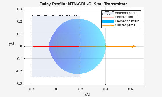
NTN CDL チャネル モデルを作成します。遅延プロファイルを 'NTN-CDL-C' に設定します。
channel = nrCDLChannel;
channel.DelayProfile = 'NTN-CDL-C';
channel.DelaySpread = 30e-9;
channel.CarrierFrequency = 2e9;
channel.SatelliteElevationAngle = 50;
送信アンテナ アレイおよび受信アンテナ アレイにベッセル アンテナを指定します。
channel.TransmitAntennaArray.ElementType = 'bessel';
channel.ReceiveAntennaArray.ElementType = 'bessel';
アンテナ アレイのサイズ、間隔、偏波角を設定します。
channel.TransmitAntennaArray.Size = [1 1 1 1 1];  % 1 row, 5 columns
channel.ReceiveAntennaArray.Size = [1 1 1 1 1];
channel.TransmitAntennaArray.ElementSpacing = [0.5 0.5 0 0];
channel.ReceiveAntennaArray.ElementSpacing = [0.5 0.5 0 0];
channel.TransmitAntennaArray.PolarizationAngles = 0;
channel.ReceiveAntennaArray.PolarizationAngles = 45;
チャネルの特性情報を取得します。特性情報で返された LOS パス角度を使用して、送信アンテナ アレイと受信アンテナ アレイを向かい合わせます。
channelInfo = channel.info;
channel.TransmitArrayOrientation = [channelInfo.AnglesAoD(1) channelInfo.AnglesZoD(1)-90 0]';
channel.ReceiveArrayOrientation = [channelInfo.AnglesAoA(1) channelInfo.AnglesZoA(1)-90 0]';
波形を生成し、その波形を設定済みのチャネルに渡します。
txWaveform = randn(1000, prod(channel.TransmitAntennaArray.Size));
rxWaveform = channel(txWaveform);
送信機端のチャネル特性を可視化します。
displayChannel(channel,'LinkEnd','Tx')
view(0,90)
アルゴリズム
これらのオブジェクト プロパティは、CDL チャネル フィルター処理とチャネル係数の生成を構成します。
CDL チャネルのフィルター処理を有効または無効にするには、ChannelFiltering プロパティを使用します。
CDL チャネルのフィルター処理が有効 —
ChannelFilteringをtrueに設定すると、オブジェクトは入力信号を受け取り、チャネルで劣化した信号を返します。ChannelResponseOutputプロパティに応じて、オブジェクトは次のものも返します。OFDM チャネル応答とタイミング オフセット (
ChannelResponseOutput='ofdm-response'の場合)。 (R2024b 以降)パス ゲインとサンプル時間 (
ChannelResponseOutput='path-gains'の場合)。
次の図は、チャネルのフィルター処理が有効になっており、オブジェクトが OFDM チャネル応答とタイミング オフセットを返す場合の、CDL チャネル モデルの内部アーキテクチャを示しています。 (R2024b 以降)

CDL チャネルのフィルター処理が無効 —
ChannelFilteringをfalseに設定すると、オブジェクトは入力信号を受け取りません。ただし、ChannelResponseOutputプロパティに応じて、オブジェクトは次のものを返します。OFDM チャネル応答とタイミング オフセット (
ChannelResponseOutput='ofdm-response'の場合)。 (R2024b 以降)パス ゲインとサンプル時間 (
ChannelResponseOutput='path-gains'の場合)。
OutputDataTypeプロパティとNumTimeSamplesプロパティを使用して、それぞれチャネル応答出力のデータ型とフェージング プロセス実現の持続時間を設定します。次の図は、チャネルのフィルター処理が無効になっており、オブジェクトが OFDM チャネル応答とタイミング オフセットのみを返す場合の、CDL チャネル モデルの内部アーキテクチャを示しています。 (R2024b 以降)

TR 38.901 固有のパラメーターを構成するには、次のようにします。
遅延プロファイル
DelayProfileを設定してから、遅延プロファイル固有のパラメーターを構成します。遅延プロファイルに応じて、事前定義された遅延プロファイルまたはカスタム遅延プロファイルのセクションにリストされているプロパティを使用します。アンテナ アレイのセクションにリストされているプロパティを使用して、チャネルのジオメトリを構成します。
モビリティのセクションにリストされているプロパティを使用して、UE のモビリティを構成します。
係数の生成に関して、TR 38.901 固有ではない実装の詳細を構成するには、チャネル制御のセクションにリストされているプロパティを使用します。
参照
[1] 3GPP TR 38.901. “Study on channel model for frequencies from 0.5 to 100 GHz.” 3rd Generation Partnership Project; Technical Specification Group Radio Access Network.
[2] 3GPP TR 38.811. “Study on New Radio (NR) to support non-terrestrial networks.” 3rd Generation Partnership Project; Technical Specification Group Radio Access Network.
拡張機能
バージョン履歴
R2018b で導入参考
関数
オブジェクト
トピック
- Interactive CDL Channel Model Configuration
- CDL チャネル モデル特性の可視化
- TDD Reciprocity-Based PDSCH MU-MIMO Using SRS
- モデルNR NTN チャネル (Satellite Communications Toolbox)