Define Stereotypes and Perform Analysis for Mobile Robot
Stereotypes add an additional layer of metadata to components, ports, and connectors in System Composer™. A stereotype is a custom extension of the modeling language. Stereotypes provide a mechanism to extend the architectural language elements by adding domain-specific metadata. The hardware architecture model provides a basis to understand the stereotypes applied to model elements, create filtered views based on the stereotypes, and perform a remaining useful life (RUL) analysis on the model.
Define Stereotypes and Perform Analysis
This mobile robot example includes a profile applied to a physical architecture with stereotypes and properties defined. You can use views to display stakeholder concerns. Perform a remaining useful life (RUL) analysis on the life expectancy of the hardware components.
Launch the project.
openProject("scMobileRobotExample");Hardware Architecture Model for Mobile Robot
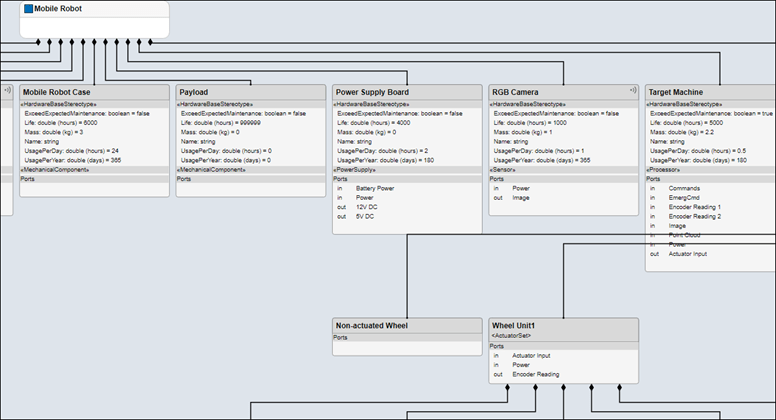
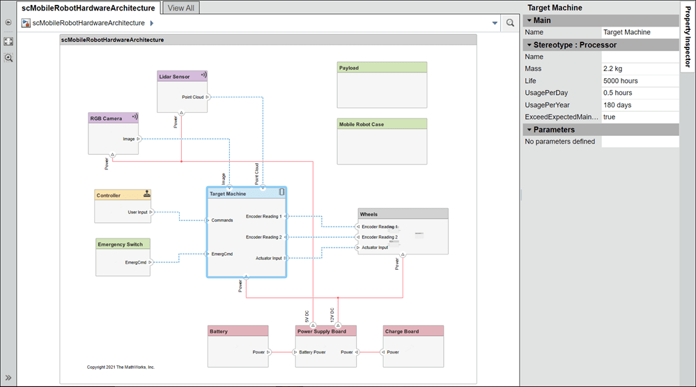
The hardware architecture model describes the hardware components and their connections: the sensor, actuators, and embedded processor. The colors and icons indicate the stereotypes used for each element. To open the hardware architecture model, double-click the file or run this command.
systemcomposer.openModel("scMobileRobotHardwareArchitecture");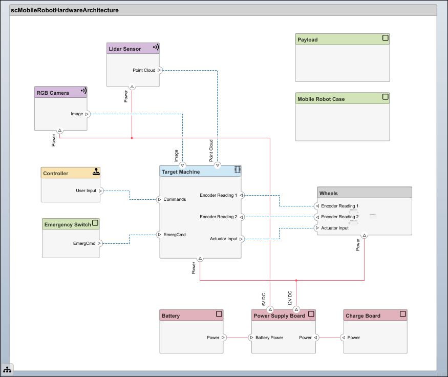
View Stereotypes and Properties in Profile Editor
In this example, the HardwareBaseStereotype stereotype is defined as an abstract stereotype and is extended to connector and component stereotypes. For example, a DataConnector stereotype is a connector stereotype that inherits the HardwareBaseStereotype.
To focus on expected time before first maintenance, define properties such as UsagePerDay, UsagePerYear, and Life. Setting these properties allows you to analyze each hardware component to make sure the mobile robot will last until first expected year of maintenance. To open the Profile Editor, navigate to Modeling > Profile Editor.
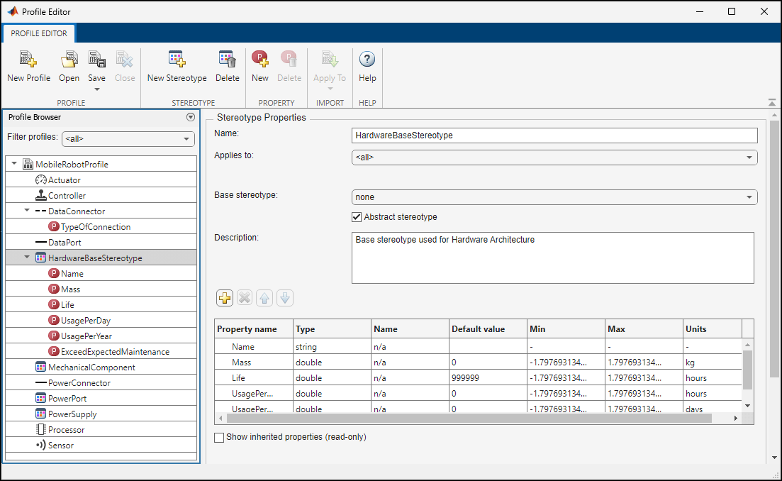
In addition to properties like name and mass, the DataConnector stereotype has a property of enumeration type, TypeOfConnection, that describes which of the three connection types it uses: RS232, Ethernet, or USB. To generate custom data types, create a script similar to ConnectorType.m. For more information, see Simulink Enumerations.
Apply Stereotypes to Elements in Model
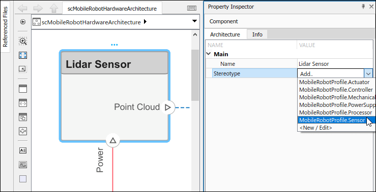
Once you define stereotypes in the Profile Editor, you can apply them to components, ports, and connectors. Apply stereotypes using the Property Inspector. To open the Property Inspector, navigate to Modeling > Property Inspector.
To add stereotypes to elements, select the element in the diagram. In the Property Inspector, select Main > Stereotype. You can apply multiple stereotypes to the same element. Apply the MobileRobotProfile.Sensor stereotype to the Lidar Sensor component to add properties.
Some components remain in use for longer periods of time than others. The Lidar Sensor component is used for obstacle avoidance in this scenario, so it is always in use except when it is charging. The RGB Camera only aligns the robot to the charging station, so it is in use for a shorter period per day. You can change values for the UsagePerDay, UsagePerYear, and Life properties to determine the expected maintenance time for components that are each used with different frequency.
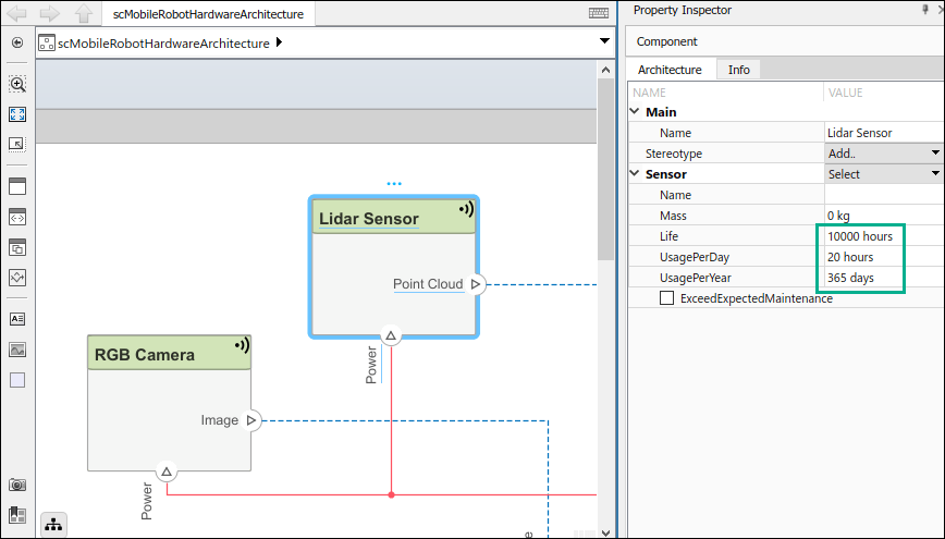
The property ExceedExpectedMaintenance is set to false by default. This property will update when you run your analysis.
Architecture Views for Hardware Architecture Model
Use the Architecture Views Gallery to review changes you make in the architecture model. Architecture views allow you to create filtered views and thereby focus on few elements of the model, which enables you to navigate a complex model more easily.
To open the Architecture Views Gallery, navigate to Modeling > Architecture Views.
Select New > View to create a new view.
Name the view in the View Properties pane on the right.
In the bottom pane, under View Configurations > Filter, select from the list Add Component Filter > Select All Components to show all components in the view. Select Apply
 .
.Select the Component Hierarchy view. The hierarchy of the components is flattened to show all subcomponents in one view.
You can apply a filter to view components with the Life Expectancy requirement. Select New > View and name the view in the View Properties pane on the right.
In the bottom pane under View Configurations > Filter, select Add Component Filter.
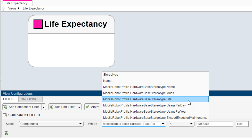
Select Apply
 . Observe the components with the
 Lifeproperty defined.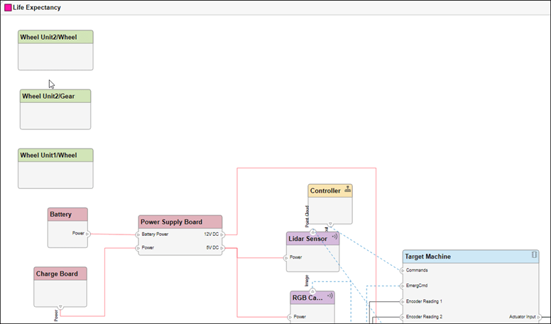
The components with the Life property defined are components for which expected time before first maintenance is a concern.
Analyze Hardware Components for Life Expectancy
Analyze the system to check if the components and connectors will last longer than the expected time before first maintenance. This value is set to two years in the analysis function. Navigate to Modeling > Analysis Model to open the Instantiate Architecture Model tool.
Select all stereotypes to make them available on the instance model. Select scMobileRobotAnalysis.m as the analysis function. The iteration order determines in what order the component hierarchy is analyzed. However, since each component is analyzed separately, the order does not matter. Select the default iteration order Pre-order.
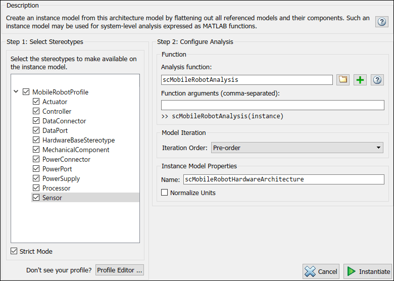
Click Instantiate to instantiate the model and open the Analysis Viewer tool. Relevant components and connectors with stereotypes are shown. Since all stereotypes are selected, all elements with stereotypes are shown in the instance model. Model analysis will calculate which components and connectors will last longer than the expected two years. Click Analyze to perform the calculation.
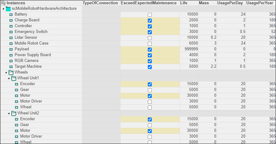
The components for which usage is not defined are components that last significantly longer than the expected time and are therefore excluded from analysis. The analysis function calculates whether the time before first maintenance for each component and connector will exceed Life, which is set to two years. The unchecked boxes indicate that components and connectors will need maintenance within two years.
To refresh the instance model in the Analysis Viewer, select Overwrite, then click Refresh. This action will retrieve the values back from the source model, in this case, the hardware architecture model. Since ExceedExpectedMaintenance was the only property changed, it reverts back to its default value. Conversely, when you click Update the property values in the hardware architecture source update according to the instance model.
Use Web View to Export Architecture Model
Web views are dynamic view-only HTML versions of a model. For an architecture model, web views allow you to visualize port interfaces, element stereotypes and properties, and parameters on components. In this example, you can interact with stereotypes and properties for the scMobileRobotHardwareArchitecture model. For more information on web views, see Web Views (Simulink Report Generator). A Simulink® Report Generator™ license is required to export architecture models to web views.
Follow the instructions in Export Models to Web View Files (Simulink Report Generator) to export the architecture model into a web view. To display your web view on your browser, follow the instructions in Display and Navigate Through Web Views (Simulink Report Generator).
References
[1] Rahman, Mohd Azizi Abdul, Katsuhiro Mayama, Takahiro Takasu, Akira Yasuda, and Makoto Mizukawa. “Model-Driven Development of Intelligent Mobile Robot Using Systems Modeling Language (SysML).” In Mobile Robots: Control Architectures, Bio-Interfacing, Navigation, Multi Robot Motion Planning and Operator Training, edited by Janusz Będkowski. InTech Open, 2011. https://doi.org/10.5772/26906.
See Also
applyProfile | applyStereotype | openViews | instantiate