dsp.FIRHalfbandInterpolator
Interpolate signal using polyphase FIR halfband filter
Description
The dsp.FIRHalfbandInterpolator
System object™ performs efficient polyphase interpolation of the input signal using an
upsampling factor of two. You can use dsp.FIRHalfbandInterpolator to
implement the synthesis portion of a two-band filter bank to synthesize a signal from
lowpass and highpass subbands. dsp.FIRHalfbandInterpolator uses an FIR
equiripple design or a Kaiser window design to construct the halfband filters and a
polyphase implementation to filter the input. For more details, see Algorithms.
To upsample and interpolate your data:
Create the
dsp.FIRHalfbandInterpolatorobject and set its properties.Call the object with arguments, as if it were a function.
To learn more about how System objects work, see What Are System Objects?
This object supports C/C++ code generation and SIMD code generation under certain conditions. This object also supports code generation for ARM® Cortex®-M and ARM Cortex-A processors. For more information, see Code Generation.
Creation
Syntax
Description
firhalfbandinterp = dsp.FIRHalfbandInterpolatorfirhalfbandinterp, with the default settings. Under the
default settings, the System object upsamples and interpolates the input data using a halfband
frequency of 11025 Hz, a transition width of
4.1 kHz, and a stopband attenuation of
80 dB. The design method is set to
"Auto".
firhalfbandinterp = dsp.FIRHalfbandInterpolator(PropertyName=Value)
Example:
firhalfbandinterp =
                        dsp.FIRHalfbandInterpolator(Specification="Filter order
                        and stopband attenuation")
creates an FIR
halfband interpolator object with filter order set to 52 and
stopband attenuation set to 80 dB.
.
Properties
Usage
Description
y = firhalfbandinterp(x1,x2)x1 and x2. x1
is the lowpass output of a halfband analysis filter bank and
x2 is the highpass output of a halfband analysis filter
bank. dsp.FIRHalfbandInterpolator implements a synthesis filter
bank only when the FilterBankInputPort property is set to
true.
Input Arguments
Output Arguments
Object Functions
To use an object function, specify the
System object as the first input argument. For
example, to release system resources of a System object named obj, use
this syntax:
release(obj)
Examples
Create two lowpass halfband interpolation filters. The design method in the first filter is set to "Equiripple" and in the second filter is set to "Kaiser".
Specify a filter order of 52 and a transition width of 0.0930 in normalized frequency units.
Order = 52;
TW = 0.0930;
filterspec = "Filter order and transition width";

firhalfbandinterpEqui = dsp.FIRHalfbandInterpolator(...
    NormalizedFrequency=true,...
    Specification=filterspec,...
    FilterOrder=Order,...
    TransitionWidth=0.0930,...
    DesignMethod="Equiripple");

firhalfbandinterpKaiser = dsp.FIRHalfbandInterpolator(...
    NormalizedFrequency=true,...
    Specification=filterspec,...
    FilterOrder=Order,...
    TransitionWidth=TW,...
    DesignMethod="Kaiser");
Plot the impulse response of both the filters. The zeroth-order coefficient is delayed by 26 samples, which is equal to the group delay of the filter. This yields a causal halfband filter.
hfvt = filterAnalyzer(firhalfbandinterpEqui,firhalfbandinterpKaiser,...
    Analysis="impulse");
setLegendStrings(hfvt,["Equiripple","Kaiser"])

Plot the magnitude and phase response.
If the filter specifications are tight, say a very high filter order with a very narrow transition width, the filter designed using the "Kaiser" method converges more effectively.
hvftMag = filterAnalyzer(firhalfbandinterpEqui,firhalfbandinterpKaiser,...
    Analysis="magnitude");
setLegendStrings(hvftMag,["Equiripple","Kaiser"])

hvftPhase = filterAnalyzer(firhalfbandinterpEqui,firhalfbandinterpKaiser,...
    Analysis="phase");
setLegendStrings(hvftPhase,["Equiripple","Kaiser"])

Design an equiripple FIR halfband interpolator object of order 48 using the designHalfbandFIR function. Set the Verbose argument to true.
hbFIR = designHalfbandFIR(FilterOrder=48,SystemObject=true,...
    Structure="interp",Verbose=true)
designHalfbandFIR(FilterOrder=48, TransitionWidth=0.1, DesignMethod="equiripple", Passband="lowpass", Structure="interp", InputSampleRate="normalized", PhaseConstraint="linear", Datatype="double", SystemObject=true)
hbFIR =
  dsp.FIRHalfbandInterpolator with properties:

          Specification: 'Coefficients'
              Numerator: [0 -0.0082 0 0.0079 0 -0.0116 0 0.0165 0 -0.0227 0 0.0309 0 -0.0419 0 0.0571 0 -0.0800 0 0.1193 0 -0.2073 0 0.6350 1 0.6350 0 -0.2073 0 0.1193 0 -0.0800 0 0.0571 0 -0.0419 0 0.0309 0 -0.0227 0 0.0165 0 -0.0116 0 … ] (1×49 double)
    FilterBankInputPort: false

  Show all properties
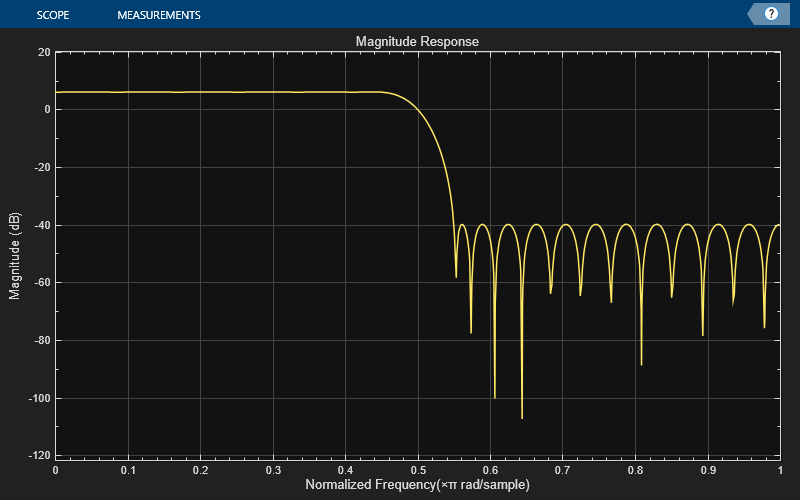
Create a dsp.DynamicFilterVisualizer object and visualize the magnitude response of the filter.
dfv = dsp.DynamicFilterVisualizer(NormalizedFrequency=true);
dfv(hbFIR);
The input is a cosine wave with an angular frequency of radians/sample.
input = cos(pi/4*(0:39)');
Interpolate the cosine signal using the FIR halfband interpolator.
output = hbFIR(input);
Plot the original and interpolated signals. In order to plot the two signals on the same plot, you must account for the output delay introduced by the FIR halfband interpolator and the scaling introduced by the filter. Use the outputDelay function to compute the delay value introduced by the interpolator. Shift the output by this delay value.
Visualize the input and the resampled signals. The input and output values coincide every other sample due to the interpolation factor of 2.
[delay,FsOut] = outputDelay(hbFIR,FsIn=1)
delay =
12
FsOut =
2
nInput = (0:length(input)-1);
tOutput = (0:length(output)-1)/FsOut-delay;
stem(tOutput,output,"filled",MarkerSize=4); hold on;
stem(nInput,input); hold off;
xlim([-5,20])
legend("Interpolated by 2","Input signal",Location="best");

Use a halfband analysis filter bank and interpolation filter to extract the low frequency subband from a speech signal.
Note: The audioDeviceWriter System object™ is not supported in MATLAB Online.
Set up the audio file reader, the analysis filter bank, audio device writer, and interpolation filter. The sample rate of the audio data is 22050 Hz. The order of the halfband filter is 52, with a transition width of 2 kHz.
Set the design method to "Auto". This mode chooses one of the filter design methods, equiripple or Kaiser, based on the design parameters of the filter.
afr = dsp.AudioFileReader(...
    "speech_dft.mp3",...
    SamplesPerFrame=1024);

filtSpec = "Filter order and transition width";
Order = 52;
TW = 2000;

firhalfbanddecim = dsp.FIRHalfbandDecimator(...
    Specification=filtSpec,...
    FilterOrder=Order,...
    TransitionWidth=TW,...
    DesignMethod="Auto",...
    SampleRate=afr.SampleRate);

firhalfbandinterp = dsp.FIRHalfbandInterpolator(...
    Specification=filtSpec,...
    FilterOrder=Order,...
    TransitionWidth=TW,...
    DesignMethod="Auto",...
    SampleRate=afr.SampleRate/2);

adw = audioDeviceWriter(SampleRate=afr.SampleRate);
View the magnitude response of the halfband filter.
filterAnalyzer(firhalfbanddecim)

Read the speech signal from the audio file in frames of 1024 samples. Filter the speech signal into lowpass and highpass subbands with a halfband frequency of 5512.5 Hz. Reconstruct a lowpass approximation of the speech signal by interpolating the lowpass subband. Play the filtered output.
while ~isDone(afr)
  audioframe = afr();
  xlo = firhalfbanddecim(audioframe);
  ylow = firhalfbandinterp(xlo);
  adw(ylow);
end
Wait until the audio file is played to the end, then close the input file and release the audio output resource.
release(afr);
release(adw);
Use a halfband decimator and interpolator to implement a two-channel filter bank. This example uses an audio file input and shows that the power spectrum of the filter bank output does not differ significantly from the input.
Note: The audioDeviceWriter System object™ is not supported in MATLAB Online.
Set up the audio file reader and device writer. Construct the FIR halfband decimator and interpolator. Finally, set up the spectrum analyzer to display the power spectra of the filter-bank input and output.
AF = dsp.AudioFileReader("speech_dft.mp3",SamplesPerFrame=1024);
AP = audioDeviceWriter(SampleRate=AF.SampleRate);

filterspec = "Filter order and transition width";
Order = 52;
TW = 2000;

firhalfbanddecim = dsp.FIRHalfbandDecimator(...
    Specification=filterspec,FilterOrder=Order,...
    TransitionWidth=TW,DesignMethod="Auto",...
    SampleRate=AF.SampleRate);

firhalfbandinterp = dsp.FIRHalfbandInterpolator(...
    Specification=filterspec,FilterOrder=Order,...
    TransitionWidth=TW,SampleRate=AF.SampleRate/2,...
    DesignMethod="Auto",...
    FilterBankInputPort=true);

SpecAna = spectrumAnalyzer(SampleRate=AF.SampleRate,...
    PlotAsTwoSidedSpectrum=false,...
    ShowLegend=true,...
    ChannelNames={"Input signal","Filtered output signal"});
Read the audio 1024 samples at a time. Filter the input to obtain the lowpass and highpass subband signals decimated by a factor of two. This is the analysis filter bank. Use the halfband interpolator as the synthesis filter bank. Display the running power spectrum of the audio input and the output of the synthesis filter bank. Play the output.
while ~isDone(AF)
    audioInput = AF();
    [xlo,xhigh] = firhalfbanddecim(audioInput);
    audioOutput = firhalfbandinterp(xlo,xhigh);
    spectrumInput = [audioInput audioOutput];
    SpecAna(spectrumInput);
    AP(audioOutput);
end

release(AF);
release(AP);
release(SpecAna);

Create a half-band interpolation filter. The filter order is 52 with a transition width of 0.0930 in normalized frequency units. Use the filter to upsample and interpolate a multichannel input.
Set the design method to "Auto". This mode chooses one of the filter design methods, equiripple or Kaiser, based on the specified filter design parameters.
Fs = 44.1e3;
filterspec = "Filter order and transition width";
Order = 52;
TW = 0.0930;
firhalfbandinterp = dsp.FIRHalfbandInterpolator(...
    NormalizedFrequency=true,...
    Specification=filterspec,...
    FilterOrder=Order,...
    TransitionWidth=TW,...
    DesignMethod="Auto");
x = randn(1024,4);
y = firhalfbandinterp(x);
More About
Algorithms
The FIR halfband interpolator uses an efficient polyphase implementation for halfband filters when you filter the input signal. You can use a polyphase implementation to move the upsampling operation after filtering. This allows you to filter at the lower sampling rate.
Splitting a filter’s impulse response h(n) into two polyphase components results in an even polyphase component with z-transform of
and an odd polyphase component with z-transform of
The z-transform of the filter can be written in terms of the even and odd polyphase components as
You can represent the upsampling by 2 and then filtering the signal using this figure.

Using the multirate noble identity for upsampling, you can move the upsampling operation after the filtering. This enables you to filter at the lower rate.

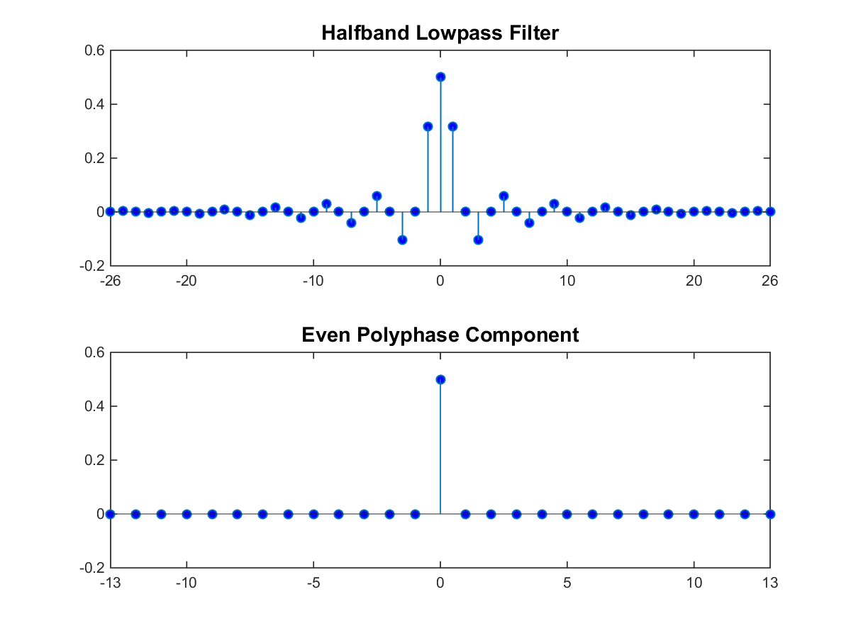
For a halfband filter, the only nonzero coefficient in the even polyphase component is the coefficient corresponding to z0. Implementing the halfband filter as a causal FIR filter shifts the nonzero coefficient to approximately z-N/4, where N is the number of filter taps. This process is shown in the following figure. The top plot shows a halfband filter of order 52. The bottom plot shows the even polyphase component. Both filters are noncausal. Delaying the even polyphase component by 13 samples creates a causal FIR filter.
To efficiently implement the halfband interpolator, the algorithm replaces the upsampling operator, delay block, and adder with a commutator switch. The commutator switch starts on the even branch and takes input samples from the two branches alternately, one sample at a time. This doubles the sampling rate of the input signal. Which polyphase component reduces to a simple delay depends on whether the half order of the filter is even or odd.
Here is the implementation when the filter half order is even. In this diagram, H0(z) becomes the gain followed by the delay.

When the filter half order is odd, H1(z) becomes the gain followed by the delay and the switch. This is because the delay required to make the even polyphase component causal can be odd or even depending on the filter half order.
To confirm this behavior, run the following code in the MATLAB® command prompt and inspect the polyphase components of the following filters.
filterspec = "Filter order and stopband attenuation";
halfOrderEven = dsp.FIRHalfbandInterpolator(Specification=filterspec,...
    FilterOrder=64,StopbandAttenuation=80);
halfOrderOdd = dsp.FIRHalfbandInterpolator(Specification=filterspec,...
    FilterOrder=54,StopbandAttenuation=80);
polyphase(halfOrderEven)
polyphase(halfOrderOdd)
One of the polyphase components has a single nonzero coefficient indicating that it is a simple delay. To preserve the output power of the signal, the coefficients are scaled by the interpolation factor, two. To see this scaling, compare the polyphase components of a halfband interpolator with the coefficients of a halfband decimator.
hfirinterp = dsp.FIRHalfbandInterpolator;
hfirdecim = dsp.FIRHalfbandDecimator;
polyphase(hfirdecim)
polyphase(hfirinterp)
Synthesis Filter Bank
The FIR halfband interpolator implements the synthesis portion of a two-band filter bank to synthesize a signal from lowpass and highpass subbands.

For more information on filter banks, see Overview of Filter Banks.
To summarize, the FIR halfband interpolator:
Filters the input before upsampling with the even and odd polyphase components of the filter.
Exploits the fact that one filter polyphase component is a simple delay for a halfband filter.
Acts as a synthesis filter bank.
References
[1] Harris, F.J. Multirate Signal Processing for Communication Systems, Prentice Hall, 2004, pp. 208–209.
Extended Capabilities
Version History
Introduced in R2014bSee Also
Functions
designHalfbandFIR|freqz|freqzmr|filterAnalyzer|info|cost|coeffs|polyphase|outputDelay|setInputSampleRate
Objects
dsp.FIRHalfbandDecimator|dsp.IIRHalfbandInterpolator|dsp.DyadicSynthesisFilterBank|dsp.ChannelSynthesizer