Main Content

radarDetectionGenerator

Generate radar detections for driving scenario

radarDetectionGenerator is not recommended unless you require C/C++ code generation. Use drivingRadarDataGenerator instead. For more information, see Compatibility Considerations.

Description

The radarDetectionGenerator System object™ generates detections from a radar sensor mounted on an ego vehicle. All detections are referenced to the coordinate system of the ego vehicle. You can use the radarDetectionGenerator object in a scenario containing actors and trajectories, which you can create by using a drivingScenario object. The object can simulate real detections with added random noise and also generate false alarm detections. In addition, you can use the radarDetectionGenerator object to create input to a multiObjectTracker. When building scenarios using the Driving Scenario Designer app, the radar sensors mounted on the ego vehicle are output as radarDetectionGenerator objects.

To generate radar detections:

  1. Create the radarDetectionGenerator object and set its properties.

  2. Call the object with arguments, as if it were a function.

To learn more about how System objects work, see What Are System Objects?

Creation

Description

sensor = radarDetectionGenerator creates a radar detection generator object with default property values.

example

sensor = radarDetectionGenerator(Name,Value) sets properties using one or more name-value pairs. For example, radarDetectionGenerator('DetectionCoordinates','Sensor Cartesian','MaxRange',200) creates a radar detection generator that reports detections in the sensor Cartesian coordinate system and has a maximum detection range of 200 meters. Enclose each property name in quotes.

Properties

expand all

Unless otherwise indicated, properties are nontunable, which means you cannot change their values after calling the object. Objects lock when you call them, and the release function unlocks them.

If a property is tunable, you can change its value at any time.

For more information on changing property values, see System Design in MATLAB Using System Objects.

Unique sensor identifier, specified as a positive integer. This property distinguishes detections that come from different sensors in a multisensor system.

Example: 5

Data Types: double

Required time interval between sensor updates, specified as a positive real scalar. The drivingScenario object calls the radar detection generator at regular time intervals. The radar detector generates new detections at intervals defined by the UpdateInterval property. The value of the UpdateInterval property must be an integer multiple of the simulation time interval. Updates requested from the sensor between update intervals contain no detections. Units are in seconds.

Example: 5

Data Types: double

Location of the radar sensor center, specified as an [x y] vector. The SensorLocation and Height properties define the coordinates of the radar sensor with respect to the ego vehicle coordinate system. The default value corresponds to a radar mounted at the center of the front grill of a sedan. Units are in meters.

Example: [4 0.1]

Data Types: double

Radar sensor height above the ground plane, specified as a positive real scalar. The height is defined with respect to the vehicle ground plane. The SensorLocation and Height properties define the coordinates of the radar sensor with respect to the ego vehicle coordinate system. The default value corresponds to a radar mounted at the center of the front grill of a sedan. Units are in meters.

Example: 0.3

Data Types: double

Yaw angle of radar sensor, specified as a real scalar. The yaw angle is the angle between the center line of the ego vehicle and the downrange axis of the radar sensor. A positive yaw angle corresponds to a clockwise rotation when looking in the positive direction of the z-axis of the ego vehicle coordinate system. Units are in degrees.

Example: -4

Data Types: double

Pitch angle of sensor, specified as a real scalar. The pitch angle is the angle between the downrange axis of the radar sensor and the x-y plane of the ego vehicle coordinate system. A positive pitch angle corresponds to a clockwise rotation when looking in the positive direction of the y-axis of the ego vehicle coordinate system. Units are in degrees.

Example: 3

Data Types: double

Roll angle of the radar sensor, specified as a real scalar. The roll angle is the angle of rotation of the downrange axis of the radar around the x-axis of the ego vehicle coordinate system. A positive roll angle corresponds to a clockwise rotation when looking in the positive direction of the x-axis of the coordinate system. Units are in degrees.

Example: -4

Data Types: double

Azimuth and elevation fields of view of radar sensor, specified as a real-valued 1-by-2 vector of positive values, [azfov elfov]. The field of view defines the angular extent spanned by the sensor. Each component must lie in the interval (0,180]. Targets outside of the field of view of the radar are not detected. Units are in degrees.

Example: [14 7]

Data Types: double

Maximum detection range, specified as a positive real scalar. The radar cannot detect a target beyond this range. Units are in meters.

Example: 200

Data Types: double

Minimum and maximum detection range rates, specified as a real-valued 1-by-2 vector. The radar cannot detect a target out this range rate interval. Units are in meters per second.

Example: [-20 100]

Dependencies

To enable this property, set the HasRangeRate property to true.

Data Types: double

Probability of detecting a target, specified as a positive real scalar less than or equal to one. This quantity defines the probability of detecting target that has a radar cross-section, ReferenceRCS, at the reference detection range, ReferenceRange.

False alarm rate within a radar resolution cell, specified as a positive real scalar in the range [10–7,10–3]. Units are dimensionless.

Example: 1e-5

Data Types: double

Reference range for a given probability of detection, specified as a positive real scalar. The reference range is the range when a target having a radar cross-section specified by ReferenceRCS is detected with a probability of specified by DetectionProbability. Units are in meters.

Data Types: double

Reference radar cross-section (RCS) for given probability of detection, specified as a nonnegative real scalar. The reference RCS is the value at which a target is detected with probability specified by DetectionProbability. Units are in dBsm.

Data Types: double

This property is read-only.

Radar loop gain, specified as a real scalar. Radar loop gain is related to the reported signal-to-noise ratio of the radar, SNR, the target radar cross section, RCS, and target range, R by

SNR = RadarLoopGain + RCS - 40*log10(R)

SNR and RCS units are in dB and dBsm, respectively and range units are in meters. RadarLoopGain depends on the DetectionProbability, ReferenceRange, ReferenceRCS, and FalseAlarmRate property values. Units are in dB.

Data Types: double

Azimuth resolution of the radar, specified as a positive real scalar. The azimuth resolution defines the minimum separation in azimuth angle at which the radar can distinguish two targets. The azimuth resolution is typically the 3dB-downpoint in azimuth angle beamwidth of the radar. Units are in degrees.

Data Types: double

Elevation resolution of the radar, specified as a positive real scalar. The elevation resolution defines the minimum separation in elevation angle at which the radar can distinguish two targets. The elevation resolution is typically the 3dB-downpoint in elevation angle beamwidth of the radar. Units are in degrees.

Dependencies

To enable this property, set the HasElevation property to true.

Data Types: double

Range resolution of the radar, specified as a positive real scalar. The range resolution defines the minimum separation in range at which the radar can distinguish between two targets. Units are in meters.

Data Types: double

Range rate resolution of the radar, specified as a positive real scalar. The range rate resolution defines the minimum separation in range rate at which the radar can distinguish between two targets. Units are in meters per second.

Dependencies

To enable this property, set the HasRangeRate property to true.

Data Types: double

Azimuth bias fraction of the radar, specified as a nonnegative real scalar. The azimuth bias is expressed as a fraction of the azimuth resolution specified in AzimuthResolution. Units are dimensionless.

Data Types: double

Elevation bias fraction of the radar, specified as a nonnegative real scalar. Elevation bias is expressed as a fraction of the elevation resolution specified in ElevationResolution. Units are dimensionless.

Dependencies

To enable this property, set the HasElevation property to true.

Data Types: double

Range bias fraction of the radar, specified as a nonnegative real scalar. Range bias is expressed as a fraction of the range resolution specified in RangeResolution. Units are dimensionless.

Data Types: double

Range rate bias fraction of the radar, specified as a nonnegative real scalar. Range rate bias is expressed as a fraction of the range rate resolution specified in RangeRateResolution. Units are dimensionless.

Dependencies

To enable this property, set the HasRangeRate property to true.

Data Types: double

Enable the radar to measure target elevation angles, specified as false or true. Set this property to true to model a radar sensor that can estimate target elevation. Set this property to false to model a radar sensor that cannot measure elevation.

Data Types: logical

Enable the radar to measure target range rates, specified as false or true. Set this property to true to model a radar sensor which can estimate target range rate. Set this property to false to model a radar sensor that cannot measure range rate.

Data Types: logical

Enable adding noise to radar sensor measurements, specified as true or false. Set this property to true to add noise to the radar measurements. Otherwise, the measurements have no noise. Even if you set HasNoise to false, the object still computes the MeasurementNoise property of each detection.

Data Types: logical

Enable reporting false alarm radar measurements, specified as true or false. Set this property to true to report false alarms. Otherwise, only actual detections are reported.

Data Types: logical

Enable line-of-sight occlusion, specified as true or false. To generate detections only from objects for which the radar has a direct line of sight, set this property to true. For example, with this property enabled, the radar does not generate a detection for a vehicle that is behind another vehicle and blocked from view.

Data Types: logical

Source of maximum number of detections reported by the sensor, specified as 'Auto' or 'Property'. When this property is set to 'Auto', the sensor reports all detections. When this property is set to 'Property', the sensor reports no more than the number of detections specified by the MaxNumDetections property.

Data Types: char | string

Maximum number of detections reported by the sensor, specified as a positive integer. Detections are reported in order of distance to the sensor until the maximum number is reached.

Dependencies

To enable this property, set the MaxNumDetectionsSource property to 'Property'.

Data Types: double

Coordinate system of reported detections, specified as one of these values:

  • 'Ego Cartesian' — Detections are reported in the ego vehicle Cartesian coordinate system.

  • 'Sensor Cartesian' — Detections are reported in the sensor Cartesian coordinate system.

  • 'Sensor Spherical' — Detections are reported in a spherical coordinate system. This coordinate system is centered at the radar and aligned with the orientation of the radar on the ego vehicle.

Data Types: char | string

Actor profiles, specified as a structure or as an array of structures. Each structure contains the physical and radar characteristics of an actor.

  • If ActorProfiles is a single structure, all actors passed into the radarDetectionGenerator object use this profile.

  • If ActorProfiles is an array, each actor passed into the object must have a unique actor profile.

To generate an array of structures for your driving scenario, use the actorProfiles function. The table shows the valid structure fields. If you do not specify a field, that field is set to its default value. If no actors are passed into the object, then the ActorID field is not included.

FieldDescription
ActorIDScenario-defined actor identifier, specified as a positive integer.
ClassIDClassification identifier, specified as a nonnegative integer. 0 is reserved for an object of an unknown or unassigned class.
LengthLength of actor, specified as a positive real scalar. The default is 4.7. Units are in meters.
WidthWidth of actor, specified as a positive real scalar. The default is 1.8. Units are in meters.
HeightHeight of actor, specified as a positive real scalar. The default is 1.4. Units are in meters.
OriginOffset

Offset of the rotational center of the actor from its geometric center, specified as an [x y z] real-valued vector. The rotational center, or origin, is located at the bottom center of the actor. For vehicles, the rotational center is the point on the ground beneath the center of the rear axle. The default is [0 0 0]. Units are in meters.

RCSPatternRadar cross-section pattern of actor, specified as a numel(RCSElevationAngles)-by-numel(RCSAzimuthAngles) real-valued matrix. The default is [10 10; 10 10]. Units are in decibels per square meter.
RCSAzimuthAnglesAzimuth angles corresponding to rows of RCSPattern, specified as a vector of real values in the range [–180, 180]. The default is [-180 180]. Units are in degrees.
RCSElevationAnglesElevation angles corresponding to rows of RCSPattern, specified as a vector of real values in the range [–90, 90]. The default is [-90 90]. Units are in degrees.

For full definitions of the structure fields, see the actor and vehicle functions.

Usage

Description

example

dets = sensor(actors,time) creates radar detections, dets, from sensor measurements taken of actors at the current simulation time. The object can generate sensor detections for multiple actors simultaneously. Do not include the ego vehicle as one of the actors.

[dets,numValidDets] = sensor(actors,time) also returns the number of valid detections reported, numValidDets.

[dets,numValidDets,isValidTime] = sensor(actors,time) also returns a logical value, isValidTime, indicating that the UpdateInterval time has elapsed.

Input Arguments

expand all

Scenario actor poses, specified as a structure or structure array. Each structure corresponds to an actor. You can generate these structures using the actorPoses function. You can also create these structures manually.

FieldDescription
ActorID

Scenario-defined actor identifier, specified as a positive integer.

Position

Position of actor, specified as a real-valued vector of the form [x y z]. Units are in meters.

Velocity

Velocity (v) of actor in the x- y-, and z-directions, specified as a real-valued vector of the form [vx vy vz]. Units are in meters per second.

Roll

Roll angle of actor, specified as a real-valued scalar. Units are in degrees.

Pitch

Pitch angle of actor, specified as a real-valued scalar. Units are in degrees.

Yaw

Yaw angle of actor, specified as a real-valued scalar. Units are in degrees.

AngularVelocity

Angular velocity (ω) of actor in the x-, y-, and z-directions, specified as a real-valued vector of the form [ωx ωy ωz]. Units are in degrees per second.

For full definitions of the structure fields, see the actor and vehicle functions.

Current simulation time, specified as a nonnegative real scalar. The drivingScenario object calls the radar detection generator at regular time intervals. The radar detector generates new detections at intervals defined by the UpdateInterval property. The value of the UpdateInterval property must be an integer multiple of the simulation time interval. Updates requested from the sensor between update intervals contain no detections. Units are in seconds.

Example: 10.5

Data Types: double

Output Arguments

expand all

Radar sensor detections, returned as a cell array of objectDetection objects. Each object contains these fields:

PropertyDefinition
TimeMeasurement time
MeasurementObject measurements
MeasurementNoiseMeasurement noise covariance matrix
SensorIndexUnique ID of the sensor
ObjectClassIDObject classification
MeasurementParametersParameters used by initialization functions of nonlinear Kalman tracking filters
ObjectAttributesAdditional information passed to tracker

For Cartesian coordinates, Measurement, MeasurementNoise, and MeasurementParameters are reported in the coordinate system specified by the DetectionCoordinates property of the radarDetectionGenerator.

For spherical coordinates, Measurement and MeasurementNoise are reported in the spherical coordinate system based on the sensor Cartesian coordinate system. MeasurementParameters are reported in sensor Cartesian coordinates.

Measurement

DetectionCoordinates PropertyMeasurement and Measurement Noise Coordinates
'Ego Cartesian'

Coordinate Dependence on HasRangeRate

HasRangeRateCoordinates
true[x;y;z;vx;vy;vz]
false[x;y;z]
'Sensor Cartesian'
'Sensor Spherical'

Coordinate Dependence on HasRangeRate and HasElevation

HasRangeRateHasElevationCoordinates
truetrue[az;el;rng;rr]
truefalse[az;rng;rr]
falsetrue[az;el;rng]
falsefalse[az;rng]

MeasurementParameters

ParameterDefinition
Frame Enumerated type indicating the frame used to report measurements. When Frame is set to 'rectangular', detections are reported in Cartesian coordinates. When Frame is set 'spherical', detections are reported in spherical coordinates.
OriginPosition3-D vector offset of the sensor origin from the ego vehicle origin. The vector is derived from the SensorLocation and Height properties specified in the radarDetectionGenerator.
OrientationOrientation of the vision sensor coordinate system with respect to the ego vehicle coordinate system. The orientation is derived from the Yaw, Pitch, and Roll properties of the radarDetectionGenerator.
HasVelocityIndicates whether measurements contain velocity or range rate components.
HasElevationIndicates whether measurements contain elevation components.

ObjectAttributes

AttributeDefinition
TargetIndexIdentifier of the actor, ActorID, that generated the detection. For false alarms, this value is negative.
SNRDetection signal-to-noise ratio in dB.

Number of detections, returned as a nonnegative integer.

  • When the MaxNumDetectionsSource property is set to 'Auto', numValidDets is set to the length of dets.

  • When the MaxNumDetectionsSource property is set to 'Property', dets is a cell array with length determined by the MaxNumDetections property. No more than MaxNumDetections number of detections are returned. If the number of detections is fewer than MaxNumDetections, the first numValidDets elements of dets hold valid detections. The remaining elements of dets are set to the default value.

Data Types: double

Valid detection time, returned as 0 or 1. isValidTime is 0 when detection updates are requested at times that are between update intervals specified by UpdateInterval.

Data Types: logical

Object Functions

To use an object function, specify the System object as the first input argument. For example, to release system resources of a System object named obj, use this syntax:

release(obj)

expand all

isLockedDetermine if System object is in use
stepRun System object algorithm
releaseRelease resources and allow changes to System object property values and input characteristics
resetReset internal states of System object

Examples

collapse all

Generate detections using a forward-facing automotive radar mounted on an ego vehicle. Assume that there are three targets:

  • Vehicle 1 is in the center lane, directly in front of the ego vehicle, and driving at the same speed.

  • Vehicle 2 is in the left lane and driving faster than the ego vehicle by 12 kilometers per hour.

  • Vehicle 3 is in the right lane and driving slower than the ego vehicle by 5 kilometers per hour.

All positions, velocities, and measurements are relative to the ego vehicle. Run the simulation for ten steps.

dt = 0.1;
pos1 = [150 0 0];
pos2 = [160 10 0];
pos3 = [130 -10 0];
vel1 = [0 0 0];
vel2 = [12*1000/3600 0 0];
vel3 = [-5*1000/3600 0 0];
car1 = struct('ActorID',1,'Position',pos1,'Velocity',vel1);
car2 = struct('ActorID',2,'Position',pos2,'Velocity',vel2);
car3 = struct('ActorID',3,'Position',pos3,'Velocity',vel3);

Create an automotive radar sensor that is offset from the ego vehicle. By default, the sensor location is at (3.4,0) meters from the vehicle center and 0.2 meters above the ground plane. Turn off the range rate computation so that the radar sensor measures position only.

radar = radarDetectionGenerator('DetectionCoordinates','Sensor Cartesian', ...
    'MaxRange',200,'RangeResolution',10,'AzimuthResolution',10, ...
    'FieldOfView',[40 15],'UpdateInterval',dt,'HasRangeRate',false);
tracker = multiObjectTracker('FilterInitializationFcn',@initcvkf, ...
    'ConfirmationThreshold',[3 4],'DeletionThreshold',[6 6]);

Generate detections with the radar from the non-ego vehicles. The output detections form a cell array and can be passed directly in to the multiObjectTracker.

simTime = 0;
nsteps = 10;
for k = 1:nsteps
    dets = radar([car1 car2 car3],simTime);
    [confirmedTracks,tentativeTracks,allTracks] = updateTracks(tracker,dets,simTime);

Move the cars one time step and update the multi-object tracker.

    simTime = simTime + dt;
    car1.Position = car1.Position + dt*car1.Velocity;
    car2.Position = car2.Position + dt*car2.Velocity;
    car3.Position = car3.Position + dt*car3.Velocity;
end

Use birdsEyePlot to create an overhead view of the detections. Plot the sensor coverage area. Extract the X and Y positions of the targets by converting the Measurement fields of the cell array into a MATLAB® array. Display the detections on the bird's-eye plot.

BEplot = birdsEyePlot('XLim',[0 220],'YLim',[-75 75]);
caPlotter = coverageAreaPlotter(BEplot,'DisplayName','Radar coverage area');
plotCoverageArea(caPlotter,radar.SensorLocation,radar.MaxRange, ...
    radar.Yaw,radar.FieldOfView(1))
detPlotter = detectionPlotter(BEplot,'DisplayName','Radar detections');
detPos = cellfun(@(d)d.Measurement(1:2),dets,'UniformOutput',false);
detPos = cell2mat(detPos')';
if ~isempty(detPos)
    plotDetection(detPlotter,detPos)
end

Bird's-eye plot displaying radar coverage area and detections

Extended Capabilities

Version History

Introduced in R2017a

collapse all

R2021a: radarDetectionGenerator System object and Radar Detection Generator block are not recommended

The radarDetectionGenerator System object and Radar Detection Generator block are not recommended unless you require C/C++ code generation. Instead, use the drivingRadarDataGenerator System object and Driving Radar Data Generator, respectively. These new radar sensors provide additional properties for modeling radar sensors, including the ability to generate tracks and clustered detections.

There are no current plans to remove the radarDetectionGenerator System object or Radar Detection Generator block. MATLAB code and Simulink® models that use these features will continue to run. You can still import radarDetectionGenerator objects into the Driving Scenario Designer app. However, the app updates the parameters of the imported sensor to reflect the parameters of a drivingRadarDataGenerator object. In addition, when you export a scenario containing a radarDetectionGenerator sensor to MATLAB code or to a Simulink model, the app exports the sensor as a drivingRadarDataGenerator object or Driving Radar Data Generator block, respectively.

Update Code

In MATLAB code, replace all instances of radarDetectionGenerator with drivingRadarDataGenerator. In addition, update all radarDetectionGenerator properties with their equivalent drivingRadarDataGenerator properties, as shown in the table. The properties not listed in the table are either specific only to drivingRadarDataGenerator or identical in both objects.

radarDetectionGenerator PropertiesEquivalent drivingRadarDataGenerator Properties

UpdateInterval

UpdateRate

SensorLocation

Height

MountingLocation

Yaw

Pitch

Roll

MountingAngles

MaxRange

RangeLimits

MaxNumDetectionsSource

MaxNumReportsSource

MaxNumDetections

MaxNumReports

ActorProfiles

Profiles

This table shows sample code for creating a drivingRadarDataGenerator object instead of a radarDetectionGenerator object.

Discouraged UsageRecommended Replacement
    radar = radarDetectionGenerator( ...
        'SensorLocation',[-1 0], ...
        'Height',0.2, ...
        'Yaw',180, ...
        'Pitch',0, ...
        'Roll',0, ...
        'MaxRange',50);
    radar = drivingRadarDataGenerator( ...
        'MountingLocation',[-1 0 0.2], ...
        'MountingAngles',[180 0 0], ...
        'RangeLimits',[0 50]);

To generate detections from target poses at each simulation time step, replace the dets = radarDetectionGenerator(targets,time) syntax with dets = drivingRadarDataGenerator(targets,time).

Update Models

In Simulink models, replace all Radar Detection Generator blocks with Driving Radar Data Generator blocks. In the Driving Radar Data Generator blocks, update the parameter values in the same way you would update the drivingRadarDataGenerator property values described in the Update Code section.

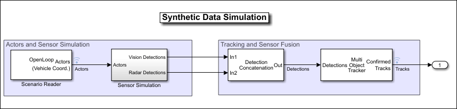
If your model contains a separate block that clusters detections, you can remove it because the Driving Radar Data Generator block clusters detections by default.

For example, in this model, the Sensor Simulation subsystem outputs concatenated detections from Radar Detection Generator blocks into a separate block that clusters the detections.

A Simulink model with radar detections being input to a detection clustering block

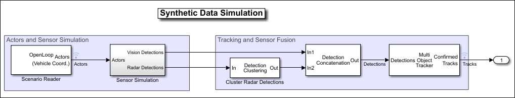
In this model, the Sensor Simulation subsystem outputs concatenated, clustered detections from Driving Radar Data Generator blocks directly into the next part of the model pipeline.

A Simulink model without the detection clustering block