深層学習を使用したビン ピッキングの 6-DoF 姿勢推定の実行
この例では、RGB-D イメージと深層学習ネットワークを使用して、ビン内の機械部品の 3 次元位置と向きを推定することにより、6 自由度 (6-DoF) の姿勢推定を実行する方法を示します。
6-DoF 姿勢は、基準フレームに対する 3 次元空間内のオブジェクトの回転と平行移動です。イメージと深度センサーを使用した 6-DoF 姿勢推定は、ロボティクスや拡張現実のためのインテリジェントなビン ピッキングなど、多くのコンピューター ビジョン システムの鍵となります。インテリジェントなビン ピッキングにおける 6-DoF 姿勢は、ある標準的な姿勢から、シーンをキャプチャするカメラによって観測された姿勢へのオブジェクトの回転と平行移動です。RGB イメージと深度測定値の両方をキャプチャする RGB-D センサーとペアになったロボット アームは、6-DoF 姿勢推定モデルを使用し、RGB-D センサーに対するオブジェクトの位置と向きを同時に検出して推定できます。推定された姿勢は、下流のタスクでオブジェクトへのパスを計画したり、特定のロボット グリッパーでオブジェクトを最も適切に掴む方法を決定したりするために使用できます。
この例では、事前学習済みの Pose Mask R-CNN ネットワークを使用して 3 つのステージで 6-DoF 姿勢推定を実行します。これは、6-DoF 姿勢推定用に設計された畳み込みニューラル ネットワークの一種です [1][2]。まず、インスタンス セグメンテーション タスクでネットワークに学習させ、境界ボックス、クラス ラベル、およびセグメンテーション マスクを予測します。次に、姿勢推定タスクでネットワークに学習させ、検出されたオブジェクトの 3 次元の回転と平行移動を予測します。初期姿勢予測を調整し、結果をグラウンド トゥルース姿勢と比較して評価するために、ネットワーク予測を可視化し、ジオメトリベースの後処理を適用します。3 つめのステージでは、この学習済みモデルに再度学習させ、回転予測を調整して精度を高めます。
この例では、Computer Vision Toolbox™ Model for Pose Mask R-CNN 6-DoF Pose Estimation が必要です。アドオン エクスプローラーから、Computer Vision Toolbox Model for Pose Mask R-CNN 6-DoF Object Pose Estimation をインストールできます。アドオンのインストールの詳細については、アドオンの取得と管理を参照してください。Computer Vision Toolbox Model for Pose Mask R-CNN 6-DoF Object Pose Estimation には、Deep Learning Toolbox™ と Image Processing Toolbox™ が必要です。
サンプル データの読み込み
サンプル RGB イメージとそれに関連する深度イメージおよびカメラの内部パラメーターをワークスペースに読み込みます。
imRGB = imread("image_00050.jpg");
load("depth_00050.mat","imDepth")
load("intrinsics_00050.mat","intrinsics")
機械部品を表すオブジェクト形状の 3 次元点群モデルをワークスペースに読み込みます。
load("pointCloudModels.mat","modelClassNames","modelPointClouds")
このオブジェクト形状の 3 次元点群モデルを可視化します。
figure
tiledlayout(2,2,'TileSpacing','Compact')
for i = 1:length(modelPointClouds)
    nexttile
    ax = pcshow(modelPointClouds(i));
    title(modelClassNames(i), Interpreter='none')
end
sgtitle("Reference Objects", Color='w');
このサンプルに関連付けられたグラウンド トゥルースの注釈 (境界ボックス、クラス、セグメンテーション マスク、および 6-DoF 姿勢) は、深層ニューラル ネットワークの学習に使用します。注釈をワークスペースに読み込みます。
load("groundTruth_00050.mat")グラウンド トゥルースの注釈と姿勢の可視化
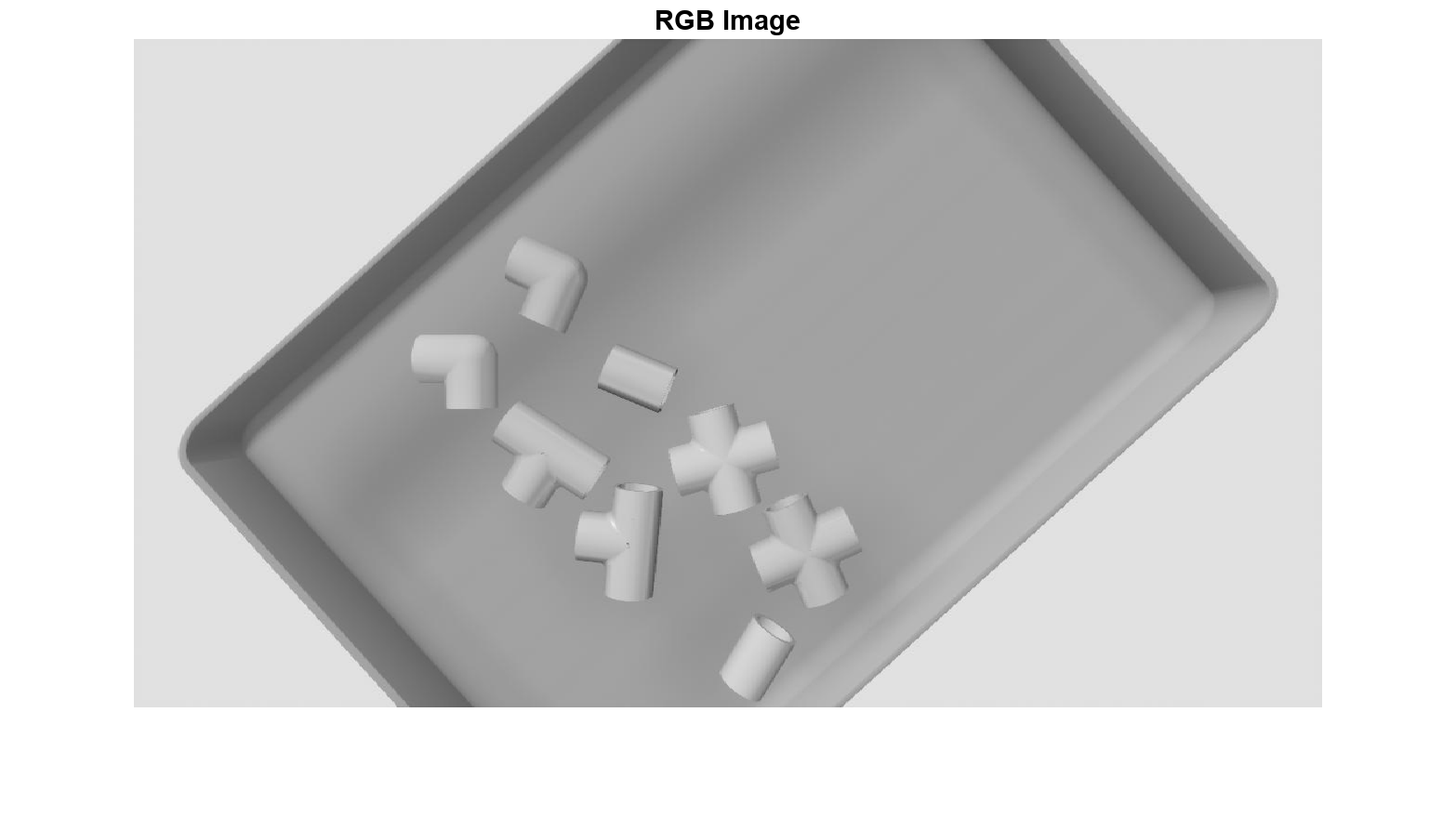
サンプルの RGB イメージを表示します。
figure
imshow(imRGB);
title("RGB Image")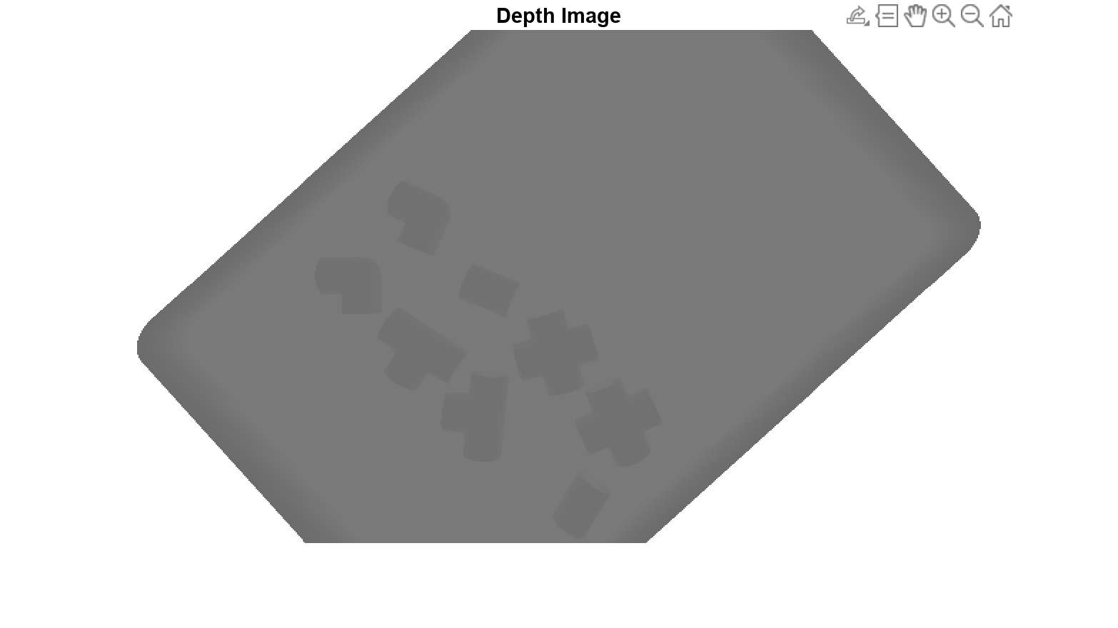
深度イメージを表示します。深度イメージは、カメラからシーン内の各ピクセルまでの距離、つまり深度を示します。
figure
imshow(imDepth);
title("Depth Image")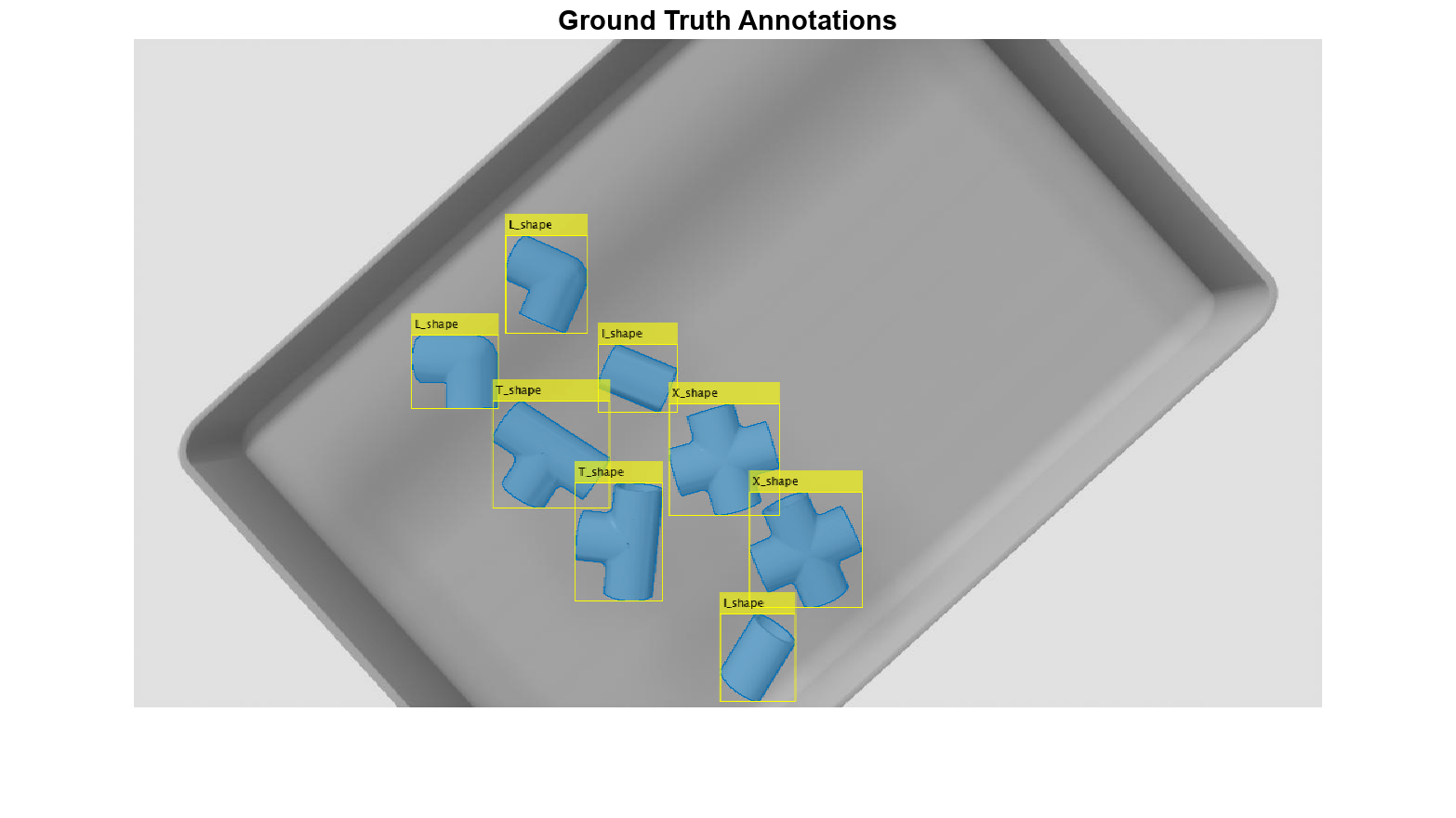
グラウンド トゥルース データの可視化
関数 insertObjectMask を使用して、元のイメージにグラウンド トゥルース マスクを重ね合わせます。
imRGBAnnot = insertObjectMask(imRGB,gtMasks,Opacity=0.5);
関数 insertObjectAnnotation を使用して、元のイメージにオブジェクトの境界ボックスを重ね合わせます。
imRGBAnnot = insertObjectAnnotation(imRGBAnnot,"rectangle",gtBoxes,gtClasses);元のイメージにグラウンド トゥルース マスクと境界ボックスを重ね合わせて表示します。
figure
imshow(imRGBAnnot);
title("Ground Truth Annotations")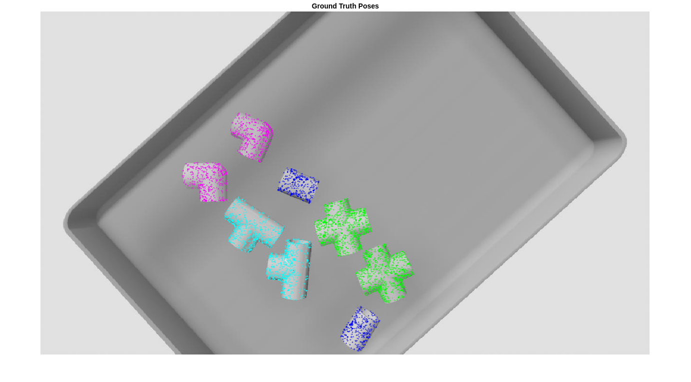
グラウンド トゥルース姿勢の可視化
オブジェクトの 3 次元回転と平行移動を可視化するには、各オブジェクト クラスの点群に姿勢変換を適用し、点群を元のイメージに表示します。姿勢変換された点群をイメージに投影すると、シーン内の機械部品の向きと完全に一致します。
各オブジェクト クラスに対応する姿勢の色、姿勢の色の数、オブジェクトの数を定義し、姿勢変換された点群を格納する RGB イメージ imGTPose のコピーを作成します。
poseColors = ["blue","green","magenta","cyan"];
numPoseColors = length(poseColors);
numObj = size(gtBoxes,1);
imGTPose = imRGB;
グラウンド トゥルース オブジェクトの姿勢を可視化するには、helperVisualizePosePrediction サポート関数を使用し、投影された点群をサンプル イメージに重ねて表示します。
gtPredsImg = helperVisualizePosePrediction(gtPoses, ...
    gtClasses, ...
    ones(size(gtClasses)), ...
    gtBoxes, ...
    modelClassNames, ...
    modelPointClouds, ...
    poseColors, ...
    imRGB, ...
    intrinsics);

figure
imshow(gtPredsImg);
title("Ground Truth Point Clouds")
事前学習済みの Pose Mask R-CNN モデルを使用した 6-DoF 姿勢の予測
posemaskrcnnオブジェクトを使用して、事前学習済みの Pose Mask R-CNN モデルを作成します。
pretrainedNet = posemaskrcnn("resnet50-pvc-parts");オブジェクト関数predictPoseを使用して、イメージ内の機械部品の 6-DoF 姿勢を予測します。予測信頼度のしきい値 Threshold を 0.5 に指定します。
[poses,labels,scores,boxes,masks] = predictPose(pretrainedNet, ...
                imRGB,imDepth,intrinsics,Threshold=0.5, ...
                ExecutionEnvironment="auto");
予測結果の可視化
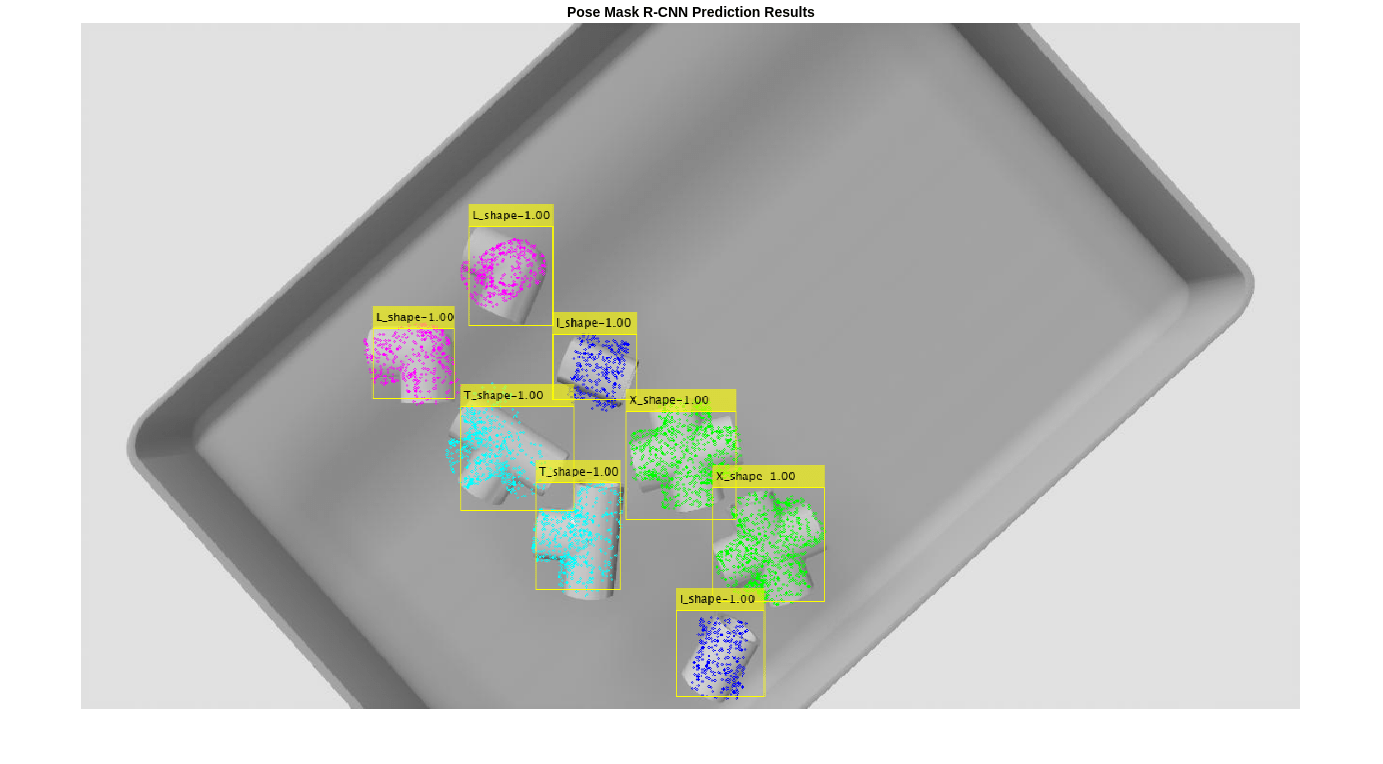
この例のグラウンド トゥルース姿勢の可視化セクションでグラウンド トゥルース姿勢を可視化するために使用したのと同じように、投影された点群を使用して、6-DoF 姿勢予測を表示します。予測されたオブジェクトの姿勢を可視化するには、helperVisualizePosePrediction サポート関数を使用し、投影された点群をサンプル イメージに重ねて表示します。
pretrainedPredsImg = helperVisualizePosePrediction(poses, ...
    labels, ...
    scores, ...
    boxes, ...
    modelClassNames, ...
    modelPointClouds, ...
    poseColors, ...
    imRGB, ...
    intrinsics);

figure;
imshow(pretrainedPredsImg);
title("Pose Mask R-CNN Prediction Results")
Pose Mask R-CNN ネットワークの予測をこのように可視化することで、ネットワークが 2 次元境界ボックスとクラス、およびビン内のパーツの 3 次元平行移動を正しく予測していることがわかります。3 次元回転はより困難なタスクであるため、予測には多少のノイズが伴います。結果を絞り込むため、推定済み姿勢の調整セクションで、深層学習の結果と従来の点群処理手法を組み合わせます。
推定済み姿勢の調整
深度イメージからの部分的な点群の取得
Pose Mask R-CNN ネットワークからの予測の精度を向上させるには、予測された姿勢と点群データの従来の幾何学的処理を組み合わせます。このセクションでは、深度イメージとカメラの内部パラメーターを使用して、シーンの点群表現を取得します。
後処理を使用して、遠くの壁や床の点など、ビンピッキング シーンの一部としては現実的に遠く離れ過ぎている点を削除します。カメラからの適切な最大距離、つまり最大深度を 0.5 に指定します。
maxDepth = 0.5;
PVC パーツが置かれているビンの表面を点群データから削除するには、シーン点群内のビンの表面に 3 次元平面を当てはめます。平面を当てはめる手順で使用する最大ビン距離とビンの向きを指定します。最大ビン距離は、ビンからカメラまでの最大距離の推定値です。簡単にするために、ビンは水平方向にあると仮定します。
maxBinDistance = 0.0015;
binOrientation = [0 0 -1];
サポート関数 helperPostProcessScene を使用して、深度イメージの生のシーン点群を後処理し、検出された各オブジェクトの点群を返します。
[scenePointCloud,roiScenePtCloud] = helperPostProcessScene(imDepth,intrinsics,boxes,maxDepth, ...
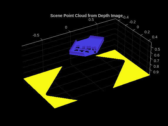
maxBinDistance,binOrientation);シーンの点群をプロットします。
figure;
pcshow(scenePointCloud,VerticalAxisDir="Down")
title("Scene Point Cloud from Depth Image")
深度イメージから抽出されたオブジェクト点群の 1 つをプロットします。
figure;
pcshow(roiScenePtCloud{end}, VerticalAxisDir="Down")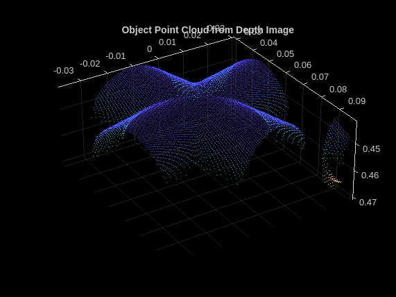
title("Object Point Cloud from Depth Image")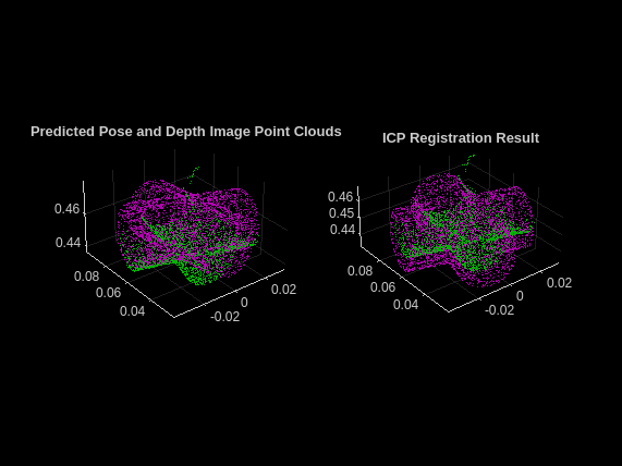
点群のレジストレーションおよび姿勢推定の調整
姿勢推定の結果を改善するには、関数pcregistericpを使用して、反復最近接点 (ICP) アルゴリズムに基づいて点群のレジストレーションを実行します。レジストレーション中に、Pose Mask R-CNN モデルによって予測されたオブジェクトの姿勢を、深度イメージからのオブジェクトの部分的な点群に揃えます。使用される点群の点の数を減らして計算時間を短縮するには、関数pcdownsampleを使用し、ダウンサンプリング係数を 0.25 に設定します。
downsampleFactor = 0.25;
numPreds = size(boxes,1);
registeredPoses = cell(numPreds,1);
for detIndex = 1:numPreds
    detClass = string(labels(detIndex));

    % Define predicted rotation and translation.
    detTform = poses(detIndex);
    detScore = scores(detIndex);

    % Retrieve the 3-D object point cloud of the predicted object class.
    ptCloud = modelPointClouds(modelClassNames == detClass);

    % Transform the 3-D object point cloud using the predicted pose.
    ptCloudDet = pctransform(ptCloud, detTform);

    % Downsample the object point cloud transformed by the predicted pose.
    ptCloudDet = pcdownsample(ptCloudDet,"random",downsampleFactor);

    % Downsample point cloud obtained from the postprocessed scene depth image.
    ptCloudDepth =  pcdownsample(roiScenePtCloud{detIndex},"random",downsampleFactor);

    % Run the ICP point cloud registration algorithm with default
    % parameters.
    [tform,movingReg] = pcregistericp(ptCloudDet,ptCloudDepth);
    registeredPoses{detIndex} = tform;
end
簡単にするために、単一の検出オブジェクトのレジストレーションを可視化します。左のサブプロットで、Pose Mask R-CNN 予測から取得された点群をマゼンタでプロットし、シーン深度イメージの後処理から取得された点群を緑でプロットします。右のサブプロットで、レジストレーションされた点群をマゼンタでプロットし、深度イメージ点群を緑でプロットします。
figure
subplot(1,2,1)
pcshowpair(ptCloudDet,ptCloudDepth)
title("Predicted Pose and Depth Image Point Clouds")

subplot(1,2,2)
pcshowpair(movingReg,ptCloudDepth)
title("ICP Registration Result")

Pose Mask R-CNN 予測姿勢と点群レジストレーションの組み合わせ
この大幅に改善された後処理と調整の手順の後、Pose Mask R-CNN ネットワークによって予測された姿勢を可視化します。3 次元の回転と平行移動で構成される 6-DoF 姿勢を rigidtform3d オブジェクトとして保存します。
refinedPoses = cell(1,numPreds);

for detIndex = 1:numPreds

    detClass = string(labels(detIndex));

    % Define predicted rotation and translation.
    detTform = poses(detIndex);
    detScore = scores(detIndex);

    % Rotation and translation from registration of depth point clouds.
    icpTform = registeredPoses{detIndex};

    % Combine the two transforms to return the final pose.
    combinedTform = rigidtform3d(icpTform.A*detTform.A);
    refinedPoses{detIndex} = combinedTform;

end
refinedPoses = cat(1,refinedPoses{:});

imPoseRefined = helperVisualizePosePrediction(refinedPoses, ...
    labels, ...
    scores, ...
    boxes, ...
    modelClassNames, ...
    modelPointClouds, ...
    poseColors, ...
    imRGB, ...
    intrinsics);

figure
imshow(imPoseRefined);
title("Pose Mask R-CNN + ICP")
投影された点は、イメージ内に存在する機械部品とより一致するようになり、回転結果もより正確になりました。
6-DoF 姿勢予測の評価
予測された 6-DoF オブジェクトの姿勢の品質を定量化したり評価したりするには、面取り距離 [3] を使用して、予測された姿勢によって変換された点群と、グラウンド トゥルース姿勢によって変換された同じ点群の最近接点の間の距離を測定します。面取り距離が小さいということは、予測された姿勢とグラウンド トゥルース姿勢が密接に一致していることを示します。より短い面取り距離で正確に姿勢が揃うようにするには、すべてのオブジェクト点群をグラウンド トゥルース姿勢 (緑) と予測姿勢 (マゼンタ) として表示します。
まず、サポート関数 helperEvaluatePosePrediction を使用して、グラウンド トゥルース姿勢と予測姿勢のオブジェクト点群間の面取り距離を計算します。
[distPtCloud,predIndices,gtIndices] = helperEvaluatePosePrediction( ...
    modelPointClouds,modelClassNames,boxes,labels,refinedPoses,gtBoxes,gtClasses,gtPoses);
次に、グラウンド トゥルース姿勢と予測姿勢の点群ペアを可視化し、helperVisualizeChamferDistance サポート関数を使用して、各オブジェクトの姿勢に対応する面取り距離値を表示します。
helperVisualizeChamferDistance(...
    labels, predIndices, gtIndices, modelPointClouds, ...
    modelClassNames, gtClasses, refinedPoses, gtPoses, distPtCloud);

avgChamferDistance = mean(distPtCloud(:));
sgtitle(["Pose Mask R-CNN Chamfer Distances" "Mean " + num2str(avgChamferDistance)], Color='w');
学習用データの準備
Pose Mask R-CNN 深層学習ネットワークを使用して、カスタム ビンピッキング データ セットで転移学習を実行します。データ セットには、Simulink® を使用して生成された 3 次元パイプ コネクタの RGB イメージと深度イメージが 100 個格納されています。データは、さまざまな視角やさまざまなライティング条件での、ビン内にランダムな向きで置かれた機械部品のイメージで構成されており、I、X、L、または T の形状をもつオブジェクトに対応する 4 つのオブジェクト クラスを含みます。データ セットには、各イメージ内のすべてのオブジェクトの境界ボックス、オブジェクト クラス、バイナリ マスク、6-DoF 姿勢情報、および 4 つのオブジェクト クラスごとの点群データも含まれます。
データ セットのダウンロード
サポート関数 helperDownloadPVCPartsDataset を使用してデータ セットをダウンロードします。この手順にはインターネット接続が必要です。
datasetUnzipFolder = helperDownloadPVCPartsDataset;
データの読み込みと分割
データを分割する前に、グローバルな乱数の状態を設定して、結果のより高い再現性を確保します。
rng("default");データ セットとグラウンド トゥルース データの場所を指定します。
datasetDir = fullfile(datasetUnzipFolder,"pvcparts100");
gtLocation = fullfile(datasetDir,"GT");
ビンピッキング データ セットから読み取るサポート関数 helperSimAnnotMATReader を使用して、fileDatastore オブジェクトを作成します。
dsRandom = fileDatastore(gtLocation, ...
    ReadFcn=@(x)helperSimAnnotMATReader(x,datasetDir));
データ セットを学習セットと検証セットにランダムに分割します。イメージの総数が比較的少ないため、データの比較的大部分 (70%) を学習に割り当て、30% を検証に割り当てます。
randIndices = randperm(length(dsRandom.Files));
numTrainRandom = round(0.7*length(dsRandom.Files));
dsTrain = subset(dsRandom,randIndices(1:numTrainRandom));
dsVal = subset(dsRandom,randIndices(numTrainRandom+1:end));
データ ローダーを使用して、最初の検証サンプルの RGB イメージ、深度イメージ、オブジェクト マスク、オブジェクト クラス、境界ボックス、姿勢、およびカメラの内部パラメーターをクエリします。
data = preview(dsVal);
imRGB = data{1};
imDepth = data{2};
gtMasks = data{5};
gtClasses = data{4};
gtBoxes = data{3};
gtPoses = data{6};
intrinsics = data{7};
クエリされたオブジェクト クラスが正しい順序を維持していることを確認します。
trainClassNames = categories(gtClasses)
trainClassNames = 4×1 cell array
    "'I_shape'"
    "'X_shape'"
    "'L_shape'"
    "'T_shape'"
Pose Mask R-CNN ネットワークの学習
Pose Mask R-CNN モデルには 3 つのステージで学習させます。
境界ボックス、クラス ラベル、およびセグメンテーション マスクの予測で構成されるインスタンス セグメンテーション タスクで、事前学習済みの Pose Mask R-CNN ネットワークに学習させます。この最初の学習手順では、深層ニューラル ネットワークの重みを初期化します。
検出された各オブジェクトの 3 次元回転と平行移動の予測で構成される姿勢推定タスクを、前の手順で学習させた Pose Mask R-CNN ネットワークに学習させます。
前の手順で学習させた Pose Mask R-CNN ネットワークに姿勢推定タスクを学習させて、回転予測を調整します。
可能であれば、1 つ以上の GPU で学習を行います。ある程度の速度を出すため、学習に GPU を使用することを強く推奨します。GPU を使用するには、Parallel Computing Toolbox™ ライセンスと CUDA® 対応の NVIDIA® GPU が必要です。詳細については、GPU 計算の要件 (Parallel Computing Toolbox)を参照してください。
3 つのステージの学習には、NVIDIA GeForce RTX 2080 Ti GPU でそれぞれ約 15 分、15 分、および 70 分かかります。
アンカー ボックスの推定
Pose Mask R-CNN ネットワークに学習させるには、以下の変数 doTrain を true に設定します。カスタム データ セットでネットワークに学習させるには、データに対して固有のアンカー ボックスの位置を推定します。100 個の学習イメージのサブセットから境界ボックスを推定します。関数estimateAnchorBoxesを使用してアンカー ボックスを推定します。
doTrain = false;

if doTrain
    numAnchors = 8;
    numImgSample = 100;
    numImgSample = min(numImgSample, length(dsTrain.Files));
    sampledBboxes = {};
    dsTmp = copy(dsTrain);
    for ii=1:numImgSample
        tmpData = read(dsTmp);
        randSelect = randi(size(tmpData{3},1));
        sampledBboxes{end+1} = tmpData{3}(randSelect,:);
    end
    blds = boxLabelDatastore(table(sampledBboxes'));
    [anchorBoxes,meanAnchorIoU] = estimateAnchorBoxes(blds,numAnchors);
end
Pose Mask R-CNN ネットワーク アーキテクチャの定義
posemaskrcnn オブジェクトを使用して、Pose Mask R-CNN 姿勢推定ネットワークを作成します。ResNet-50 を使用して作成された事前学習済みネットワークをベース ネットワークとして指定します。クラス名および推定されるアンカー ボックスを指定します。
if doTrain
    untrainedNetwork = posemaskrcnn("resnet50-pvc-parts",trainClassNames,anchorBoxes);
end
学習ステージ 1: インスタンス セグメンテーションの実行
学習オプションの指定
関数trainingOptions (Deep Learning Toolbox)を使用して、インスタンス セグメンテーション学習ステージ用のネットワーク学習オプションを指定します。SGDM ソルバーを使用して、オブジェクト検出器に最大 5 エポック学習させます。名前と値の引数 ValidationData を検証データ dsVal として指定します。中間のネットワーク チェックポイントを保存する場所を指定します。
if doTrain
    outFolder = fullfile(tempdir,"output","train_posemaskrcnn_stage1");
    mkdir(outFolder);
    ckptFolder = fullfile(outFolder, "checkpoints");
    mkdir(ckptFolder);
    disp(outFolder);

    optionsStage1 = trainingOptions("sgdm", ...
        InitialLearnRate=0.0001, ...
        LearnRateSchedule="piecewise", ...
        LearnRateDropPeriod=1, ...
        LearnRateDropFactor=0.5, ...
        MaxEpochs=5, ...
        Plot="none", ...
        Momentum=0.9, ...
        MiniBatchSize=1, ...
        ResetInputNormalization=false, ...
        ExecutionEnvironment="auto", ...
        VerboseFrequency=5, ...
        ValidationData=dsVal, ...
        ValidationFrequency=20, ...
        Plots="training-progress", ...
        CheckpointPath=ckptFolder,...
        CheckpointFrequency=2,...
        CheckpointFrequencyUnit="epoch");
end
/tmp/output/train_posemaskrcnn_stage1
Pose Mask R-CNN の学習
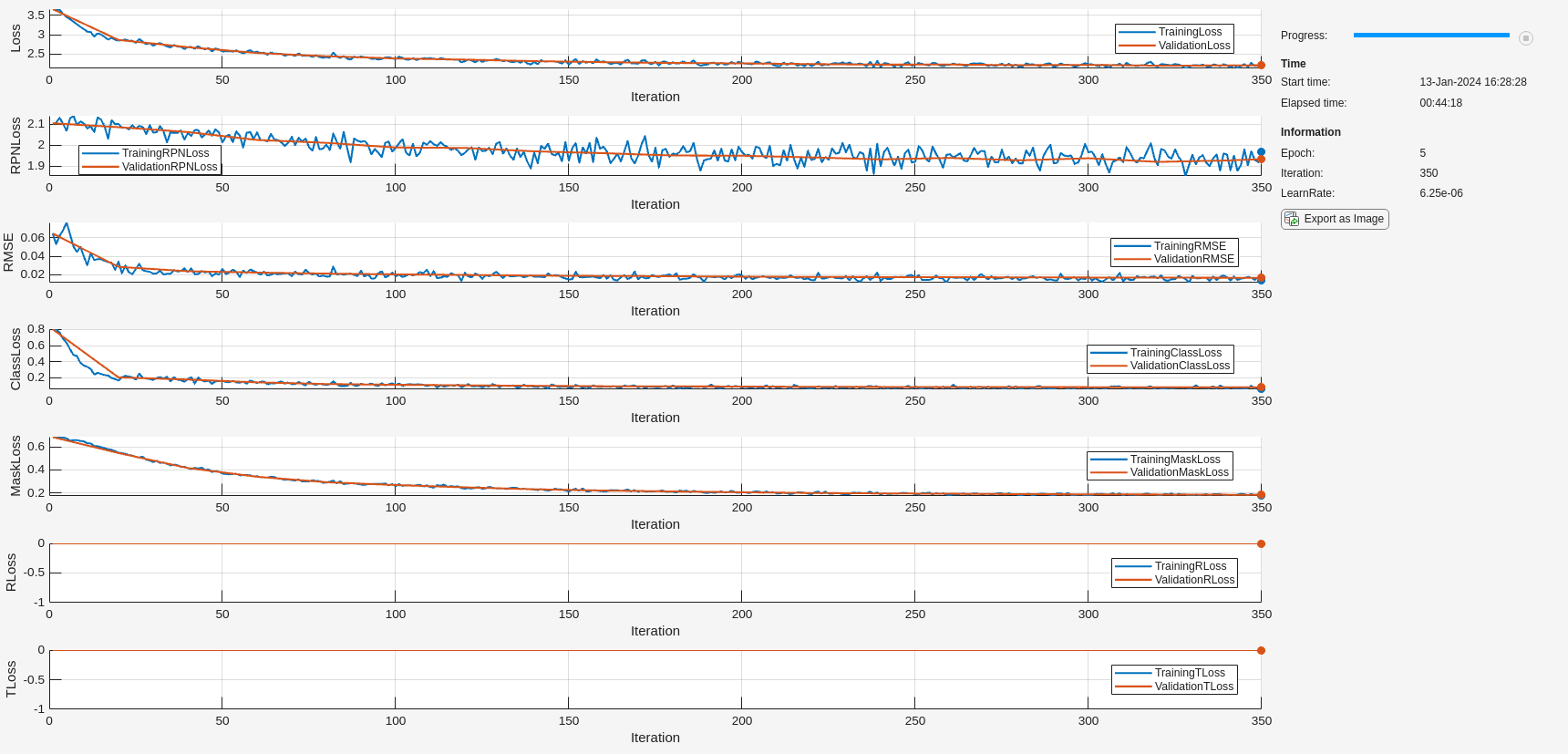
関数trainPoseMaskRCNNを使用して、Pose Mask R-CNN ネットワークに学習させ、境界ボックス、オブジェクト クラス、およびインスタンス セグメンテーション マスクを予測します。この学習手順では、姿勢またはマスク ヘッドの損失は使用されません。学習済みのネットワークをローカル フォルダーに保存し、複数の反復にわたる学習損失の進行状況をプロットします。
if doTrain
    [net, info] = trainPoseMaskRCNN(...
        dsTrain,untrainedNetwork,"mask",optionsStage1);

    modelDateTime = string(datetime("now", Format='yyyy-MM-dd-HH-mm-ss'));
    save(fullfile(outFolder,"stage1trainedPoseMaskRCNN-"+modelDateTime+".mat"),"net");
    disp(fullfile(outFolder,"stage1trainedPoseMaskRCNN-"+modelDateTime+".mat"))
end
学習ステージ 2: 姿勢の予測
学習オプションの指定
関数trainingOptions (Deep Learning Toolbox)を使用して、姿勢予測の学習ステージ用のネットワーク学習オプションを指定します。SGDM ソルバーを使用して、オブジェクト検出器に最大 5 エポック学習させます。名前と値の引数 ValidationData を検証データ dsVal として指定します。中間のネットワーク チェックポイントを保存する場所を指定します。このステージでは、3 次元の平行移動と回転の回帰損失を適用してネットワークに学習させます。
if doTrain
    outFolder = fullfile(tempdir,"output","train_posemaskrcnn_stage2");
    mkdir(outFolder);
    ckptFolder = fullfile(outFolder,"checkpoints");
    mkdir(ckptFolder);
    disp(outFolder);

    optionsStage2 = trainingOptions("sgdm", ...
        InitialLearnRate=0.0001, ...
        LearnRateSchedule="piecewise", ...
        LearnRateDropPeriod=1, ...
        LearnRateDropFactor=0.5, ...
        MaxEpochs=5, ...
        Plot="none", ...
        Momentum=0.9, ...
        MiniBatchSize=1, ...
        ResetInputNormalization=false, ...
        ExecutionEnvironment="auto", ...
        VerboseFrequency=5, ...
        ValidationData=dsVal, ...
        ValidationFrequency=20, ...
        Plots="training-progress", ...
        CheckpointPath=ckptFolder,...
        CheckpointFrequency=5,...
        CheckpointFrequencyUnit="epoch");
end
/tmp/output/train_posemaskrcnn_stage2
Pose Mask R-CNN の学習
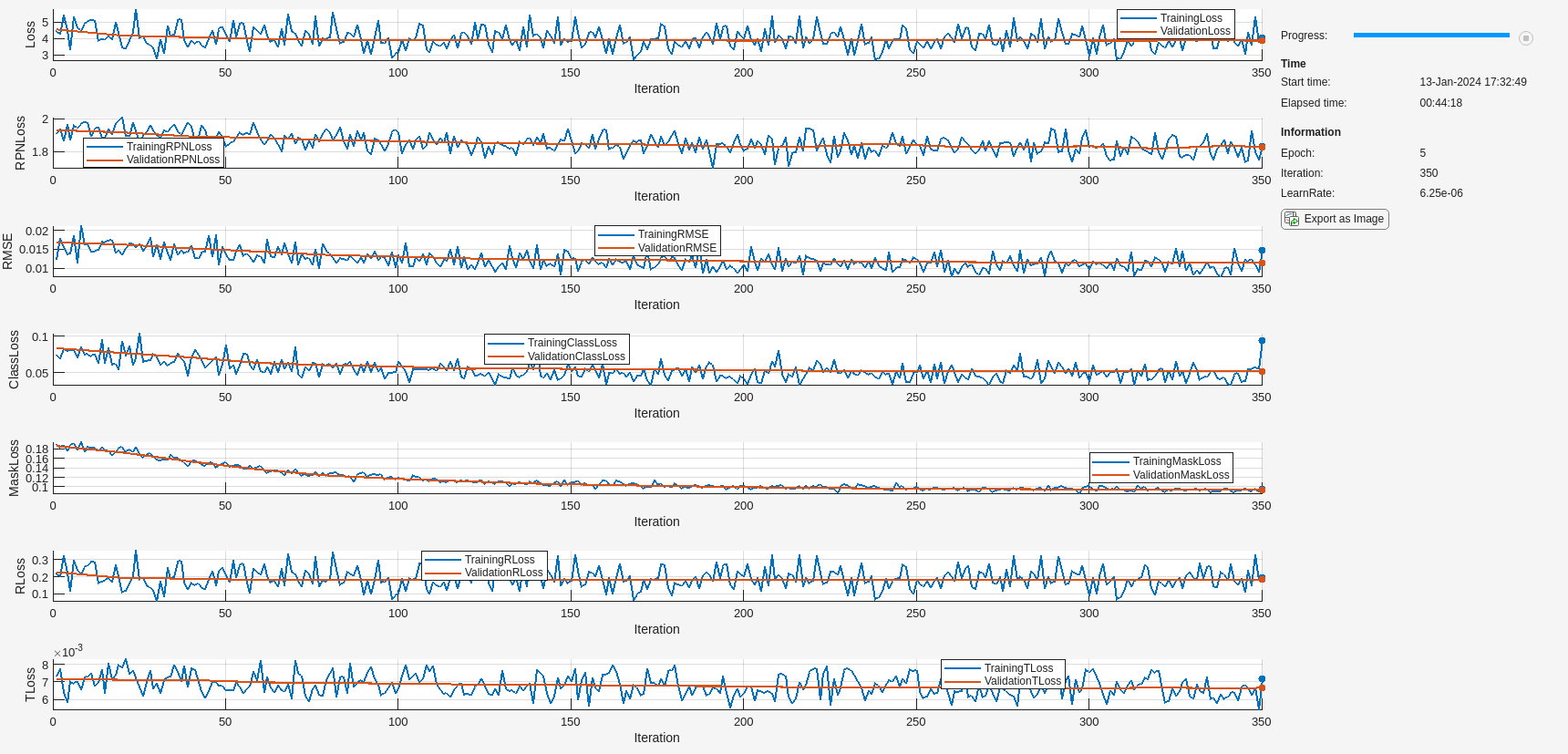
検出されたオブジェクトごとに 6-DoF 姿勢を予測するには、関数trainPoseMaskRCNNを使用して、インスタンス セグメンテーションを学習させた Pose Mask R-CNN ネットワーク net に、姿勢損失とマスク損失の両方を学習させます。学習済みのネットワークをローカル フォルダーに保存し、複数の反復にわたる回転と平行移動の学習損失の進行状況をプロットします。
if doTrain
    trainedNet = trainPoseMaskRCNN(...
        dsTrain,net,"mask-and-pose",optionsStage2);

    modelDateTime = string(datetime("now",Format="yyyy-MM-dd-HH-mm-ss"));
    save(fullfile(outFolder,"stage2trainedPoseMaskRCNN-"+modelDateTime+".mat"),"trainedNet");
    disp(fullfile(outFolder,"stage2trainedPoseMaskRCNN-"+modelDateTime+".mat"))

end
姿勢の推定
オブジェクト関数predictPoseを使用して、イメージ内の機械部品の 6-DoF 姿勢を予測します。予測信頼度のしきい値 Threshold を 0.5 に指定します。
if doTrain
    [poses,labels,scores,boxes,masks] = predictPose(trainedNet, ...
                data{1},data{2},data{end},Threshold=0.5, ...
                ExecutionEnvironment="auto");
姿勢予測を可視化します。
    image = data{1};
    intrinsics = data{end};
    trainedPredsImg = helperVisualizePosePrediction(poses, ...
        labels, ...
        scores, ...
        boxes, ...
        modelClassNames, ...
        modelPointClouds, ...
        poseColors, ...
        image, ...
        intrinsics);

    figure;
    imshow(trainedPredsImg);
    title("Pose Mask R-CNN Prediction Results After Stage 2")
end
6-DoF 姿勢予測を評価するには、helperEvaluatePosePrediction サポート関数を使用して、グラウンド トゥルース姿勢と予測姿勢のオブジェクト点群間の面取り距離を計算します。
if doTrain
    [distPtCloud,predIndices,gtIndices] = helperEvaluatePosePrediction( ...
        modelPointClouds,modelClassNames,boxes,labels,poses,gtBoxes,gtClasses,gtPoses);
end
次に、グラウンド トゥルース姿勢と予測姿勢の点群ペアを可視化し、helperVisualizeChamferDistance サポート関数を使用して、各オブジェクトの姿勢に対応する面取り距離値を表示します。平行移動の予測は正しいように見えますが、予測された回転にはグラウンド トゥルース姿勢とのずれが生じています。
if doTrain
    helperVisualizeChamferDistance(...
        labels, predIndices, gtIndices, modelPointClouds, ...
        modelClassNames, gtClasses, poses, gtPoses, distPtCloud);

    avgChamferDistance = mean(distPtCloud(:));
    sgtitle(["Pose Mask R-CNN Chamfer Distances After Stage 2" "Mean " + num2str(avgChamferDistance)], Color='w');
end

学習ステージ 3: 姿勢の調整
インスタンス セグメンテーションと姿勢推定のためにモデルに学習させた後、回転の予測を調整し、オブジェクトの対称性を考慮するために、モデルに対する第 3 ステージの学習を行います。
学習オプションの指定
trainingOptions (Deep Learning Toolbox)関数を使用して、姿勢調整の学習ステージ用のネットワーク学習オプションを指定します。SGDM ソルバーを使用して、オブジェクト検出器に最大 10 エポック学習させます。名前と値の引数 ValidationData を検証データ dsVal として指定します。中間のネットワーク チェックポイントを保存する場所を指定します。
if doTrain
    outFolder = fullfile(tempdir,"output","train_posemaskrcnn_stage3");
    mkdir(outFolder);
    ckptFolder = fullfile(outFolder,"checkpoints");
    mkdir(ckptFolder);
    disp(outFolder);

    optionsStage3 = trainingOptions("sgdm", ...
        InitialLearnRate=0.0001, ...
        LearnRateSchedule="piecewise", ...
        LearnRateDropPeriod=1, ...
        LearnRateDropFactor=0.5, ...
        MaxEpochs=10, ...
        Plot="none", ...
        Momentum=0.9, ...
        MiniBatchSize=1, ...
        ResetInputNormalization=false, ...
        ExecutionEnvironment="auto", ...
        VerboseFrequency=5, ...
        ValidationData=dsVal, ...
        ValidationFrequency=20, ...
        Plots="training-progress", ...
        CheckpointPath=ckptFolder, ...
        CheckpointFrequency=2, ...
        CheckpointFrequencyUnit="epoch");
end
/tmp/output/train_posemaskrcnn_stage3
Pose Mask R-CNN の学習
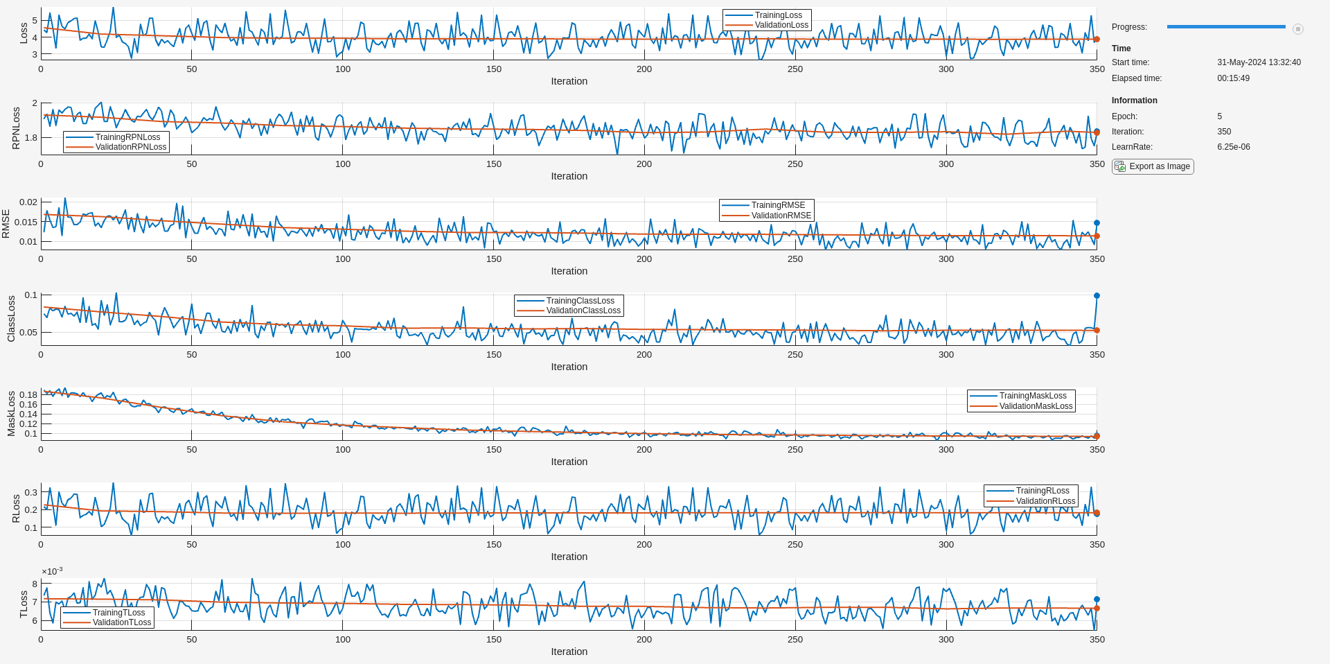
姿勢推定のための学習を行った Pose Mask R-CNN ネットワーク trainedNet に対し、trainPoseMaskRCNN関数を使用して、回転の予測を調整するための学習を行います。RotationLossWeight に既定値の 1 よりもはるかに大きな値を指定し、名前と値の引数 ReferencePointClouds をオブジェクト形状の 3 次元点群モデルとして指定します。学習済みのネットワークをローカル フォルダーに保存し、複数の反復にわたる回転と平行移動の学習損失の進行状況をプロットします。
if doTrain
    [refinedNet,info] = trainPoseMaskRCNN(...
        dsTrain, trainedNet,"pose-refinement",optionsStage3, ...
        FreezeSubNetwork=["rpn", "backbone"], ...
        RotationLossWeight=1e6, ...
        ReferencePointClouds = modelPointClouds);

    modelDateTime = string(datetime("now",Format="yyyy-MM-dd-HH-mm-ss"));
    save(fullfile(outFolder,"stage3trainedPoseMaskRCNN-"+modelDateTime+".mat"),"net");
    disp(fullfile(outFolder,"stage3trainedPoseMaskRCNN-"+modelDateTime+".mat"))
end
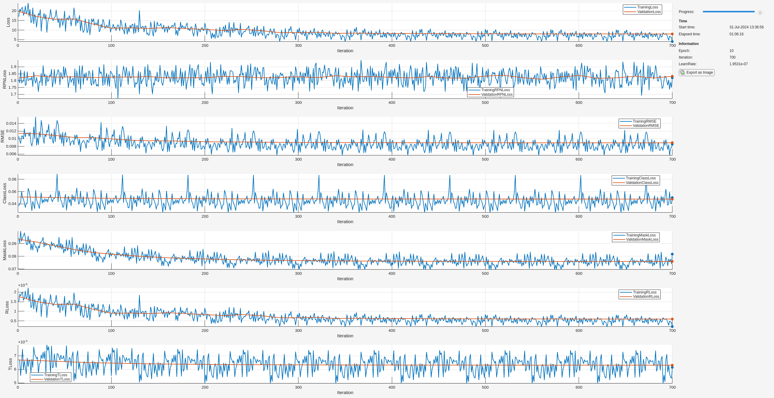
10 700 01:05:33 1.9531e-07 3.9928 1.8211 0.0085797 0.050034 0.081616 1.97e-06 0.0061428 7.9872 1.8307 0.0089327 0.047982 0.075946 5.9604e-06 0.0063155
姿勢の推定
オブジェクト関数predictPoseを使用して、イメージ内の機械部品の 6-DoF 姿勢を予測します。予測信頼度のしきい値 Threshold を 0.5 に指定します。
if doTrain
    [poses,labels,scores,boxes,masks] = predictPose(refinedNet, ...
                data{1},data{2},data{end},Threshold=0.5, ...
                ExecutionEnvironment="auto");
姿勢予測を可視化します。
    image = data{1};
    intrinsics = data{end};
    refinedPredsImg = helperVisualizePosePrediction(poses, ...
        labels, ...
        scores, ...
        boxes, ...
        modelClassNames, ...
        modelPointClouds, ...
        poseColors, ...
        image, ...
        intrinsics);

    figure;
    imshow(refinedPredsImg);
    title("Pose Mask R-CNN Prediction Results After Stage 3")
end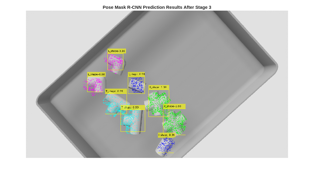
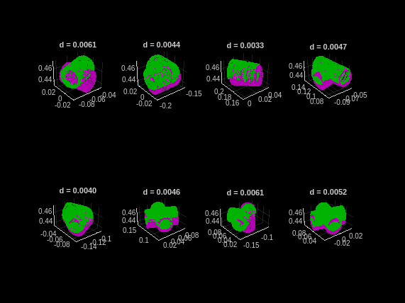
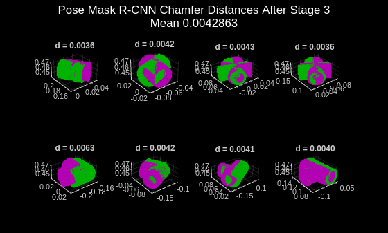
調整された 6-DoF 姿勢予測を評価するには、helperEvaluatePosePrediction サポート関数を使用して、グラウンド トゥルース姿勢と調整された予測姿勢のオブジェクト点群間の面取り距離を計算します。
if doTrain
    [distPtCloud,predIndices,gtIndices] = helperEvaluatePosePrediction( ...
        modelPointClouds,modelClassNames,boxes,labels,poses,gtBoxes,gtClasses,gtPoses);
end
次に、グラウンド トゥルース姿勢と予測姿勢の点群ペアを可視化し、helperVisualizeChamferDistance サポート関数を使用して、各オブジェクトの姿勢に対応する面取り距離値を表示します。このステージでは、学習の最初の 2 つのステージと比較して、モデルのパフォーマンスが大幅に向上しました。モデルの回転の予測をさらに改善するには、学習エポックの数を増やします。
if doTrain
    helperVisualizeChamferDistance(...
        labels,predIndices,gtIndices,modelPointClouds, ...
        modelClassNames,gtClasses,poses,gtPoses,distPtCloud);

    avgChamferDistance = mean(distPtCloud(:));
    sgtitle(["Pose Mask R-CNN Chamfer Distances After Stage 3" "Mean " + num2str(avgChamferDistance)],Color="w");
end
サポート関数
helperSimAnnotMATReader
function out = helperSimAnnotMATReader(filename,datasetRoot)
% Read annotations for simulated bin picking dataset
% Expected folder structure under `datasetRoot`:
%       depth/      (depth images folder)
%       GT/         (ground truth MAT files)
%       image/      (color images)

    data = load(filename);
    groundTruthMaT = data.groundTruthMaT;
    clear data;

    % Read RGB image.
    tmpPath = strsplit(groundTruthMaT.RGBImagePath, '\');
    basePath = {tmpPath{4:end}};
    imRGBPath = fullfile(datasetRoot, basePath{:});
    im = imread(imRGBPath);
    im = rgb2gray(im);
    if(size(im,3)==1)
        im = repmat(im, [1 1 3]);
    end

    % Read depth image.
    aa = strsplit(groundTruthMaT.DepthImagePath, '\');
    bb = {aa{4:end}};
    imDepthPath = fullfile(datasetRoot,bb{:}); % handle windows paths
    imD = load(imDepthPath); imD = imD.depth;

    % For "undefined" value in instance labels, assign to the first class.
    undefinedSelect = isundefined(groundTruthMaT.instLabels);
    classNames = categories(groundTruthMaT.instLabels);
    groundTruthMaT.instLabels(undefinedSelect) = classNames{1};
    if isrow(groundTruthMaT.instLabels)
        groundTruthMaT.instLabels = groundTruthMaT.instLabels';
    end

    % Wrap the camera parameter matrix into the cameraIntrinsics object.
    K = groundTruthMaT.IntrinsicsMatrix;
    intrinsics = cameraIntrinsics([K(1,1) K(2,2)], [K(1,3)  K(2,3)], [size(im,1) size(im, 2)]);

    % Process rotation matrix annotations.
    rotationCell = num2cell(groundTruthMaT.rotationMatrix,[1 2]);
    rotationCell = squeeze(rotationCell);

    % Process translation annotations.
    translation = squeeze(groundTruthMaT.translation)';
    translationCell = num2cell(translation, 2);

    % Process poses into rigidtform3d vector - transpose R to obtain the
    % correct pose.
    poseCell = cellfun( @(R,t)(rigidtform3d(R',t)), rotationCell, translationCell, ...
        UniformOutput=false);
    pose = vertcat(poseCell{:});

    % Remove heavily occluded objects.
    if length(groundTruthMaT.occPercentage) == length(groundTruthMaT.instLabels)
        visibility = groundTruthMaT.occPercentage;
        visibleInstSelector = visibility > 0.5;
    else
        visibleInstSelector = true([length(groundTruthMaT.instLabels),1]);
    end

    out{1} = im;
    out{2} = imD;                                                    % HxWx1 double array depth-map
    out{3} = groundTruthMaT.instBBoxes(visibleInstSelector,:);       % Nx4 double bounding boxes
    out{4} = groundTruthMaT.instLabels(visibleInstSelector);         % Nx1 categorical object labels
    out{5} = logical(groundTruthMaT.instMasks(:,:,visibleInstSelector));      % HxWxN logical mask arrays
    out{6} = pose(visibleInstSelector);                              % Nx1 rigidtform3d vector of object poses
    out{7} = intrinsics;                                             % cameraIntrinsics object

end
helperPostProcessScene
function [scenePtCloud,roiScenePtCloud] = helperPostProcessScene(imDepth,intrinsics,boxes,maxDepth,maxBinDistance,binOrientation)

    % Convert the depth image into an organized point cloud using camera
    % intrinsics.
    scenePtCloud = pcfromdepth(imDepth,1.0,intrinsics);

    % Remove outliers, or points that are too far away to be in the bin.
    selectionROI = [...
            scenePtCloud.XLimits(1) scenePtCloud.XLimits(2) ...
            scenePtCloud.YLimits(1) scenePtCloud.YLimits(2) ...
            scenePtCloud.ZLimits(1) maxDepth];
    selectedIndices = findPointsInROI(scenePtCloud, selectionROI);
    cleanScenePtCloud = select(scenePtCloud,selectedIndices);

    % Fit a plane to the bin surface.
    [~,~,outlierIndices] = pcfitplane(...
        cleanScenePtCloud,maxBinDistance,binOrientation);

    % Re-map indices back to the original scene point cloud. Use this
    % when cropping out object detections from the scene point cloud.
    origPtCloudSelection = selectedIndices(outlierIndices);

    % Crop predicted ROIs from the scene point cloud.
    numPreds = size(boxes,1);
    roiScenePtCloud = cell(1,numPreds);
    for detIndex=1:numPreds
        box2D = boxes(detIndex,:);

        % Get linear indices into the organized point cloud corresponding to the
        % predicted 2-D bounding box of an object.
        boxIndices = (box2D(2):box2D(2)+box2D(4))' + (size(scenePtCloud.Location,1)*(box2D(1)-1:box2D(1)+box2D(3)-1));
        boxIndices = uint32(boxIndices(:));

        % Remove points that are outliers from earlier pre-processing steps
        % (either belonging to the bin surface or too far away).
        keptIndices = intersect(origPtCloudSelection,boxIndices);
        roiScenePtCloud{detIndex} = select(scenePtCloud,keptIndices);
    end

end
helperVisualizeChamferDistance
function fig = helperVisualizeChamferDistance(...
    labels, predIndices, gtIndices, modelPointClouds, ...
    modelClassNames, gtClasses, poses, gtPoses, distances)
    fig = figure;

    for idx = 1:numel(predIndices)
        detIndex = predIndices(idx);

        if detIndex == 0
            % The ground truth bounding box does not match any predicted
            % bounding boxes (false negative)
            ptCloudTformDet = pointCloud(single.empty(0, 3));
        else
            detClass = string(labels(detIndex));
            gtIndex = gtIndices(idx);

            % Obtain the point cloud of the predicted object.
            ptCloudDet = modelPointClouds(modelClassNames == detClass);

            % Predicted 6-DoF pose with ICP refinement.
            detTform = poses(detIndex);

            % Apply the predicted pose transformation to the predicted object point
            % cloud.
            ptCloudTformDet = pctransform(ptCloudDet, detTform);
        end

        if gtIndex == 0
            % The predicted bounding box does not match any
            % ground truth bounding box (false positive).
            ptCloudTformGT = pointCloud(single.empty(0,3));
        else
            % Obtain the point cloud of the ground truth object.
            ptCloudGT = modelPointClouds(modelClassNames == string(gtClasses(gtIndex)));

            % Apply the ground truth pose transformation.
            ptCloudTformGT = pctransform(ptCloudGT,gtPoses(gtIndex));
        end

        subplot(2,4,gtIndex);
        pcshowpair(ptCloudTformDet,ptCloudTformGT);
        title(sprintf("d = %.4f",distances(idx)))
    end
end
helperVisualizePosePrediction
function image = helperVisualizePosePrediction(...
    poses, labels, scores, boxes, modelClassNames, modelPointClouds, poseColors, imageOrig, intrinsics)
    image = imageOrig;
    numPreds = size(boxes,1);
    detPosedPtClouds = cell(1,numPreds);
    for detIndex = 1:numPreds

        detClass = string(labels(detIndex));
        detTform = poses(detIndex);

        % Retrieve the 3-D object point cloud of the predicted object class.
        ptCloud = modelPointClouds(modelClassNames == detClass);

        % Transform the 3-D object point cloud using the predicted pose.
        ptCloudDet = pctransform(ptCloud, detTform);
        detPosedPtClouds{detIndex} = ptCloudDet;

        % Subsample the point cloud for cleaner visualization.
        ptCloudDet = pcdownsample(ptCloudDet,"random",0.05);

        % Project the transformed point cloud onto the image using the camera
        % intrinsic parameters and identity transform for camera pose and position.
        projectedPoints = world2img(ptCloudDet.Location,rigidtform3d,intrinsics);

        % Overlay the 2-D projected points over the image.helperVisualizeChamferDistance
        image = insertMarker(image,[projectedPoints(:,1), projectedPoints(:,2)],...
            "circle",Size=1,Color=poseColors(modelClassNames==detClass));
    end

    % Insert the annotations for the predicted bounding boxes, classes, and
    % confidence scores into the image using the insertObjectAnnotation function.
    LabelScoreStr = compose("%s-%.2f",labels,scores);
    image = insertObjectAnnotation(image,"rectangle",boxes,LabelScoreStr);
end
helperEvaluatePosePrediction
function [distADDS,predIndices,gtIndices] = helperEvaluatePosePrediction(...
    modelPointClouds, modelClassNames,boxes,labels,pose, gBox,gLabel,gPose)

% Compare predicted and ground truth pose for a single image containing multiple
% object instances using the one-sided Chamfer distance.

    function pointCloudADDS = pointCloudChamferDistance(ptCloudGT,ptCloudDet,numSubsampledPoints)
    % Return the one-sided Chamfer distance between two point clouds, which
    % computes the closest point in point cloud B for each point in point cloud A,
    % and averages over these minimum distances.

        % Sub-sample the point clouds
        if nargin == 2
            numSubsampledPoints = 1000;
        end

        rng("default"); % Ensure reproducibility in the point-cloud sub-sampling step.

        if numSubsampledPoints < ptCloudDet.Count
            subSampleFactor = numSubsampledPoints / ptCloudDet.Count;
            ptCloudDet = pcdownsample(ptCloudDet,"random",subSampleFactor);
            subSampleFactor = numSubsampledPoints / ptCloudGT.Count;
            ptCloudGT = pcdownsample(ptCloudGT,"random",subSampleFactor);
        end

        % For each point in GT ptCloud, find the distance to closest point in predicted ptCloud.
        distPtCloud = pdist2(ptCloudGT.Location, ptCloudDet.Location,...
                "euclidean", "smallest",1);

        % Average over all points in GT ptCloud.
        pointCloudADDS = mean(distPtCloud);

    end

    maxADDSThreshold = 0.1;

    % Associate predicted bboxes with ground truth annotations based on
    % bounding box overlaps as an initial step.
    minOverlap = 0.1;
    overlapRatio = bboxOverlapRatio(boxes,gBox);
    [predMatchScores, predGTIndices]  = max(overlapRatio, [], 2); % (numPreds x 1)
    [gtMatchScores, ~]  = max(overlapRatio, [], 1); % (1 x numGT)
    matchedPreds = predMatchScores > minOverlap;
    matchedGTs = gtMatchScores > minOverlap;

    numPreds = size(boxes,1);

    distADDS = cell(numPreds,1);
    predIndices = cell(numPreds,1);
    gtIndices = cell(numPreds,1);

    for detIndex=1:numPreds
        detClass = string(labels(detIndex));

        % Account for predictions unmatched with GT (false positives).
        if ~matchedPreds(detIndex)
            % If the predicted bounding box does not overlap any
            % ground truth bounding box, then maximum penalty is applied
            % and the point cloud matching steps are skipped.
            distADDS{detIndex} = maxADDSThreshold;
            predIndices{detIndex} = detIndex;
            gtIndices{detIndex} = 0;
        else
            % Match GT labels to Predicted objects by their bounding
            % box overlap ratio (box Intersection-over-Union).
            gtIndex = predGTIndices(detIndex);
            detClassname = string(detClass);
            gClassname = string(gLabel(gtIndex));

            if detClassname ~= gClassname
                % If predicted object category is incorrec, set
                % to maximum allowed distance (highly penalized).
                distADDS{detIndex} = maxADDSThreshold;
            else
                % Predicted rotation and translation.
                detTform = pose(detIndex);

                % Ground truth pose.
                gTform = gPose(gtIndex);

                % Get the point cloud of the object.
                ptCloud = modelPointClouds(modelClassNames == string(gClassname));

                % Apply the ground truth pose transformation.
                ptCloudTformGT = pctransform(ptCloud, gTform);

                % Apply the predicted pose transformation
                ptCloudDet = pctransform(ptCloud, detTform);

                pointCloudADDSObj = pointCloudChamferDistance(...
                    ptCloudTformGT,ptCloudDet);

                distADDS{detIndex} = pointCloudADDSObj;
            end
            predIndices{detIndex} = detIndex;
            gtIndices{detIndex} = gtIndex;
        end
    end

    distADDS = cat(1, distADDS{:});

    % Account for unmatched GT objects (false negatives).
    numUnmatchedGT = numel(matchedGTs) - nnz(matchedGTs);
    if numUnmatchedGT > 0
        % Set to max distance for unmatched GTs.
        falseNegativesADDS = maxADDSThreshold * ones(numUnmatchedGT,1);
        fnPred = zeros(numUnmatchedGT,1);
        fnGT = find(~matchedGTs);
        distADDS = cat(1, distADDS, falseNegativesADDS);
        predIndices = cat(1, predIndices, fnPred);
        gtIndices = cat(1, gtIndices, num2cell(fnGT'));
    end

    predIndices = cat(1, predIndices{:});
    gtIndices = cat(1, gtIndices{:});

end
helperDownloadPVCPartsDataset
function datasetUnzipFolder = helperDownloadPVCPartsDataset()
    datasetURL = "https://ssd.mathworks.com/supportfiles/vision/data/pvcparts100Dataset.zip";
    datasetUnzipFolder = fullfile(tempdir, "dataset");
    datasetZip = fullfile(datasetUnzipFolder,"pvcparts100Dataset.zip");
    if ~exist(datasetZip,"file")
        mkdir(datasetUnzipFolder);
        disp("Downloading PVC Parts dataset (200 MB)...");
        websave(datasetZip, datasetURL);
    end
    unzip(datasetZip, datasetUnzipFolder)
end
参考文献
[1] Yu Xiang, Tanner Schmidt, Venkatraman Narayanan, and Dieter Fox. "PoseCNN: A Convolutional Neural Network for 6D Object Pose Estimation in Cluttered Scenes." In Robotics: Science and Systems (RSS), 2018.
[2] Jiang, Xiaoke, Donghai Li, Hao Chen, Ye Zheng, Rui Zhao, and Liwei Wu. "Uni6d: A unified CNN framework without projection breakdown for 6d pose estimation." In Proceedings of the IEEE/CVF Conference on Computer Vision and Pattern Recognition, 2022.
[3] Gunilla Borgefors. "Hierarchical Chamfer matching: A parametric edge matching algorithm." In IEEE Transactions on Pattern Analysis and Machine Intelligence 10, no. 6 (1988): 849-865.
参考
trainPoseMaskRCNN | posemaskrcnn | predictPose | insertObjectMask | trainingOptions (Deep Learning Toolbox) | maskrcnn