このページの内容は最新ではありません。最新版の英語を参照するには、ここをクリックします。
Lamp
R2026aランプでの信号値を反映した色の表示
Lamp block

To add a block to a model, double-click the canvas and start typing the block name. Then, select the block from the list.
ライブラリ:
Simulink /
Dashboard
説明
Lamp ブロックは、接続している信号の値を示す色を表示します。シミュレーション中に必要な情報を示すように Lamp ブロックを設定するには、信号値と Lamp ブロックが表示する色を組み合わせた 1 つ以上の状態を指定します。Lamp ブロックをその他の Dashboard ブロックと共に使用し、モデル用にコントロールおよびインジケーターの対話型のダッシュボードを作成できます。
ランプ アイコン
いずれか 1 つの組み込みアイコンを選択するか、独自のカスタム アイコンをアップロードすることで、Lamp ブロックの外観を変更できます。組み込みアイコンには、基本的な形状、自動車関連のインジケーター ランプ、ワイヤレスのアイコンが含まれます。[アイコン] パラメーターを使用するか、ツールストリップ内のブロック タブを使用することで、Lamp ブロックのアイコンを変更できます。Dashboard ライブラリには、各アイコンに対してあらかじめ構成されたバージョンの Lamp ブロックをもつライブラリも含まれています。詳細については、アイコンを参照してください。

アイコンを選択するだけでなく Lamp ブロックの外観をカスタマイズする場合は、Customizable Blocks ライブラリの Lamp ブロックを使用して独自のインジケーター ランプを設計することを検討してください。
Dashboard ブロックの接続
Dashboard ブロックはモデル要素への接続に端子を使用しません。Dashboard ブロックを接続するには、接続モードを使用します。接続されていないブロックで接続モードに切り替えるには、接続するブロックをポイントし、[接続] ボタン  をクリックします。接続されているブロックで接続モードに切り替えるには、ブロックを選択すると表示される省略記号 (…) をポイントし、展開されるアクション メニューで [接続] ボタンをクリックします。
Display ブロックをモデル内の信号に接続したり Display ブロックの接続を変更したりするには、接続モードに切り替えます。接続する信号線を選択します。表示されるリストから、接続する信号を選択します。次に、Dashboard ブロックをポイントし、[接続完了] ボタン をクリックします。接続されたブロックの値を Dashboard ブロックに表示するには、シミュレーションを実行します。
Dashboard ブロックの接続の詳細については、Connect Dashboard Blocks to Simulink Modelを参照してください。
Dashboard ブロックは Stateflow® チャートにも接続できます。詳細については、Dashboard ブロックと Stateflow との接続 (Stateflow)を参照してください。
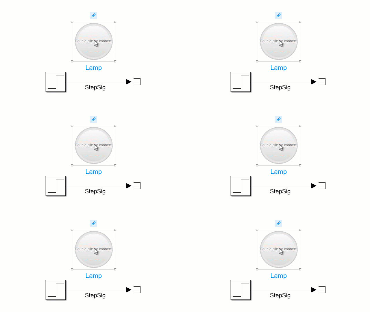
次のアニメーションは、Lamp ブロックをモデルに接続する方法を示しています。
例
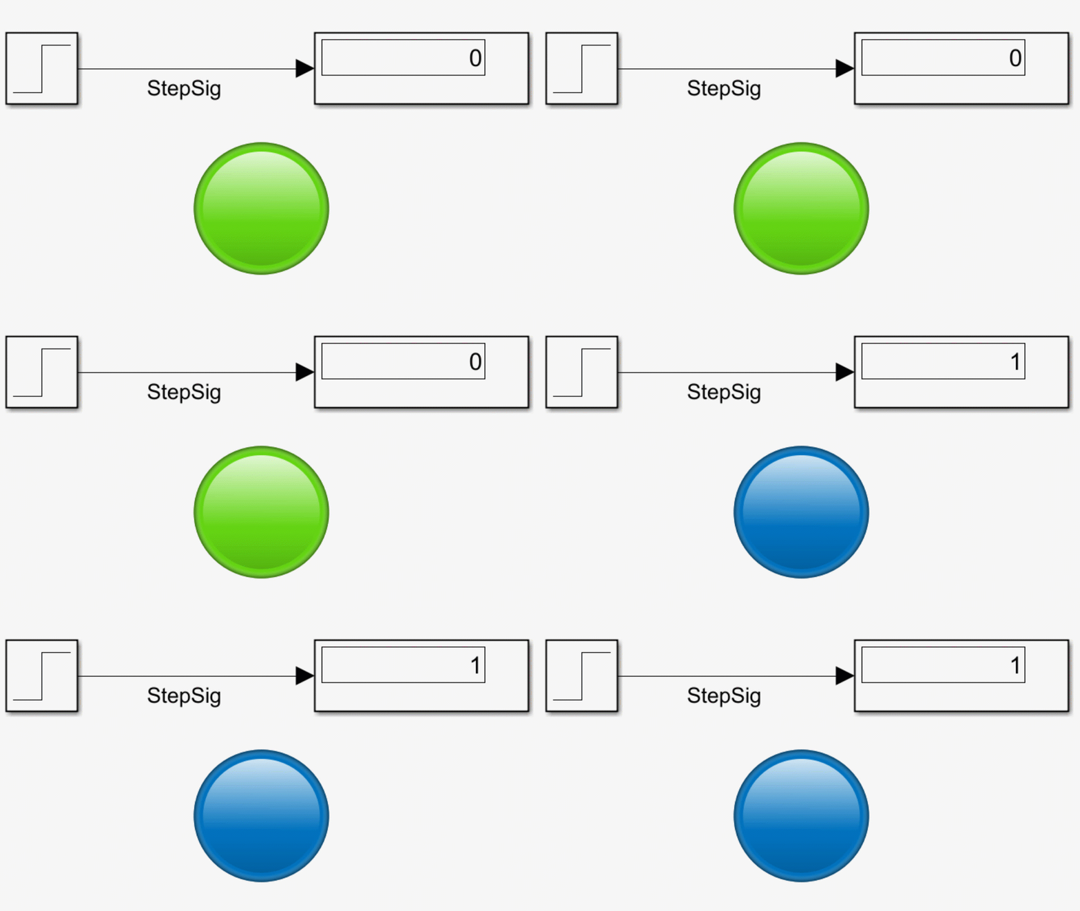
Lamp ブロックを使用して、接続されている信号の値を示すことができます。たとえば、モデル lampStep には、時間 3 に値を 0 から 1 に変更する Step ブロックが含まれています。Step ブロックからの出力信号 StepSig が Lamp ブロックに接続されています。
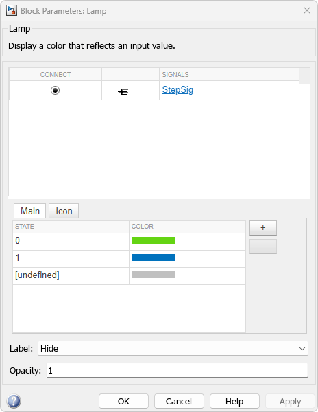
モデルのシミュレーションを実行します。StepSig の値が 0 の場合、ランプは緑色になります。StepSig の値が 1 の場合、ランプは青色になります。
拡張例

フォールトトレラント燃料制御システムのモデル化
この例では、Stateflow® と Simulink® の機能を組み合わせてハイブリッド システムをモデル化する方法を示します。このタイプのモデル化は、離散イベントに基づいて多数の可能な動作モードをもつシステムに対して特に便利です。従来の信号の流れが Simulink で処理されるのに対して、制御設定の変更は Stateflow で実装されます。この例で説明するモデルでは、ガソリン エンジンの燃料制御システムを表します。このシステムは、個々のセンサーの故障を検出し、制御システムが連続稼働用に動的に再設定されるという点で堅牢です。
制限
Dashboard Scope ブロックおよび Display ブロックを除き、Dashboard ブロックは実数のスカラー信号にのみ接続できます。
コメントアウトされたブロックには、[ブロック パラメーター] ダイアログ ボックスの [接続] テーブルを使用して Dashboard ブロックを接続することはできません。コメント化されたブロックに接続モードを使用して Dashboard ブロックを接続した場合、ブロックのコメントを解除するまでは Dashboard ブロックに接続された値が表示されません。
Dashboard ブロックは参照モデル内のモデル要素には接続できません。
モデルの階層構造をシミュレーションすると、参照モデル内の Dashboard ブロックで更新は実行されません。
Dashboard ブロックは、ラピッド アクセラレータ シミュレーションをサポートしていません。
シミュレーション中に Stateflow のチャート データやステート アクティビティに Dashboard ブロックを接続することはできません。
プログラムで Stateflow のチャート データやステート アクティビティに Dashboard ブロックを接続することはできません。
アクセラレータ モード シミュレーションのためのブロックの削減または最適化により、一部の信号にはシミュレーションで使用できるデータが含まれないことがあります。Dashboard ブロックを使用してこのような信号を表示するには、信号をログ記録用にマークします。
パラメーター
このブロックは、信号の値を表示するブロックである、Display ブロックです。表示する信号にブロックを接続します。
Dashboard ブロックはモデル要素への接続に端子を使用しません。Dashboard ブロックを接続するには、接続モード、Simulink® ツールストリップ、または [ブロック パラメーター] ダイアログ ボックスの [接続] テーブルを使用します。詳細については、Connect Dashboard Blocks to Simulink Modelを参照してください。
[接続] テーブルを使用して信号に接続する手順は以下のとおりです。
ブロックを選択します。
プロパティ インスペクターの [パラメーター] タブで、[接続] または [変更] をクリックします。
接続先となる信号の信号線を選択します。
表示されたテーブルで、信号を選択します。
[適用] をクリックします。
Dashboard ブロックは Stateflow チャートにも接続できます。詳細については、Dashboard ブロックと Stateflow との接続 (Stateflow)を参照してください。
プログラムでの使用
プログラムで Display ブロックを信号に接続できます。信号を表す Simulink.HMI.SignalSpecification オブジェクトを定義します。次に、Binding パラメーターの値をオブジェクトに設定します。Binding パラメーターの値を設定するには、set_param 関数を使用します。
たとえば、vdp という名前のモデルに、myGauge という名前の Circular Gauge ブロックと x1 という名前の信号が含まれているとします。ブロックを信号に接続するには、次のコードを使用します。
blockPath = "vdp/myGauge";
signalPath = "vdp/x1";

myObj = Simulink.HMI.SignalSpecification;
myObj.BlockPath = Simulink.BlockPath(signalPath);

set_param(blockPath,Binding=myObj)
| パラメーター: | Binding |
| 値: | Simulink.HMI.SignalSpecification object |
例: set_param(gcb,Binding=myObj)
各状態では [値] と [色] がペアになっています。
値 — 接続された信号の値
色 — 接続された信号が該当する値をもつ場合に Lamp ブロックで表示する色
状態を追加するには、[+] ボタンをクリックします。状態を削除するには、[状態] テーブルで状態の行を選択し、[X] ボタンをクリックします。
状態の値を編集するには、[値] 列で値をクリックし、値を削除してから、新しい値を入力します。色を編集するには、[色] 列で色をクリックし、新しい色を選択します。標準色のパレットから選択するか、RGB 値でカスタムの色を指定できます。
[undefined] の状態は、接続している信号の値が [状態] テーブルで指定されたどの値にも一致しない場合の Lamp ブロックの色を指定します。
プログラムでの使用
ブロック パラメーターの値をプログラムで設定するには、set_param 関数を使用します。
StateColors パラメーターの値を構造体の配列として指定します。ここで、各構造体は状態を表します。各構造体には次のフィールドが含まれます。
Value— 信号値Color— 接続された信号が該当する値をもつ場合に Lamp ブロックで表示する色
たとえば、現在選択されている Lamp ブロックに 2 つの状態を含めるとします。最初の状態では、接続されている信号の値が 0 の場合、ブロックで青色を表示します。2 番目の状態では、接続されている信号の値が 2 の場合、ブロックで赤色を表示します。これらの状態を実装するには、以下のコードを使用します。
state1.Value = 1;
state1.Color = [0 0 1];
state2.Value = 2;
state2.Color = [1 0 0];
myStates = [state1 state2];

set_param(gcb,StateColors=myStates)
| パラメーター: | StateColors |
| 値: | N-by-1 struct array, where N is the number of states and each struct has the fields Value and Color |
例: set_param(gcb,StateColors=myStates)
ColorDefault パラメーターは、接続している信号の値が指定された状態のどの値にも一致しない場合の Lamp ブロックの色を指定します。
| パラメーター: | ColorDefault |
| 値: | [0.7529 0.7529 0.7529] (既定値) | [r g b] vector with values between 0 and 1 |
例: set_param(gcb,ColorDefault=[1 0 1])
アイコンを使用して、モデル内での Lamp ブロックの外観を設定します。形状、自動車関連、ワイヤレスの組み込みアイコンから選択できます。または、独自のカスタム SVG ファイルをアイコンとしてアップロードできます。
アイコン オプションを表示するには、[アイコン] タブで [Icon Type] を選択します。独自の SVG ファイルをブロック アイコンとして使用するには、[カスタム] を [Icon Type] として選択し、SVG ファイルをアップロードします。Lamp ブロックの状態を示す色は次の SVG 要素に適用できます。
altGlyphcircleellipsepathpolygonrecttexttextPathtreftspan
形状アイコン
| アイコン | 基本形状のライブラリ ブロック名 | プログラムで使用する値 |
|---|---|---|
|
| Lamp | Default |
|
| Circle | Circle |
|
| Hexagon | Hexagon |
|
| Pentagon | Pentagon |
|
| Rectangle | Rectangle |
|
| Square | Square |
|
| Triangle | Triangle |
|
| Check1 | Check1 |
|
| Check2 | Check2 |
|
| Check3 | Check3 |
|
| Check4 | Check4 |
|
| Ex1 | Ex1 |
|
| Ex2 | Ex2 |
|
| Ex3 | Ex3 |
|
| Ex4 | Ex4 |
|
| Face | Face |
|
| Frown1 | Frown1 |
|
| Frown2 | Frown2 |
|
| Smile1 | Smile1 |
|
| Smile2 | Smile2 |
|
| Solid Face | SolidFace |
|
| Solid Frown1 | SolidFrown1 |
|
| Solid Frown2 | SolidFrown2 |
|
| Solid Smile1 | SolidSmile1 |
|
| Solid Smile2 | SolidSmile2 |


自動車関連アイコン
| アイコン | 自動車関連のインジケーター ランプのライブラリ ブロック名 | プログラムで使用する値 |
|---|---|---|
|
| Adaptive Cruise Control | AdaptiveCruiseControl |
|
| Adaptive Cruise Control Failure | AdaptiveCruiseControlFailure |
|
| Antilock Brake System | AntilockBrakeSystem |
|
| Battery | Battery |
|
| Check Engine | CheckEngine |
|
| Check Engine2 | CheckEngine2 |
|
| Cruise Control | CruiseControl |
|
| Eco Mode | EcoMode |
|
| Electronic Stability | ElectronicStability |
|
| Engine | Engine |
|
| Engine Coolant Temp | EngineCoolantTemp |
|
| Engine Failure | EngineFailure |
|
| Engine Heating | EngineHeating |
|
| Engine Oil | EngineOil |
|
| Exterior Bulb Failure | ExteriorBulbFailure |
|
| Front Fog Light | FrontFogLight |
|
| Fuel | Fuel |
|
| Hazards | Hazards |
|
| Headlamp Leveling | HeadlampLeveling |
|
| High Beams | HighBeams |
|
| Hill Descent Control | HillDescentControl |
|
| Lighting Switch | LightingSwitch |
|
| Low Beams | LowBeams |
|
| Parking Assistance | ParkingAssistance |
|
| Rear Fog Light | RearFogLight |
|
| Side Lights | SideLights |
|
| Stability Control | StabilityControl |
|
| Stability Control Off | StabilityControlOff |
|
| Tire Monitor | TireMonitor |
|
| Traction Control | TractionControl |
|
| Traction Control Off | TractionControlOff |
|
| Traction Control Failure | TractionControlFailure |
|
| Turn Signal Left | TurnSignalLeft |
|
| Turn Signal Right | TurnSignalRight |


ワイヤレス アイコン
| アイコン | アイコン名 | プログラムで使用する値 |
|---|---|---|
|
| Network | Network |
|
| Network No Signal | NetworkNoSignal |
|
| Network Transmission | NetworkTransmission |
|
| Network3G | Network3G |
|
| Network4G | Network4G |
|
| Network5G | Network5G |


ヒント
ツールストリップ内のブロック タブを使用して、Lamp ブロックのアイコンを変更できます。
Dashboard ライブラリには、各アイコンに対してあらかじめ構成された Lamp ブロックをもつライブラリがあります。
アイコンを選択するだけでなく Lamp ブロックの外観をカスタマイズする場合は、Customizable Blocks ライブラリの Lamp ブロックを使用して独自のインジケーター ランプを設計することを検討してください。
プログラムでの使用
ブロック パラメーターの値をプログラムで設定するには、set_param 関数を使用します。
| パラメーター: | Icon |
| 値: | 'Default' (既定値) | icon name formatted as string or character vector |
例: set_param(gcb,Icon="NetworkTransmission")
ブロック ラベルの位置。ブロックがモデル内の要素に接続されている場合、ラベルは接続された要素の名前です。
プログラムでの使用
ブロック パラメーターの値をプログラムで設定するには、set_param 関数を使用します。
| パラメーター: | LabelPosition |
| 値: | 'Top' (既定値) | "Top" | "Bottom" | "Hide" |
例: set_param(gcb,LabelPosition="Bottom")
ブロックの不透明度。0 ~ 1 のスカラー値として指定します。
プログラムでの使用
ブロック パラメーターの値をプログラムで設定するには、関数 set_param を使用します。
| パラメーター: | Opacity |
| 値: | '1' (既定値) | scalar with values between 0 and 1 formatted as string or character vector |
例: set_param(gcb,Opacity="0.5")
ブロックの特性
データ型 |
|
直達 |
|
多次元信号 |
|
可変サイズの信号 |
|
ゼロクロッシング検出 |
|

