Automated Generation and Deployment of ros2_control Plugin for Trajectory Controller
This example shows how to generate a ros2_control plugin for a trajectory controller model designed in Simulink® and integrate it into an existing ROS 2 project. This example adds ROS 2 Control interfaces to the UR5e manipulator trajectory controller model designed in the previous step, Automated Generation and Deployment of ros2_control Plugin for Trajectory Controller, and generates the ros2_control plugin.
It also shows how to deploy the generated ros2_control plugin as a library to a ROS 2 device running Gazebo simulation of the UR5e manipulator, and launch the controller.
To run this example, you must have ros2_control packages installed on your Linux machine. For related installation instructions, see ros2_control Github Repository.
Build ROS 2 Docker Image
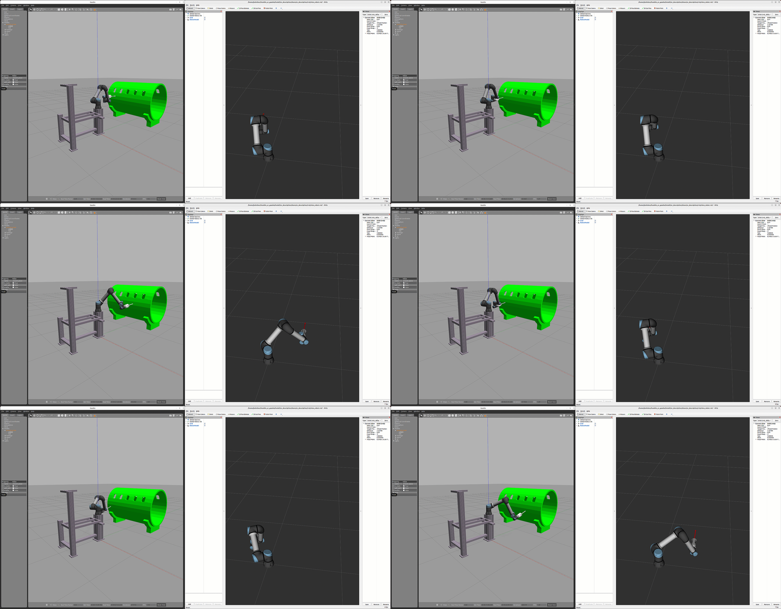
The Docker contains a sample ready-to-use Gazebo scene and ROS 2 package with hardware interfaces for UR5e manipulator. The Gazebo scene is modeled with the same set of mesh files used in the Automated Generation and Deployment of ros2_control Plugin for Trajectory Controller example.
Download the ROS 2 Docker file by cloning ROS Toolbox Docker Files. Follow these instructions below to build a Docker image pre-configurd with ROS 2 and Gazebo.
Open a Terminal in Linux and navigate to the 'S
upport-and-Docker-Files-For-ROS-Toolbox'folder.Build the Dockerfile by executing this command:
docker build -t jazzy_docker_image_noble ros_jazzy/Ubuntu/gazebocommand.jazzy_docker_image_nobleis the docker image name.
The Docker image is based on Ubuntu® Linux® and supports the ros2_control examples in ROS Toolbox.
Create a docker container by running this command below in a Linux Terminal:
$ docker run -it --net=host -v /dev/shm:/dev/shm --name ur_simulink_ros2_control_env jazzy_docker_image_noble
You can use these options with docker run command.
-it--- Start an interactive container.-net=host--- Use the host's network interfaces directly.--name--- Name the container. In this example you name the containerros2_sign_follower_robot.-v---Create storage space inside a container.
If you are using your own hardware implementation or actual hardware, ensure that the hardware drive is compatible with ros2_control architecture. You may need to modify the launch file to bring up the generated controller from Simulink as well.
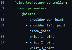
To get a list of joint names, you may refer to either the hardware specification, source code, or existing controllers listed in the YAML file under config folder.
For example, joint names for UR5e manipulator used in this exmaple can be found under Universal_Robots_ROS2_GZ_Simulation Github repository at ur_simulation_gz/config/ur_controllers.yaml
Configure ros2_control Settings
In the previous step, you verified the trajectory controller using an Unreal engine scene. In this step, you add ROS 2 control interfaces to the designed controller and modify it to be ros2_control compatible.
open_system("shapeTracingController_ros2.slx")Warning: Error evaluating <a href="matlab:Simulink.internal.OpenCallbackParamsDialog(['shapeTracingController_ros2/Subscribe'],'LoadFcn');">'LoadFcn'</a> callback of ROS2 Subscribe block (mask) '<a href="matlab:open_and_hilite_hyperlink ('shapeTracingController_ros2/Subscribe','error')">shapeTracingController_ros2/Subscribe</a>'.
Callback string is 'ros.slros2.internal.block.SubscribeBlockMask.messageLoadFcn(gcb);
'
Warning: Invalid or deleted object.
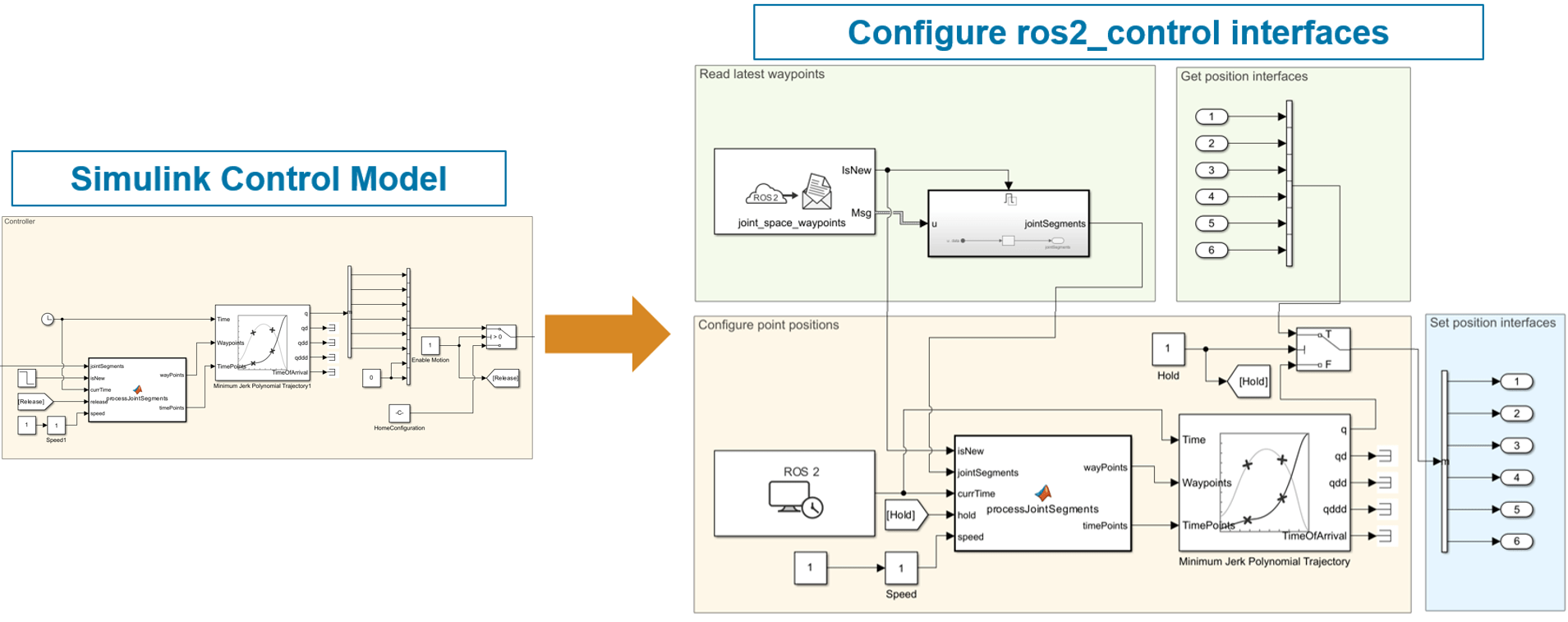
As shown above, you make these modifications to the controller model:
Replace the Clock with the ROS 2 Current Time block as the ROS 2 time source.
Use Inport blocks as state interfaces for each joint. This interface enables the controller to read the current joint states of the manipulator.
Use Outport blocks as command interfaces for each joint. This interface enables the controller to send commands to change the joint states of the manipulator.
Add Publish and/or Subscribe blocks to debug intermediate values while the controller is running on the ROS 2 network.
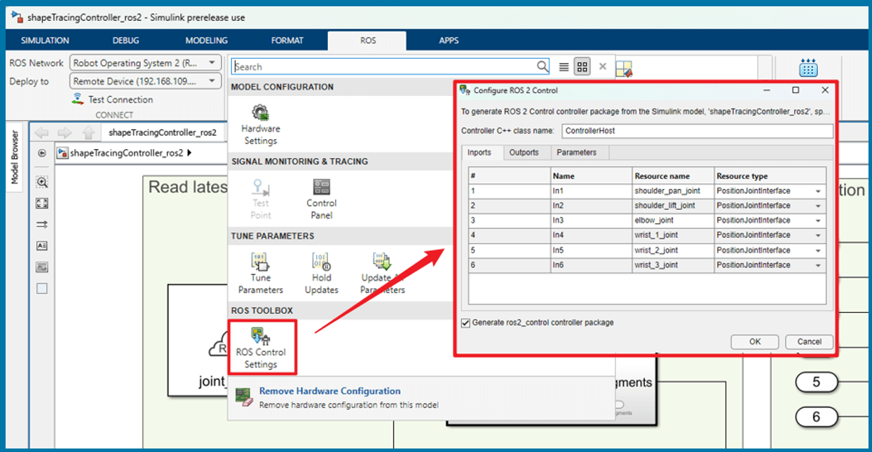
From the ROS tab in the toolstrip, click ROS Control Settings from the Prepare section. In the ROS 2 Control dialog, you map the inport and outports to the state and command interfaces of the UR5e manipulator. You also select any model parameters which you desire to be dynamically reonfigurable parameters for the deployed controller.
Generate ros2_control Plugin for 3-D Trajectory Controller
To generate the ros2_control plugin library and deploy directly to the remote device (virtual machine or target hardware), configure the remote device settings under ROS > CONNECT > Deploy to. Make sure ROS 2 and ROS 2 control is available on the device. You may use Test Connection button to ensure connection between host machine and target device.
Click 'Build' button to generate ros2_control plugin and deploy to target device.
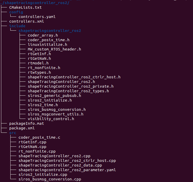
The generated ROS 2 package follows the ros2_control framework and you can see similar file structure as below:
controllers.xmlfile - Describes the generated library, including path, name, type for easy locate and load.config/controllers.yamlfile - Provides controller contents to be copied to controller configuration file.
If you are deploying and integrating the controller on your custom hardware, you must copy the content to your hardware's controller configuration YAML file. This enables the controller manager to launch the deployed controller:
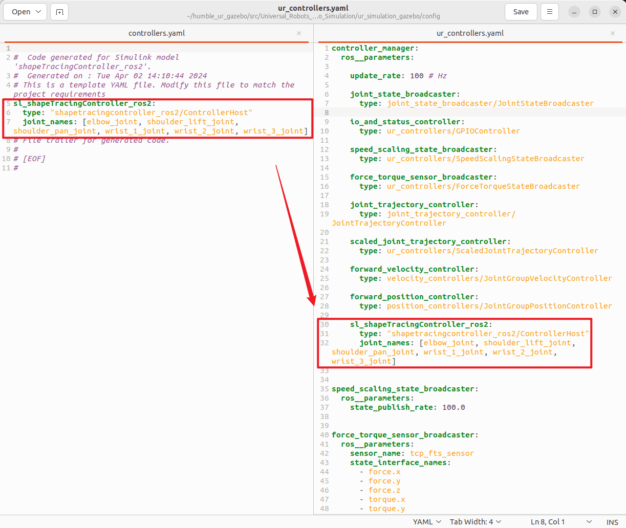
Note that if you are generating the controller library into a separate folder, you must source the setup.bash file under its install sub-directory.
Integrate Deployed Controller and Start Gazebo Simulation in Docker
Copy the generated source code from Linux machine to the docker container. This command copies the shapeTracingController_ros2 source code folder from Linux directory ~/sl_ur_demo/src/ to docker container directory /home/user/sl_ur_demo/src/.
$ docker cp ~/sl_ur_demo/src/shapeTracingController_ros2 ur_simulink_ros2_control_env:home/user/ros2_ws/sl_ur_demo/src
Connect to the docker container by running this command in a Linux Terminal:
$ docker exec -it ur_simulink_ros2_control_env /bin/bash
In the docker container terminal, run these commands to build and launch the project.
$ cd /home/user/ros2_ws
$ source /opt/ros/jazzy/setup.bash
$ colcon build
$ source ./install/setup.bash
$ ros2 launch ur_simulation_gazebo ur_sl.launch.py
You can use ros2 control APIs to verify that the controller is active and position interfaces have been claimed.
$ ros2 control list_controllers
$ ros2 control list_hardware_interfaces
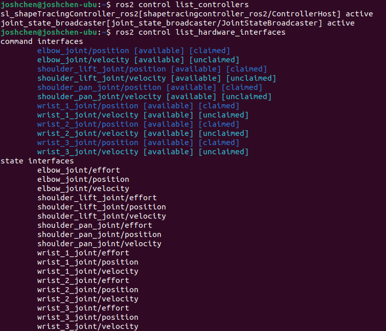
To view the Gazebo World, open any web browser and connect the host port you used to configure your Docker image. This example connects to localhost:8080.
Tune Parameters and Verify the Deployed Controller with Gazebo
The generated ros2_control plugin can be used robot-agnostically as long as the joint interfaces are the same. Otherwise, you must modify joint interface names and types in the Simulink model and regenerate the code.
The launch file used in this example has been customized to launch the generated controller from Simulink. If you are trying this workflow with your own hardware or simulator, ensure you also update the launch file to launch the generated controller.
Launch nodes to start hardware, controller, Gazebo, and Rviz.
$ ros2 launch ur_simulation_gazebo ur_sl.launch.py
It is quite normal that one would have to tune their controllers after deploying to actual target machine. Here, we use Gazebo to showcase the convenience of tunning parameters by utilizing ROS 2 Control framework.
When the controller is in “Active” lifecycle state, you can tune parameters as shown below to see real-time behavior change in Gazebo.
Send waypoint message from
MATLABor target terminal, and observe that the robot is still not moving.
% Load joint configuration from simulation
load('ur5e_joint_configuration.mat')
% Create a publisher and send out the joint configuration to /joint_space_waypoints topic
node = ros2node('/matlab_node');
[pub,msg] = ros2publisher(node,'/joint_space_waypoints','std_msgs/Float64MultiArray');
msg.data = reshape(jointConfigs,1,numel(jointConfigs),1);
send(pub,msg)
Release joint position lock by running the following command on target terminal.
$ ros2 param set /sl_shapeTracingController_ros2 Hold_Value false
Speed up the movement by running the following command on target terminal.
$ ros2 param set /sl_shapeTracingController_ros2 Speed 2.0
If anything unexpected happens, the controller resets itself to default state and goes back to “Unconfigured” lifecycle state. You can use controller manager to configure and activate the controller again when ready.
