Simulink を使用した RoadRunner シナリオへのセンサーの追加
Simulink® でセンサー モデルを定義し、それらを RoadRunner シナリオの車両アクターに追加します。その後、RoadRunner Scenario からグラウンド トゥルース測定値を取得し、それらを Simulink で検出として処理して可視化します。
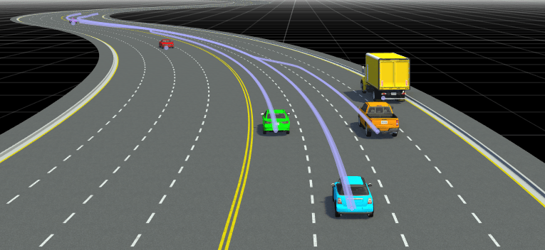
この例では、レーダー、ビジョン センサー、および LiDAR を RoadRunner シナリオの車両に追加します。
RoadRunner Scenario のセットアップ — Simulink インターフェイス
RoadRunner のインストール フォルダーとプロジェクト フォルダーのプロパティを構成します。RoadRunner アプリを開きます。
rrInstallationPath = "C:\Program Files\RoadRunner R2025b\bin\win64";
rrProjectPath = "D:\RR\TestProjects";

s = settings;
s.roadrunner.application.InstallationFolder.PersonalValue = rrInstallationPath;
rrApp = roadrunner(rrProjectPath);
この例で使用するシナリオを開くには、例のフォルダーから RoadRunner プロジェクト フォルダーに次のファイルを追加する必要があります。
straightCurvedFourLaneRoad.rrscene— 4 車線のハイウェイを記述する RoadRunner シーン ファイル。SensorDetectionSimulation.rrscenario— アクターと 4 車線ハイウェイ シーンにおけるアクターの軌跡を記述する RoadRunner シナリオ ファイル。SensorIntegration.rrbehavior.rrmeta— Simulink を使用したセンサー検出処理と可視化の動作を RoadRunner シナリオのエゴ ビークルに関連付ける動作ファイル。
copyfile("straightCurvedFourLaneRoad.rrscene",fullfile(rrProjectPath,"Scenes/"));
copyfile("SensorDetectionSimulation.rrscenario",fullfile(rrProjectPath,"Scenarios/"))
copyfile("SensorIntegration.rrbehavior.rrmeta",fullfile(rrProjectPath,"Assets","Behaviors/"))
シナリオを開き、Simulink を RoadRunner シナリオと接続するための ScenarioSimulation オブジェクトを作成します。
openScenario(rrApp,"SensorDetectionSimulation")
rrSim = createSimulation(rrApp);
Connection status: 1
Connected to RoadRunner Scenario server on localhost:60729, with client id {1c94acd7-2f67-42f1-b7b3-adb802f3fbc4}
SensorSimulation オブジェクトの作成後に RoadRunner シーンを変更する場合は、変更を MATLAB で正しく反映するために次の手順に従う必要があります。
RoadRunner アプリケーションを保存して閉じます。
MATLAB ワークスペースから
ScenarioSimulationオブジェクトをクリアします。RoadRunner シナリオを再度開きます。
ScenarioSimulationオブジェクトを再作成します。
RoadRunner シナリオ シミュレーションのステップ サイズを指定します。Simulink モデルでも同じステップ サイズが使用されます。単位は秒です。
simStepSize = 0.1;
set(rrSim,"StepSize",simStepSize);
Simulink モデルの検証とシナリオのシミュレーション
Simulink モデル rrScenarioSimWithSensors は、Vision Detection Generatorブロック、Driving Radar Data Generatorブロック、Lidar Point Cloud Generatorブロックをそれぞれ使用して、ビジョン センサー、レーダー センサー、LiDAR センサーのセンサー モデルを構成します。さらに、センサー ブロックが処理して検出にするグラウンド トゥルース オブジェクトと車線境界線のデータをシナリオから読み取るようにIdeal Ground Truth Sensorを構成します。また、エゴ ビークルに対して定義されているパスを RoadRunner シナリオから読み取り、パス追従ロジックを実装してパスに沿ってエゴ ビークルの動きを制御します。
このモデルは、RoadRunner Asset Library の CompactCar アセットを使用して表現される、エゴ ビークルに対するセンサーの取り付けパラメーターを定義します。RoadRunner Asset Library がインストールされていない場合は、エゴ ビークルのモデル化に使用しているアセットの寸法に基づいて、センサーの取り付け位置を調整します。
バス定義を読み込み、モデルを開きます。LiDAR センサー モデルのブロックにはグラウンド トゥルース ターゲット姿勢の入力は必要がないことに注意してください。
load("busDefinitionsForRRSim.mat")
modelName = 'rrScenarioSimWithSensors';
open_system(modelName)

シナリオおよびセンサー検出を可視化するには、鳥瞰図スコープ アプリを使用します。Simulink ツールストリップの [結果の確認] で [鳥瞰図スコープ] をクリックします。
シナリオのシミュレーションを開始します。モデルにより、シミュレーション中に Point Cloud Viewer ブロックを使用して 3 次元点群が可視化されます。鳥瞰図スコープで、2 次元点群、オブジェクト検出、車線検出をグラウンド トゥルース値と一緒に可視化できます。
set(rrSim,"SimulationCommand","Start")

参考
アプリ
ブロック
- RoadRunner Scenario Reader | RoadRunner Scenario Writer | Driving Radar Data Generator | Lidar Point Cloud Generator | Vision Detection Generator