RoadRunner Scenario Reader
Libraries:
Automated Driving Toolbox /
RoadRunner Scenario
Description
The RoadRunner Scenario Reader block reads the selected topic from the
RoadRunner scenario. You can set the Topic Category
parameter to Actor, Action,
Sensor, or Event. The block outputs
data as messages.
When you select the Actor topic, the block outputs the data
associated with the actor, such as Actor Specifications and
Actor Pose. When you select the Action
topic, the block outputs data such as Speed Change and
Lane Change. The block returns the simulation states from the previous
time step. You can filter data based on the actor associated with the Simulink® actor model.
When you select the Sensor topic, the block outputs the data
associated with the sensor of specified Sensor ID. You can select the
type of sensor data the block must output by specifying Target
Poses or Lane Boundaries. When you select the
Event topic, the block outputs data for the user-defined event
specified for the Event name parameter.
Examples
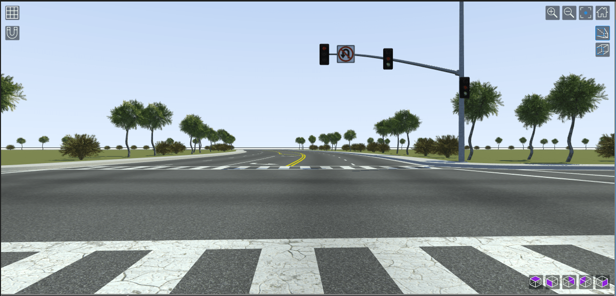
This example shows how you can read traffic signal information from a RoadRunner Scenario simulation in a Simulink actor behavior model. The vehicle associated with the behavior model regulates its speed in response to an approaching traffic signal.
Set Up MATLAB-RoadRunner Scenario Cosimulation Environment
In the MATLAB command prompt, specify the path to your local RoadRunner installation folder. This code snippet uses the default installation path of the RoadRunner application on Windows.
RRInstallationFolder = "C:\Program Files\RoadRunner " + matlabRelease.Release + "\bin\win64";
Update the path for the RoadRunner installation folder by getting the root object within the settings hierarchical tree. Then, use the root object to set the installation path of the RoadRunner application. For more information, see SettingsGroup.
s = settings; s.roadrunner.application.InstallationFolder.PersonalValue = RRInstallationFolder;
Change the project location to the RoadRunner project path on your machine.
rrProjectLocation = "C:\TrafficSignal\New RoadRunner Project";Create the roadrunner object that represents the specified project.
rrApp = roadrunner(rrProjectLocation,InstallationFolder=RRInstallationFolder);
Add the SceneTrafficSignal scene file to the Scenes folder within your RoadRunner project.
copyfile("SceneTrafficSignal.rrscene",fullfile(rrProjectLocation,"Scenes"));
Add the TrafficSignal_SpeedReg scenario file to the Scenarios folder within your RoadRunner project.
copyfile("TrafficSignal_SpeedReg.rrscenario",fullfile(rrProjectLocation,"Scenarios"));
Add the TrafficSignal_Behavior behavior asset file that links the MATLAB System object behavior to the vehicle in the scenario.
copyfile("TrafficSignal_Behavior.rrbehavior.rrmeta",fullfile(rrProjectLocation,"Assets","Behaviors"));
Explore the Scenario
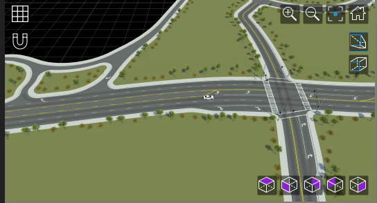
Open the scenario file TrafficSignal_SpeedReg.rrscenario.
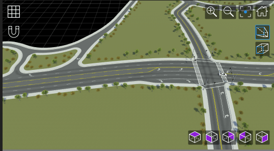
openScenario(rrApp,"TrafficSignal_SpeedReg");The scenario contains a white sedan in a lane. The path of the white sedan is laid out using waypoints and passes through the single traffic signal junction in the scene. The junction contains ten traffic signals that are converted to actors using the Traffic Signal Tool (RoadRunner Scenario).
Connect to the RoadRunner Scenario server to enable cosimulation by using the createSimulation function.
sim = createSimulation(rrApp);
Connection status: 1
Connected to RoadRunner Scenario server on localhost:60729, with client id {a58293d1-c04a-4fbf-81f0-35f1f2415edc}
Explore the Model
Open the model and load the required reference bus types into the base workspace:
modelname = "TrafficSignal_Stop"; open_system(modelname); load("rrScenarioSimTypes.mat");

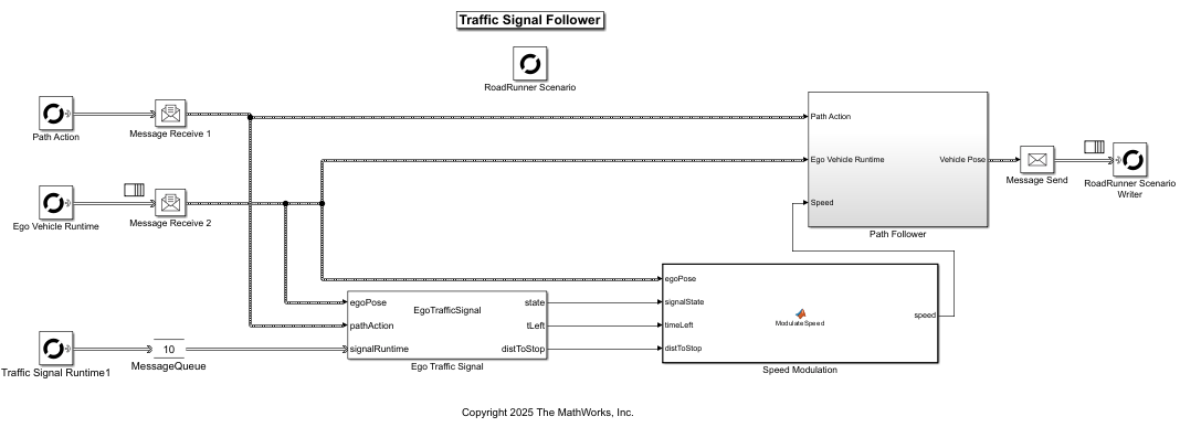
The model programs the movement of the sedan along a predefined path, and reads traffic signal information to detect changes in the signal light.
If the traffic signal is red when the sedan approaches the corresponding junction, it slows down and stops. If the traffic signal turns green for the stopped sedan, then it starts moving and accelerates until it reaches a fixed speed.
The model contains these blocks:
Ego Traffic Signal – MATLAB System Object that uses the
roadrunnerHDMapobject to check if the sedan has reached within a certain distance of the traffic signal junction. Based on this information, the System Object calculates the time left to stop and remaining distance before stopping. It also returns the state of the traffic signal.Speed Modulation – MATLAB function that controls the speed of the sedan. When the traffic signal is red, the MATLAB function calculates the necessary deceleration to slow down and stop the sedan, given that the time taken to stop is less that the time it takes for the signal to change color. When the traffic signal turns green, the function calculates the required acceleration to move the sedan forward.
Path Following – Subsystem that controls the movement of the sedan along a predefined path. The subsystem contains three MATLAB Function blocks: Vehicle Movement finds the current position vectors of the sedan along the X, Y, and Z axes, Actor Pose constructs the 4-by-4 transformation matrix representing the current pose of the sedan, and Actor Velocity constructs the velocity vector based on its yaw angle and speed.
Simulate the Scenario
Play the scenario, TrafficSignal_SpeedReg.
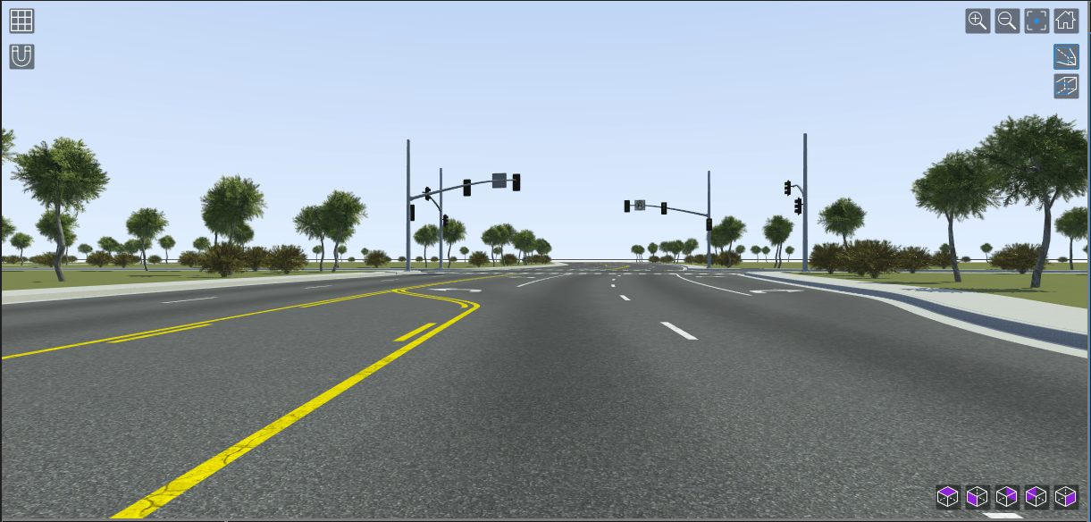
set(sim,SimulationCommand="Start");In the Simulation Tool (RoadRunner Scenario), you can change the Camera View to front to view the changing traffic signals, and the response of the car.
The sedan moves along the path towards the traffic signal junction.


The sedan stops at the junction when the traffic signal turns red. It remains stationary while the signal is red.

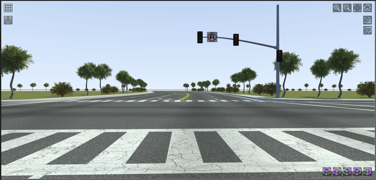
When the traffic signal turns green, the sedan starts to accelerate and move along the path again.


Extended Examples
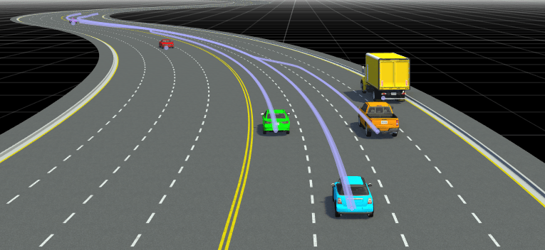
Add Sensors to RoadRunner Scenario Using Simulink
Simulate a RoadRunner Scenario with sensor models defined in Simulink and visualize object and lane detections.
Ports
Input
Specify the ID of the actor whose parent or children information you require.
To convert the ID to the uint64 data type, you can either set
the Constant value parameter of the Constant (Simulink) block to uint64(ID), where
ID is the Actor ID, or use the Data Type Conversion (Simulink) block.
Dependencies
To enable this port, set the Filter parameter to
Actor ID (provided by input).
Data Types: uint64
Output
State information from scenario, returned as a Simulink message. To extract data from the Simulink message, connect the RoadRunner Scenario Reader block to the Receive (Simulink) block.
Parameters
Topic category, specified as one of these values:
Actor— Reads the actor data from the scenarioAction— Reads the action data from the scenarioSensor— Reads the sensor data from the scenarioEvent— Reads the event data from the scenario
Type of actor in scenario, specified as All Types,
Vehicle, Traffic Signal, or Traffic
Signal Controller. The Vehicle type includes additional
wheel information of the actor.
The Traffic Signal type represents traffic signal actors, while
the Traffic Signal Controller type represents a traffic signal
controller entity that connects all traffic signal actors of a junction together.
Dependencies
To enable this parameter, set Topic Category to
Actor.
Type of action that can be read from the scenario, specified as one of these values:
| Field Name | Description |
|---|---|
Change Parameter | Reads the user-created parameter from the scenario. For more information, see Change Parameter. |
Lateral Offset | Reads the lateral offset action data from the scenario. For more information, see Lateral Offset. |
Path Following | Reads the path following action data from the scenario. For more information, see Path Following. |
Speed Change | Reads the speed change action data from the scenario. For more information, see Speed Change. |
Lane Change | Reads the lane change action data from the scenario. For more information, see Lane Change. |
Longitudinal Distance | Reads the longitudinal distance action data from the scenario. For more information, see Longitudinal Distance. |
User Defined | Reads the custom parameters of a user-defined action from the scenario. For more information, see User Defined. |
Dependencies
To enable this parameter, set Topic Category to
Action.
Sensor data derived from the scenario ground truth, specified as one of these options:
Target Poses— The block outputs poses of targets within sensor range in host vehicle coordinates. For the bus structure of the output target poses, see the output argument description of thetargetPosesfunction.Target Poses For Host— The block outputs poses of all targets in the in host vehicle coordinates. For the bus structure of the output target poses, see the output argument description of thetargetPosesfunction.Lane Boundaries— The block outputs lane boundaries within sensor range in host vehicle coordinates. For the bus structure of the output lane boundaries, see the output argument description of thelaneBoundariesfunction.Target Poses And Lane Boundaries— The block outputs both lane boundaries and poses of targets within the sensor range in host vehicle coordinates.
The origin of the host vehicle coordinates is the geometric center of the host vehicle.
You can send the above outputs directly to sensor detection generator blocks and obtain detections.
Dependencies
To enable this parameter, set Topic Category to
Sensor.
Type of event to read from a scenario.
The event being read must be mapped to the corresponding bus object in the RoadRunner Scenario block.
Dependencies
To enable this parameter, set Topic Category to
Event.
Actor data, or lane boundary captured through sensor views.
The Topic parameter can hold various sets of options, as specified in the tables below, depending on the configuration of other fields.
The Topic parameter holds the options described in the table below if both these field configurations are true:
Topic Category is set to
Actor.Actor Type is set to
All Types.
| Option | Description |
|---|---|
Actor Specifications (default) | Static attributes associated with the actor, such as actor ID, actor name, and bounding box. For more information, see Actor Specifications. |
Actor Pose | Dynamic data associated with the actor, such as pose, velocity, and angular velocity. For vehicle assets included with or created in RoadRunner, the actor origin is the geometric center of the actor. For more information, see Actor Pose. |
Actor Pose (Driving Scenario
compatible) | Dynamic data associated with the actor, such as actor ID, position, velocity, roll, pitch, yaw, and angular velocity. For vehicle assets included with or created in RoadRunner, the actor origin is the point on the ground below the center of its rear axle. For more information, see Actor Pose (Driving Scenario compatible). |
Actor Lane Location | Dynamic data associated with the lane location of actors. For more information, see Actor Lane Location. |
The Topic parameter holds the options described in the table below if both these field configurations are true:
Topic Category is set to
Actor.Actor Type is set to
Vehicle.
| Option | Description |
|---|---|
Vehicle Specifications (default) | Static attributes associated with the vehicle, such as paint color, and wheel specifications. For more information, see Vehicle Specifications. |
Vehicle Pose | Dynamic data associated with the actor, such as wheel poses. For more information, see Vehicle Pose. |
The Topic parameter holds the options described in the table below if both these field configurations are true:
Topic Category is set to
Actor.Actor Type is set to
Traffic Signal.
| Option | Description |
|---|---|
Traffic Signal Specifications
(default) | Static specifications of a traffic signal actor. For more information, see Traffic Signal Specifications Topic. |
Traffic Signal Runtime | Run-time information of a traffic signal actor. For more information, see Traffic Signal Runtime Topic. |
The Topic parameter holds the options described in the table below if both these field configurations are true:
Topic Category is set to
Actor.Actor Type is set to
Traffic Signal Controller.
| Option | Description |
|---|---|
Traffic Signal Controller Specifications
(default) | Static specifications of a traffic signal controller. For more information, see Traffic Signal Controller Specifications Topic. |
Traffic Signal Controller Runtime | Run-time information of a traffic signal controller. For more information, see Traffic Signal Controller Runtime Topic. |
The Topic parameter holds the options described in the table below if both these field configurations are true:
Topic Category is set to
Sensor.Sensor View is set to
Lane Boundaries.
| Option | Description |
|---|---|
Ego-Lane (default) | Boundaries of the lane in which the host vehicle actor is traveling |
Ego and Adjacent Lanes | Boundaries of the adjacent left and right lanes, as well as the lane in which host vehicle actor is traveling |
All Lanes | Boundaries of all lanes on the road |
Filter criteria for relevant topic data, specified as one of these options:
| Option | Description |
|---|---|
None | Output data for all actors in the scenario. When you
set Filter to
|
Self | Output data for the actor associated with the Simulink model behavior. |
Actor ID (provided by input) | Output data for a specific actor. Selecting this option exposes input port Port_1 through which you can provide an actor ID. For example, you can connect the Constant block to Port_1 to provide a fixed value that represents the ID of an actor in a scenario. |
Dependencies
To enable this parameter, set Topic Category to
Actor or Action.
Relationship to the filtered entity, specified as one of these options:
None— No selection. The RoadRunner Scenario reader block outputs data associated with the entity filtered according to the Filter parameter.Parent— Parent actor of filtered entity. The RoadRunner Scenario reader block outputs data associated with the parent of the entity filtered according to the Filter parameter.Children— Children actors of filtered entity. The RoadRunner Scenario reader block outputs data associated with the children of the entity filtered according to the Filter parameter.
For example, select Actor ID (provided by input) as the
filter to expose input port Port_1. Attach a Constant block
that outputs a value of uint64(2) to the input port. If you select
Parent from the Additional
Relationship field, then the RoadRunner Scenario Reader
block outputs data associated with the parent of the actor with ID
2.
Note
You can also use the Additional Relationship parameter to output information about actions of parent or child actors.
Dependencies
To enable this parameter, set Filter to Actor ID
(provided by input) or Self.
Unique index of the sensor, specified as a positive integer. The Sensor
ID must correspond to the Unique identifier of
sensor parameter of the corresponding sensor model detection generator
block.
Dependencies
To enable this parameter, set Topic Category to
Sensor and Sensor View to either
Target Poses, Lane Boundaries
or Target Poses And Lane Boundaries.
Sample time of simulation in seconds, specified as a positive real scalar.
Name of the user-defined event to read from a scenario.
Dependencies
To enable this parameter, set Topic Category to
Event and Event Type to
User-Defined.
More About
This table describes the output bus structure when you set Topic
Category to Action and Action
Type to Change Parameter.
| Field Name | Description |
|---|---|
Actor Action | Information about the current action of specified actor, returned as a structure. For more information, see ActorAction. |
Parameter | Information about the changed user-specified behavior parameter, returned as a structure. |
This table describes the Parameter structure.
| Field Name | Description |
|---|---|
Name | Name of the changed user-specified behavior parameter, returned as a string. |
Value | New value of the user-specified behavior parameter, returned as a string. |
ParameterType | Type of parameter. |
This table describes the output bus structure when you set Topic
Category to Action and Action
Type to Lateral Offset.
| Field Name | Description |
|---|---|
Actor Action | Information about the current action of specified actor, returned as a structure. For more information, see ActorAction. |
LateralOffsetTarget | Lateral offset relative to the current path of specified actor, returned as a structure. |
Transition Dynamics | Transition dynamics for the lateral offset change, specified as a structure. For more information, see TransitionDynamics. |
This table describes the LateralOffsetTarget structure.
| Field Name | Description |
|---|---|
OffsetValue | Target lateral offset relative to the current path, returned as a
double.
|
This table describes the output bus structure when you set Topic
Category to Action and Action
Type to Path Following.
| Field Name | Description |
|---|---|
Actor Action | Information about the current action of specified actor, returned as a structure. For more information, see ActorAction. |
PathTarget | Actor target path, returned as a structure. |
This table describes the PathTarget structure.
| Field Name | Description |
|---|---|
Path | Set of 3-D coordinates representing the target path, returned as an N-by-3 array where N = NumPoints. Each column value in the first row is the x-, y- and z- coordinate, respectively, of the first point in the target path, and so on. |
NumPoints | Total number of points on the target path, returned as a positive integer. By default, the RoadRunner Scenario Reader block can read a maximum of 500 points on the path. To change this setting, see the Configuration tab of the RoadRunner Scenario block. |
HasTimings | Indication of target path containing timing information, returned as a Boolean value. |
Timings | Timing information for each point of the path, returned as an N-by-1 structure array where N = NumPoints. |
This table describes the Timings structure array.
| Field Name | Description |
|---|---|
Time | Time of arrival of the actor at this point, relative to the time at the starting point of the path. Returned in seconds. |
Speed | Speed of actor at the time of arrival, returned in meters per second. |
WaitTime | Waiting time period of actor at arrival, returned in seconds. If this value is non-zero, then the actor is at rest. |
This table describes the output bus structure when you set Topic
Category to Action and Action
Type to Speed Change.
| Field Name | Description |
|---|---|
Actor Action | Information about the current action of specified actor, returned as a structure. For more information, see ActorAction. |
SpeedTarget | Target speed after speed change, returned as a structure. |
Transition Dynamics | Transition dynamics for the speed change, specified as a structure. For more information, see TransitionDynamics. |
This table describes the SpeedTarget structure.
| Field Name | Description |
|---|---|
SpeedValue | Target speed value, returned as a double. |
SpeedComparison | Comparison type of current speed with the target speed.
|
RefActorID | Identifier of reference actor, if any, returned as a
uint64. |
RefSamplingMode | Speed sampling mode of reference actor, if any.
|
This table describes the output bus structure when you set Topic
Category to Action and Action
Type to Lane Change.
| Field Name | Description |
|---|---|
Actor Action | Information about the current action of specified actor, returned as a structure. For more information, see Actor Action. |
LaneChangeTarget | Target lane after lane change, returned as a structure. |
Transition Dynamics | Dynamics of the transition to the lane change, returned as a structure. For more information, see TransitionDynamics. |
This table describes the LaneChangeTarget structure.
| Field Name | Description |
|---|---|
LaneValue | Number of lanes to change before reaching the target lane, returned as an
int32 value. |
LaneComparison | Direction of the lane change.
|
RefActorID | Identifier of reference actor, returned as a
uint64. |
This table describes the output bus structure when you set Topic
Category to Action and Action
Type to Longitudinal Distance.
| Field Name | Description |
|---|---|
Actor Action | Information about the current action of the specified actor, returned as a structure. For more information, see Actor Action. |
DistanceTarget | Information about the longitudinal distance to the reference actor, returned as a structure. |
ReferenceSamplingMode | Phase interval at which the target longitudinal distance is achieved.
|
DynamicConstraints | Dynamic constraints for the longitudinal distance change, returned as a structure. |
This table describes the DistanceTarget structure.
| Field Name | Description |
|---|---|
RefActorID | Identifier of reference actor, returned as a
uint64. |
DistanceDimensionType | Type of distance to reference actor.
|
DistanceType | Specification of longitudinal distance as either time distance or space distance.
|
ActorCoordinateSystemType | Coordinate system in which to measure required longitudinal distance.
|
Value | Longitudinal distance, returned as a double. |
PositionComparison | Relative position to reference actor.
|
MeasureFrom | Longitudinal distance is either measured between the closest points on two actors' bounding boxes or between the origin point of both actors.
|
This table describes the DynamicConstraints structure.
| Field Name | Description |
|---|---|
UnlimitedDynamics | Presence of dynamic constraints, returned as a Boolean value. |
MaxSpeed | Maximum speed that an actor can attain while approaching target longitudinal
distance to reference actor, returned as a double. |
MaxAcceleration | Maximum acceleration that an actor can attain while approaching target
longitudinal distance to reference actor, returned as a
double. |
MaxDeceleration | Maximum deceleration that an actor can attain while approaching target
longitudinal distance to reference actor, returned as a
double. |
This table describes the output bus structure when you set Topic
Category to Action and Action
Type to UserDefined.
| Field Name | Description |
|---|---|
Actor Action | Information about the current action of specified actor, returned as a structure. For more information, see Actor Action. |
Name | Action name, returned as a string. |
Parameters | Custom parameters of the user-defined action, returned as a structure. This structure contains the name and value for each custom parameter. |
The ActorAction structure is the same for all action types. This
table describes the ActorAction structure.
| Field Name | Description |
|---|---|
ActionID | Identifier of the actor action, returned as a
|
ActorID | Identifier of actor performing the action, returned as a
|
PhaseInterval | Phase interval to which the action is applied.
|
ActionTypes | Action type.
|
This table describes the TransitionDynamics structure.
| Field Name | Description |
|---|---|
Dimension | Transition metric measuring the action change.
|
Shape | Shape of the transition curve.
|
Value | Value of the chosen transition metric, returned as a
double. |
This table describes the output bus structure when you set Topic
Category to Actor, Actor Type
to All Types and Topic to Actor
Specifications.
| Field Name | Description |
|---|---|
ActorID | Actor identifier, returned as a
|
ActorName | Actor name, returned as a string. |
BoundingBox | Bounding box of the actor, returned as a structure. |
This table describes the BoundingBox structure.
| Field Name | Description |
|---|---|
Min | The bounding box corner with minimal x-, y- and z- values, returned as a 1-by-3 array. |
Max | The bounding box corner with maximal x-, y- and z- values, returned as a 1-by-3 array. |
This table describes the output bus structure when you set Topic
Category to Actor, Actor Type
to All Types and Topic to Actor
Pose.
| Field Name | Description |
|---|---|
ActorID | Scenario-defined actor identifier, returned as a
uint64. |
Pose | Position and orientation of the actor, returned as a 4-by-4 array. See What Is a RoadRunner Pose Matrix? |
Velocity | Actor velocity, in meters per second, in the x-, y-and z- directions, returned as a 1-by-3 vector. |
AngularVelocity | Angular velocity, in radians per second, of actor in the x-, y-and z- directions, returned as a 1-by-3 vector. |
This table describes the output bus structure when you set Topic
Category to Actor, Actor Type
to All Types and Topic to Actor
Pose(Driving Scenario compatible).
| Field Name | Description |
|---|---|
ActorID | Scenario-defined actor identifier, returned as a
uint64. |
Position | Position of actor, returned as a real-valued vector of the form [x y z]. Units are in meters. |
Velocity | Velocity (v) of actor in the x- y-, and z-directions, returned as a real-valued vector of the form [vx vy vz]. Units are in meters per second. |
Roll | Roll angle of actor, returned as a real-valued scalar. Units are in degrees. |
Pitch | Pitch angle of actor, returned as a real-valued scalar. Units are in degrees. |
Yaw | Yaw angle of actor, returned as a real-valued scalar. Units are in degrees. |
AngularVelocity | Angular velocity (ω) of actor in the x-, y-, and z-directions, returned as a real-valued vector of the form [ωx ωy ωz]. Units are in degrees per second. |
This table describes the output bus structure when you set Topic
Category to Actor, Actor Type
to All Types, and Topic to
Actor Lane Location.
| Field Name | Description |
|---|---|
ActorID | Scenario-defined actor identifier, returned as a
uint64. |
IsOnLane | Boolean value indicating if the actor is located on a lane. An actor is considered to be on a certain lane if its model origin lies in between the left and right boundaries of this lane. |
LocationOnLane | Current lane of actor, returned as a structure. If an actor straddles several lanes, the most aligned lane is returned. |
This table describes the LocationOnLane structure.
| Field Name | Description |
|---|---|
LaneID | UUID identifier of the most aligned lane, returned as a string. |
Position | Position of the actor on the lane-center polyline (in s-value). The s-value is a double value within [0, 1] that indicates a position on a 3-D polyline with 0 at the start and 1 at the end of the polyline. |
Angle | Angle between the actor travel direction and tangent at the lane position. Units are in radians. |
You can use the RoadRunner Scenario Reader block to access
the lane location of all the actors in your simulation by setting
Filter to None. In this case, the block
outputs a message associated with each actor and each message has a field for actor ID. You
can use a Queue (Simulink) block to store and queue messages. See
Filter.
This table describes the output bus structure when you set Topic
Category to Actor, Actor Type
to Vehicle and Topic to Vehicle
Specifications.
| Field Name | Description |
|---|---|
ActorSpec | Actor specifications, returned as a structure. |
PaintColor | Color of the actor, returned as a structure. |
NumWheels | Number of wheels, returned as a |
Wheels | Wheel specifications of vehicle-type actor, returned as a structure. |
This table describes the ActorSpec structure.
| Field Name | Description |
|---|---|
ActorID | Actor identifier, returned as a
|
ActorName | Actor name, returned as a string. |
BoundingBox | Bounding box of the actor, returned as a structure. |
Note
The ActorSpec structure is also returned when you set
Topic Category to Actor, Actor
Type to All Types and Topic
to Actor Specifications.
This table describes the PaintColor structure.
| Field Name | Description |
|---|---|
r | Red color, returned as a uint32 value. |
g | Green color, returned as a uint32 value. |
b | Blue color, returned as a uint32 value. |
a | Transparency of the color (alpha), returned as a uint32
value. |
This table describes the Wheels structure.
| Field Name | Description |
|---|---|
AxleIndex | Axle index of a wheel. The front-most axle has the starting index value of
zero, with index values increasing towards the vehicle rear. Returned as a
uint32 value. |
WheelOffset | x-, y- and z- coordinates of the wheel center, in the vehicle coordinate system. Returned as a 1-by-3 vector. |
WheelRadius | Radius of the wheel in meters. Returned as a double. |
This table describes the output bus structure when you set Topic
Category to Actor, Actor Type
to Vehicle and Topic to Vehicle
Pose.
| Field Name | Description |
|---|---|
ActorRuntime | Actor runtime values, returned as a structure. |
NumWheels | Number of wheels, returned as a uint32 value. |
WheelPoses | Runtime pose of each wheel of vehicle-type actor, returned as a multidimensional 4-by-4-by-N array. N is the number of wheels of the vehicle-type actor.
|
This table describes the ActorRuntime structure.
| Field Name | Description |
|---|---|
ActorID | Scenario-defined actor identifier, returned as a
uint64. |
Pose | Position and orientation of the actor, returned as a 4-by-4 array. See What Is a RoadRunner Pose Matrix? for more information. |
Velocity | Actor velocity, in meters per second, in the x-, y-and z- directions, returned as a 1-by-3 vector. |
AngularVelocity | Angular velocity, in radians per second, of actor in the x-, y-and z- directions, returned as a 1-by-3 vector. |
Note
The ActorRuntime structure is also returned when you set
Topic Category to Actor, Actor
Type to All Types and Topic
to Actor Pose.
This table describes the output bus structure when you set Topic
Category to Actor, Actor Type
to Traffic Signal and Topic to
Traffic Signal Runtime.
| Field Name | Description |
|---|---|
SignalHead | Signal head specifications, returned as a structure of type
|
SignalConfiguration | Information about the current configuration of the specified traffic
signal, returned as a structure of type
|
This table describes the fields of the SignalHead structure:
| Field Name | Description |
|---|---|
SignalID | UUID of traffic signal, returned first as a To convert the row vector into its alphanumeric form, use the char function, which returns the UUID as a character array. |
ControllerID | UUID of traffic signal controller, returned first as a
To convert the row vector into its alphanumeric form, use the char function, which returns the UUID as a character array. |
This table describes the fields of the SignalConfiguration structure:
| Field Name | Description |
|---|---|
ConfigurationIndex | Current configuration index of the specified traffic signal, returned
as a Configuration index indicates the overall configuration of a traffic signal. For example, if the red bulb of a traffic signal is in the "On" state, and the green and yellow bulbs are "Off", then the traffic signal is red. A certain configuration index is assigned to every such possible configuration. |
NumBulbConfiguration | Number of bulb configurations for the specified signal, returned as a
|
BulbConfiguration | Bulb name and state for all bulbs of the specified traffic signal,
returned as a structure array of type
|
NumTurnConfiguration | Number of turn configurations for the specified traffic signal,
returned as a |
TurnConfiguration | Turn configuration information for the specified traffic signal,
returned as a structure array of type
|
This table describes the fields of the BulbConfiguration structure array:
| Field Name | Description |
|---|---|
BulbName | Name of the bulb, returned first as a This field corresponds to the Node Name of the bulb as seen in the RoadRunner application. To obtain a readable word, you must
convert the |
BulbState | State of signal bulb, returned as an enumeration variable. Possible values of the variable are:
|
This table describes the fields of the TurnConfiguration structure array:
| Field Name | Description |
|---|---|
TimeLeft | Time remaining for the completion of the current turn type, returned as
a |
TurnType | Possible turn types:
Every turn type has a corresponding configuration type (maneuver signalization); together, this information (called turn state) determines the allowed turns at a traffic signal. |
ConfigurationType | Maneuver signalization at specified traffic signal, returned as an enumeration variable. The value of the variable can be:
A configuration type (maneuver signalization) is assigned to every turn type; together, this information (turn state) determines the allowed turns at a traffic signal. |
This table describes the output bus structure when you set Topic
Category to Actor, Actor Type
to Traffic Signal Controller and Topic to
Traffic Signal Controller Runtime.
| Field Name | Description |
|---|---|
ControllerID | UUID of traffic signal controller, returned first as a
To convert the row vector into its alphanumeric form, use the char function, which returns the UUID as a character array. |
SignalPhase | Information about current signal phase, returned as a structure of type
|
SignalInterval | Information about the current signal phase interval, returned as a
structure of type |
PhaseTime | Information about phase timings, returned as a structure of type
|
CycleTime | Information about cycle timings, returned as a structure of type
A cycle comprises of all signal phases, taken together. |
ControllerStatus | Status of traffic signal controller, returned as an enumeration variable. Possible values of the variable are:
|
This table describes the fields of the SignalPhase structure:
| Field Name | Description |
|---|---|
PhaseName | Name of the current phase, returned first as a To obtain a readable word, you must convert the
|
PhaseNumber | Number assigned to current signal phase based on its order, returned as
a |
This table describes the fields of the SignalInterval structure:
| Field Name | Description |
|---|---|
IntervalName | Name of the current interval within a signal phase, returned first as a
To obtain a readable word,
you must convert the |
IntervalType | Interval type, informing about allowed turn types at a junction, returned as an enumeration variable. The value of the variable can be:
This field corresponds to the Interval Type of a phase interval, as seen in the RoadRunner application. |
This table describes the fields of the PhaseTime structure:
| Field Name | Description |
|---|---|
Duration | Total time spent in a signal phase, returned as a
|
TimeLeft | Time left in a signal phase, returned as a
|
This table describes the fields of the CycleTime structure:
| Field Name | Description |
|---|---|
Duration | Total time spent in a cycle, returned as a |
TimeLeft | Time left in a cycle, returned as a
|
This table describes the output bus structure when you set Topic
Category to Actor, Actor Type
to Traffic Signal and Topic to
Traffic Signal Specifications.
| Field Name | Description |
|---|---|
SignalHead | Signal head specifications, returned as a structure of type
|
SignalPosition | World coordinates of the point of attachment of a signal head to a traffic signal pole, returned as a 1-by-3 double array. |
SignalStatus | Status of a traffic signal, returned as an enumeration variable. The value of the variable can be:
|
NumSignalPhaseState | Number of signal phases for a traffic signal, returned as a
|
SignalPhaseState | Information about each signal phase, returned as a structure array of
type For more information about signal phases, see the Signal Tool (RoadRunner). |
NumSupportedTurnTypes | Number of turn types supported by a traffic signal, returned as a
|
SupportedTurnTypes | Supported turn types, returned as an enumeration array, with the following possible values:
|
NumBulbConfigurations | Number of signal bulb configurations for the specified traffic signal,
returned as a |
BulbConfigurations | Configuration information about signal bulbs, returned as a structure
array of type |
NumTurnConfigurations | Number of turn configurations for the specified traffic signal,
returned as a |
TurnConfigurations | Turn configuration information for a traffic signal, returned as a
structure array of type |
This table describes the fields of the SignalHead structure:
| Field Name | Description |
|---|---|
SignalID | Universal unique identifier (UUID) of traffic signal, returned first as
a To convert the row vector into its alphanumeric form, use the char function, which returns the UUID as a character array. |
ControllerID | UUID of traffic signal controller, returned first as a
To convert the row vector into its alphanumeric form, use the char function, which returns the UUID as a character array. |
This table describes the fields of the SignalPhaseState structure array:
| Field Name | Description |
|---|---|
NumConfigurationIndex | Number of intervals in a phase, returned as a |
ConfigurationIndex | Configuration index of traffic signal in each interval of a signal
phase, returned as a The configuration index indicates the configuration of a traffic signal. For example, if the red bulb of a traffic signal is in the "On" state, and the green and yellow bulbs are "Off", then the traffic signal is red. A certain configuration index is assigned to every such possible configuration. |
This table describes the fields of the BulbConfigurations structure array:
| Field Name | Description |
|---|---|
ConfigurationNumber | Configuration number of traffic signal, returned as a
This field corresponds to the
|
NumBulbConfiguration | Number of bulb configurations for the specified signal, returned as a
|
BulbConfiguration | Bulb name and state, returned as a structure array of type
|
This table describes the fields of the BulbConfiguration structure array:
| Field Name | Description |
|---|---|
BulbName | Name of the bulb, returned first as a This field corresponds to the Node Name of the bulb as seen in the RoadRunner application. To obtain a readable word, you must
convert the |
BulbState | State of signal bulb, returned as an enumeration variable. Possible values of the variable are:
|
This table describes the fields of the TurnCofigurations structure array:
| Field Name | Description |
|---|---|
ConfigurationNumber | Configuration number of traffic signal, returned as a
This field corresponds to the
|
NumTurnState | Total number of turn states, returned as a |
TurnState | Turn type in combination with configuration type (maneuver
signalization), returned as a structure array of type
For more information about maneuver signalization, see the Maneuver Tool (RoadRunner). |
This table describes the fields of the TurnState structure array:
| Field Name | Description |
|---|---|
TurnType | Turn types, returned as an enumeration variable. Possible values of the variable are:
Every turn type has a corresponding configuration type (maneuver signalization). The turn type and configuration type together comprise a turn state, which determines the allowed turns at a traffic signal. |
ConfigurationType | Maneuver signalization, returned as an enumeration variable. The value of the variable can be:
A configuration type (maneuver signalization) is assigned to every turn type. The configuration type and turn type together comprise a turn state, which determines the allowed turns at a traffic signal. |
This table describes the output bus structure when you set Topic
Category to Actor, Actor Type
to Traffic Signal Controller and Topic to
Traffic Signal Controller Specifications.
| Field Name | Description |
|---|---|
ControllerID | UUID of traffic signal controller, returned first as a
To convert the row vector into its alphanumeric form, use the char function, which returns the UUID as a character array. |
NumTrafficSignalControllerPhases | Number of phases, returned as a |
TrafficSignalControllerPhases | Information about the phases of a traffic signal controller, returned
as a structure array of type |
This table describes the fields of the TrafficSignalControllerPhase
structure array:
| Field Name | Description |
|---|---|
PhaseName | Name of the phase, returned first as a To obtain a readable word, you must convert the
|
NumPhaseInterval | Number of intervals in the phase, returned as a
|
PhaseInterval | Information about the phase interval, returned as a
1-by-n structure array of type
|
This table describes the fields of the PhaseInterval structure array:
| Field Name | Description |
|---|---|
IntervalName | Name of the interval, returned first as a To obtain a readable word, you must convert the
|
IntervalType | Interval type, informing about allowed turn types at a junction, returned as an enumeration variable. The value of the variable can be:
This field corresponds to the Interval Type of a phase interval, as seen in the RoadRunner application. |
IntervalTime | Time duration of an interval, returned as a
|
Version History
Introduced in R2022aGet traffic signal and traffic signal controller information by setting the
Topic Category parameter to Actor, and
Actor Type to Traffic Signal or
Traffic Signal Controller.
You can then output the static or run-time specifications of the specified traffic signal or traffic signal controller by changing the Topic parameter.
Get actor or action information associated with the parent or children actors of a
specific actor by setting the Topic Category parameter to
Actor or Action, and
Filter to Actor ID (provided by input).
Setting these parameter values exposes the input port Port_1. Depending on your
requirement, set the Additional Relationship parameter to
Parent or Children.
Starting in R2023a, MapLocation and its bus definition
BusVehicleMaplocation are not supported, when you access
Vehicle Pose using a RoadRunner Scenario Reader block.
To read an actor location, use the new dedicated topic Actor Lane
Location. The change allows you to access location data associated with any
actor in your RoadRunner Scenario simulation.
See Also
RoadRunner Scenario | RoadRunner Scenario Writer | Receive (Simulink)
MATLAB Command
You clicked a link that corresponds to this MATLAB command:
Run the command by entering it in the MATLAB Command Window. Web browsers do not support MATLAB commands.
Web サイトの選択
Web サイトを選択すると、翻訳されたコンテンツにアクセスし、地域のイベントやサービスを確認できます。現在の位置情報に基づき、次のサイトの選択を推奨します:
また、以下のリストから Web サイトを選択することもできます。
最適なサイトパフォーマンスの取得方法
中国のサイト (中国語または英語) を選択することで、最適なサイトパフォーマンスが得られます。その他の国の MathWorks のサイトは、お客様の地域からのアクセスが最適化されていません。
南北アメリカ
- América Latina (Español)
- Canada (English)
- United States (English)
ヨーロッパ
- Belgium (English)
- Denmark (English)
- Deutschland (Deutsch)
- España (Español)
- Finland (English)
- France (Français)
- Ireland (English)
- Italia (Italiano)
- Luxembourg (English)
- Netherlands (English)
- Norway (English)
- Österreich (Deutsch)
- Portugal (English)
- Sweden (English)
- Switzerland
- United Kingdom (English)

