Service Interfaces Overview
When your applications or software components need to communicate with each other through a functional interface, use service-oriented communication where services are provided and requested by different components depending on the target platform. You can use service-oriented architectures to decide the implementation of a function in your component after deployment. A service-oriented architecture allows you to think about your components as micro-services that enable powerful capabilities such as over-the-air updates and cloud functionality. System Composer™ allows you to model these scenarios using service interfaces.
You can model your service-oriented communication at the architecture level using software architectures in System Composer. Starting at the architecture level allows you to design your service interface and components independent of the implementation of their behavior. Ports and interfaces in an architecture describe 'what' the system should do and implementation of behavior in linked Simulink® models describe 'how' the component should do it.
If you start from the architecture level, you can use these methods to define Simulink behavior for your components:
Use a preconfigured Simulink template.
System Composer can provide you with preconfigured Simulink model.
Manually model your behavior in Simulink and link the model to your software architecture components. For more information, see Model Client and Server Components Using Function Ports.
This topic shows how to model service-oriented communication starting from a System Composer software architecture and implementing component behavior with Simulink.
Structure of Service-Oriented Architectures

A service-oriented architecture consists of these elements:
A software component is a specialization of a component for software entities, including its interfaces.
A server is a component that defines and provides a function.
A client is a component that sends a request to the server.
A service interface defines the functional interface between client and server components. Each service interface consists of one or more function elements.
A service is a unit of functionality.
A function element describes the attributes of a function in a client-server interface.
Clients and servers are often used to distribute functionality across a distributed system or to access services offered by cloud APIs. Therefore, calling a service may require resources and you may want to specify if the execution should be synchronous or asynchronous.
Synchronous execution is when the client sends a request to the server, the function runs immediately, and the function returns the output arguments to the client.
Asynchronous execution is when the client sends a request to the server, the function executes asynchronously based on the priority order, and the function returns the output arguments to the client.
Author Service Interfaces Using System Composer
In System Composer, to connect your client and server components, use client and server ports.

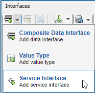
After you connect the client and server components, you can specify function elements by creating a service interface. To create a service interface, open the Interface Editor, click the down arrow, and select Service Interface.
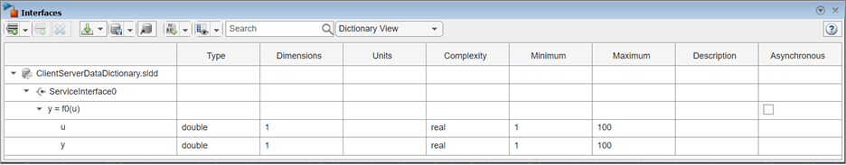
You can create functions in your software architecture using the Interface
Editor. For each function in the service interface, add a function
element. Specify if the function is asynchronous by selecting the
Asynchronous check box. To define the name and parameters
of the function, edit the function prototype. Below the function prototype are the
parameters of the function represented as function arguments. For each function
argument, you can specify values in the Type,
Dimensions, Units,
Complexity, and Asynchronous columns.
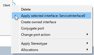
After you define and select a service interface, you can assign the interface to client and server ports in your architecture by right-clicking the port and selecting Apply selected interface.
Describe Client-Server Interactions Using Sequence Diagrams
Since R2024b
You can use sequence diagrams with System Composer to describe interactions between client and server components. While designing your service-oriented architecture, use sequence diagrams to represent component interactions, which consist of sequences of call and response messages. In sequence diagrams, a client component sends a request through a call message to a server component. In exchange, the server component returns a response message to the client component.

For more information about sequence diagram concepts, see Describe System Behavior Using Sequence Diagrams.
Author Call and Response Messages Between Client and Server Components
Create a sequence diagram to specify expected interactions between components based on the service interface, functions, and function arguments that you specified in the Interface Editor.
In the Diagrams section of the Modeling tab in the System Composer toolstrip, click Sequence Diagram.
In the Architecture Views Gallery, select New > Sequence Diagram.
From the Model Browser, drag architecture components onto the canvas to create lifelines.
Draw a line from one lifeline to another to create a message.
To author a call message from a client to a server, click the Create a call message from client port to server port
 button. In the
To field, select or type the name of the
server port and in the From field, select or
type the name of the client port. Call messages are represented by a
solid line with a solid arrowhead.
button. In the
To field, select or type the name of the
server port and in the From field, select or
type the name of the client port. Call messages are represented by a
solid line with a solid arrowhead.To author a response message from a server to a client, click the Create a response message from server port to client port
 button. In the
To field, select or type the name of the
client port and in the From field, select or
type the name of the server port. Response messages are represented
by a dashed line with a line arrowhead.
button. In the
To field, select or type the name of the
client port and in the From field, select or
type the name of the server port. Response messages are represented
by a dashed line with a line arrowhead.Use message labels to describe component interactions. A message label has a trigger, an optional guard, and an optional constraint in the form of
trigger[guard]{constraint}. In call and response messages:The
triggerspecifies the name of a function and represents the arrival of a request from the client or a return from the server in call and response messages, respectively.The
guardis a Boolean expression to determine whether the message occurs. Evaluation of the guard only occurs once a valid trigger has been detected.The
constraintis a Boolean expression that includes input signals of the source component and function arguments.
Guard and constraint expressions of a call message can include the input arguments of the function and any input signals of the client component. Similarly, guard and constraint expressions in a response message can include the input and output arguments of the function and any input signals of the server component.
Implement Behavior of Functions Using Simulink
To implement behaviors for your functions, you can create Simulink behavior models.
To define and implement the behavior of:
Your server component, use a Simulink export-function model. For more information about export-function models, see Export-Function Models Overview.
Your client component, use either a Simulink rate-based model or export-function model.
Note
Rate-based behavior models are supported when implementing a call to a synchronous service. (since R2024b)
When implementing a call to an asynchronous service, you must use an export-function behavior model.
To create a Simulink behavior, right-click the component and select Create a
Simulink behavior and set the Type of the
Simulink behavior to either Model Reference:
Rate-Based or Model Reference:
Export-Function.

The created model is a template model that includes the service interface you created in System Composer. In your software architecture, you see the model as a model reference in the component. The implementation of the behavior depends on the synchronicity of the function execution.
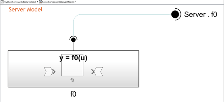
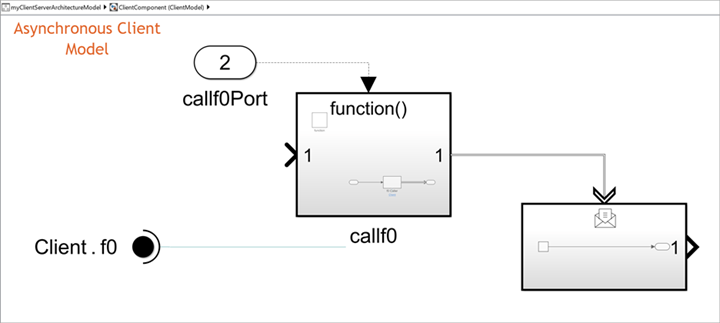
You can define your service in the server model by implementing the desired algorithm of your service inside of the Simulink Function block. Add any necessary blocks to the Simulink Function block and ensure these blocks are connected to the argument blocks. ArgIn and ArgOut blocks represent the function input and output arguments, respectively.
You can call your service in the client model by implementing the function call inside of the Function-Call Subsystem block. Add any necessary blocks to the function call subsystem to represent any inputs and outputs. For asynchronous execution, the output message is a message payload.
For more information about implementing function behavior, see Model Client and Server Components Using Function Ports.
Simulate Your Service Using System Composer
You can simulate service-oriented communication by compiling and running your service-oriented architecture model.
To run your architecture model, click the Run button or use
the sim function. For example, if your
model is called myServiceModel, enter this command to run your
model:
sim('myServiceModel')After the model simulates, you can analyze and visualize signals using the Simulation Data Inspector and Sequence Viewer tools.
To visualize the logged signals, go to the Simulation tab, and in the Review Results section, select Simulation Data Inspector.
To view the execution order of the function calls, go to the Simulation tab, and in the Review Results section, select Sequence Viewer.
You can modify the execution order of functions in your service interface from the Functions Editor.
For more information, see Model Service-Oriented Communication Between Sensors.
Test Your Service Interface Using Simulink Test
Since R2024a
To test service interfaces, you can create a test harness for architectures and components with client and server ports. A Simulink Test™ license is required to create a test harness. A test harness is a model that allows you to test a model or model component in an environment separate from the original model.
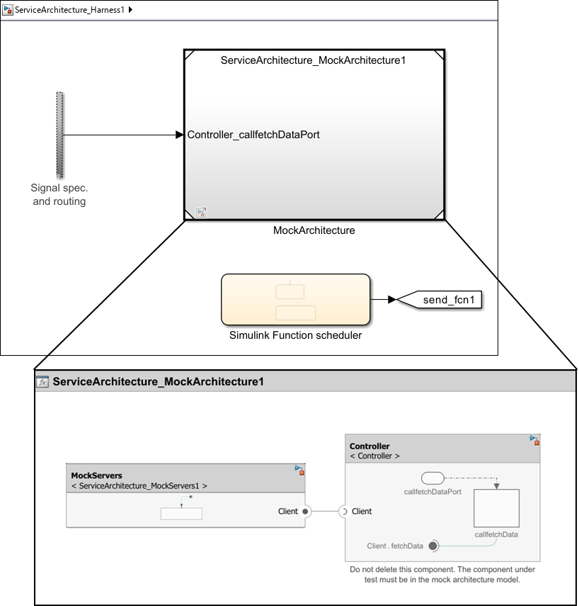
When you create a test harness, Simulink Test generates a test harness model and a mock architecture model.
The test harness model provides a model to configure testing scenarios by specifying inputs and outputs, and test cases in scheduler blocks.
The mock architecture model contains mock components for implementation of client or server components communicating with your component under test.
In this example, a test harness is created for a component,
Controller, which has a client port.
ServiceArchitecture_Harness1is the test harness model.ServiceArchitecture_MockArchitecture1is the mock architecture model.ServiceArchitecture_MockServers1is the additional mock component connected to the client port of the component under test, enabling simulation of the service interface.
To create a test harness, right-click in an architecture or component, click
Test Harness, and select
Create. Alternatively, use the sltest.harness.create (Simulink Test)
function.
For an example, see Model Service-Oriented Communication Between Sensors.
Generate Code Using Embedded Coder
An Embedded Coder® license is required to generate code.
You can generate code from the software architecture model for each component. The generated code contains an entry-point for each function of the component. To generate code, on the Apps tab, select Embedded Coder. On the C Code tab, in the Generate Code section, select Generate Code.
See Also
Blocks
- Function Element | Function Element Call | Simulink Function | Function Caller | Function-Call Subsystem | Message Triggered Subsystem | Reference Component