Spherical Joint
Joint allows 3-D rotations

Libraries:
Simscape /
Multibody /
Joints
Description
The Spherical Joint block provides three rotational degrees of freedom between two frames. The follower frame can have an arbitrary 3-D rotation with respect to the base frame. During a simulation, the origins of the base and follower frames remain coincident, as shown in the image.
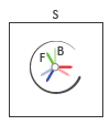
Unlike a gimbal joint, the Spherical Joint does not have kinematic singularity.
To specify the target of the initial state for a joint primitive, use the parameters under State Targets. The targets are specified in the base frame. You can also set the priority levels for the targets. If the joint is not able to satisfy all the state targets, the priority level determines which targets to satisfy first and how closely to satisfy them. For an example, see the Guiding Assembly section of How Multibody Assembly Works.
To model damping and the spring behavior for a joint primitive, use the parameters under Internal Mechanics. Use the Damping Coefficient parameter to model energy dissipation and the Spring Stiffness parameter to model energy storage. Joint springs attempt to displace the joint primitive from its equilibrium position, and joint dampers act as energy dissipation elements. The springs and dampers are strictly linear.
To specify the limits of a joint primitive, use the parameters under Limits. The lower and upper bounds define the width of the free region. The block applies a force to accelerate the joint position back to the free region when the position exceeds the bounds. The block uses a smoothed spring-damper method to compute the force. For more information about the smoothed spring-damper method, see the Description section of the Spatial Contact Force block.
The Force, Torque, and Motion parameters in the Actuation section control the motion of the joint primitives during simulation. For more information, see Specifying Joint Actuation Inputs. Additionally, the joint block has ports that output sensing data, such as position, velocity, acceleration, force, and torque, that you can use to perform analytical tasks on a model. For more information, see Sensing and Force and Torque Sensing.
To specify the joint mode configuration, use the Mode parameter. For more details, see Mode Configuration under the Ports and Parameters sections.
Faults
Using mode faults, you can change the joint modes during a simulation without modifying the
model design. The fault injection overrides the mode setting. For example, if a joint has
the Mode parameter set to Locked and the
Fault behavior parameter set to Disengaged, the
joint becomes disengaged.
To add a mode fault to a joint block, click on the joint block, in the Simscape Block tab, and the Faults section,
click Fault > Add Fault.
Alternatively, you can click the joint block, hover over the ellipsis to open the action
bar, and click the Add a fault on the block icon ![]() . You can add multiple faults to a joint block, but the
joint block can have only one active fault during a simulation.
. You can add multiple faults to a joint block, but the
joint block can have only one active fault during a simulation.
As you add faults, in the Property Inspector, under the Fault
section, specify the behavior and the trigger type of the fault. To define the fault
behavior, click the link next to the Fault Behavior. This
joint supports Locked, Normal, or
Disengaged mode. The joint blocks support these trigger types:
Always on, Timed, Manual, and
Conditional. For more details of these trigger types, see Set Fault Triggers. To trigger a
conditional fault, you can use Simulink signals, Simscape language blocks, and MATLAB
workspace variables. To set the active fault for a block, use the Fault Table. For more
details, see Access the Fault Table and Fault Dashboard.
To enable fault simulation, in the Simscape Block tab and
the Faults section, turn on the Fault
Simulation button. The fault simulation is on when the button is green and
the status is on. The simulation logs the trigger status
data. To view the data, use the Simulation Data
Inspector. Also, you can see the fault status and a summary of the triggered
faults in the Fault Dashboard. To open the Fault Dashboard, in the Simscape Block tab, click Faults >
Fault Dashboard.
To create and modify faults, you can also use Simscape™ and Simulink® fault functions. For more details, see the function section of the Simulink Fault Controls and Simscape Faults Interface.
Examples
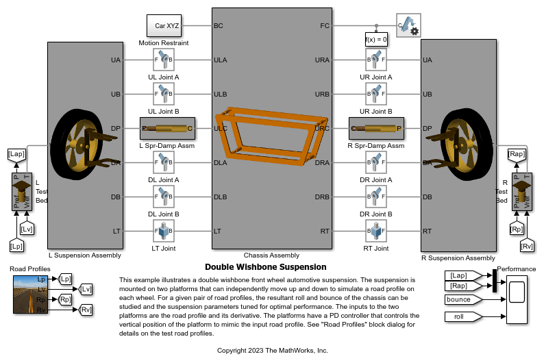
Double Wishbone Suspension
Illustrates a double wishbone front wheel automotive suspension. The suspension is mounted on two platforms that can independently move up and down to simulate a road profile on each wheel. For a given pair of road profiles, the resultant roll and bounce of the chassis can be studied and the suspension parameters tuned for optimal performance. The inputs to the two platforms are the road profile and its derivative. The platforms have a PD controller that controls the vertical position of the platform to mimic the input road profile. See "Road Profiles Generator" block dialog box for details on the test road profiles.
Ports
Frame
Input
Output
Spherical Primitive (S)
Orientation of the follower frame with respect to the base frame, returned as a unit quaternion. See Quaternion Measurements for more information.
Dependencies
To enable this port, under Spherical Primitive (S) > Sensing, select Position.
x-coordinate of the relative angular velocity, returned as a scalar. The value is resolved in the resolution frame.
Dependencies
To enable this port, under Spherical Primitive (S) > Sensing, select Velocity (X).
y-coordinate of the relative angular velocity, returned as a scalar. The value is resolved in the resolution frame.
Dependencies
To enable this port, under Spherical Primitive (S) > Sensing, select Velocity (Y).
z-coordinate of the relative angular velocity, returned as a scalar. The value is resolved in the resolution frame.
Dependencies
To enable this port, under Spherical Primitive (S) > Sensing, select Velocity (Z).
Relative angular velocity, returned as a 3-D vector resolved in the resolution frame.
Dependencies
To enable this port, under Spherical Primitive (S) > Sensing, select Velocity.
x-coordinate of the relative angular acceleration, returned as a scalar. This quantity equals the time derivative of the signal exported from the port wx.
Dependencies
To enable this port, under Spherical Primitive (S) > Sensing, select Acceleration (X).
y-coordinate of the relative angular acceleration, returned as a scalar. This quantity equals the time derivative of the signal exported from the port wy.
Dependencies
To enable this port, under Spherical Primitive (S) > Sensing, select Acceleration (Y).
z-coordinate of the relative angular acceleration, returned as a scalar. This quantity equals the time derivative of the signal exported from the port wz.
Dependencies
To enable this port, under Spherical Primitive (S) > Sensing, select Acceleration (Z).
Relative angular acceleration, returned as a 3-D vector resolved in the resolution frame. This quantity equals the time derivative of the signal exported from the port w.
Dependencies
To enable this port, under Spherical Primitive (S) > Sensing, select Acceleration.
Physical signal port that outputs the magnitude of the lower-limit torque. The block applies the lower-limit torque when the angle between the z-axes of the two frames is less than the bound of the lower limit. The torque applies to both the base and follower frames of the spherical primitive to accelerate the relative position back to the free region.
Dependencies
To enable this port, under Spherical Primitive (S) > Sensing, select Signed Lower-Limit Torque Magnitude.
Physical signal port that outputs the magnitude of the upper-limit torque. The block applies the upper-limit torque when the angle between the z-axes of the two frames exceeds the upper bound. The torque applies to both the base and follower frames of the spherical primitive to accelerate the relative position back to the free region.
Dependencies
To enable this port, under Spherical Primitive (S) > Sensing, select Upper-Limit Torque.
Composite Force/Torque Sensing
Physical signal port that outputs the constraint forces that act across the joint.
These forces maintain the translational constraints of the joint. The output has a
3-by-1 vector format and represents the force components along the
x, y, and z axes of the
resolution frame. For more information, see Force and Torque Sensing.
Dependencies
To enable this port, under Composite Force/Torque Sensing, select Constraint Force.
Physical signal port that outputs the constraint torques that act across the
joint. These torques maintain the rotational constraints of the joint. The output
has a 3-by-1 vector format and represents the torque components about the
x, y, and z axes of the
resolution frame.
Dependencies
To enable this port, under Composite Force/Torque Sensing, select Constraint Torque.
Physical signal port that outputs the total force that acts across the joint. The
total force is the sum of the of all forces transmitted between the connected frames
through the joint. The output has a 3-by-1 vector format and represents the force
components along the x, y, and
z axes of the resolution frame.
To demonstrate the total force acting on a joint, the figure shows a model using a Prismatic Joint block.
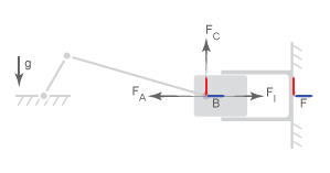
The total force includes the actuator force (FA), internal force (FI), and constraint forces (FC). For more information, see Force and Torque Sensing.
Dependencies
To enable this port, under Composite Force/Torque Sensing, select Total Force.
Physical signal port that outputs the total torque that acts across the joint. The
total torque is the sum of all torques transmitted between the connected frames
through the joint. The torque includes the actuation, internal, limit, and
constraint torques. The output has a 3-by-1 vector format and represents the torque
components about the x, y, and
z axes of the resolution frame. For more information, see
Force and Torque Sensing.
Dependencies
To enable this port, under Composite Force/Torque Sensing, select Total Torque.