surfaceReflectivityLand
Description
This System object™ creates a normalized reflectivity object for a land surface. Use
surfaceReflectivityLand to generate normalized radar cross section (NRCS), and
optionally speckle, as a function of frequency and grazing angle for land surfaces. NRCS is
the radar cross section (RCS) of a unit area of a surface. Multiplying by the total area of a
surface or the illuminated area of a surface gives the total RCS.
NRCS is used to calculate RCS and surface clutter returns. Speckle is a multiplicative
factor used to make surface clutter appear noisier and is especially applicable to imaging
applications. Attach a surfaceReflectityLand object to a landSurface in
radarScenario using
SurfaceManager. See
Radar Surface Clutter Simulation for more information.
To compute the normalized reflectivity:
Create the
surfaceReflectivityLandobject and set its properties.Call the object with arguments, as if it were a function.
To learn more about how System objects work, see What Are System Objects?
Creation
Description
creates a
normalized reflectivity System object, refl = surfaceReflectivityLandrefl, for a land surface. Use
refl to generate normalized radar cross section as a function of
frequency and grazing angle. This syntax creates a normalized reflectivity object with a
"Barton" land Model and a
"Flatland"
LandType.
creates a normalized reflectivity object for a land surface with each specified
refl = surfaceReflectivityLand(PropertyName=Value)PropertyName set to the corresponding Value.
For example, the Model and LandType properties
specify built-in reflectivity models. Land Reflectivity Models and Land Types summarizes supported
land surface models and their domain of application. You can specify additional pairs of
arguments in any order as (PropertyName1=Value1, …
,PropertyNameN=ValueN).
Properties
Unless otherwise indicated, properties are nontunable, which means you cannot change their
values after calling the object. Objects lock when you call them, and the
release function unlocks them.
If a property is tunable, you can change its value at any time.
For more information on changing property values, see System Design in MATLAB Using System Objects.
Land reflectivity model, specified as one of "Barton",
"APL", "Billingsley", "GIT",
"Morchin", "Nathanson",
"UlabyDobson", or "ConstantGamma".
Tip
It is not recommended to use land models outside of their valid frequency and grazing angle ranges. See Land Reflectivity Models and Land Types for more information about the range of validity for supported models and land types.
Data Types: char | string
Land type, specified as one of the options listed in the Land
Type column of the table Land Reflectivity Models and Land Types. The land type must
correspond to the model selected by the Model property. When
Model is set to "ConstantGamma", specify the
Gamma property instead of LandType.
Data Types: char | string
Enable polarization, specified as true or
false. When EnablePolarization is set to
true, the output argument nrcs includes polarimetric
normalized radar cross section components. EnablePolarization
enables additional polarization-related properties when set to either
true or false.
When set to true, EnablePolarization enables
the CrossPolarization property. Specifying the
CrossPolarization property enables additional
polarization-related properties that are relevant for frequencies and grazing angles
that you can specify using additional properties:
| Enabled Property | Description |
|---|---|
|
|
| Frequencies associated with polarimetric reflectivity components.
You can specify this property when |
| Grazing angles associated with polarimetric reflectivity
components. You can specify this property when |
| Depression angles associated with polarimetric reflectivity
components. |
When set to false, EnablePolarization
enables:
| Enabled Property | Enabled Property |
|---|---|
Polarization – Mean polarization | Mean polarization of the land reflectivity model.
|
Data Types: char | string
Cross-polarization type, specified as "Full" or
"Symmetric".
When set to "Full", the CrossPolarization
property enables additional polarization-related properties and impacts
speckle:
| Enabled Property | Description | Speckle |
|---|---|---|
Note The HH and VV co-polarized
components are determined by the particular model selected in the
|
| When the |
ReflectivityVH – VH cross-polarized reflectivity component |
|
When set to "Symmetric", the
CrossPolarization property enables additional
polarization-related properties and impacts speckle:
| Enabled Property | Description | Speckle |
|---|---|---|
Note The HH and VV co-polarized
components are determined by the particular model selected in the
|
|
|
Data Types: char | string
Specify normalized radar cross section (NRCS), or reflectivity values, for the
cross-polarized HV reflectivity component. HV
represents horizontal transmission and vertical reception. Q corresponds
to the number of angles in GrazingAngle or, for supported land surfaces
only, DepressionAngle. R corresponds to the number
of frequencies in the Frequency property.
The HH and VV
co-polarized polarimetric reflectivity components are determined by the particular model
selected in the Model property.
The returned nrcs for cross-polarized components is calculated using
nearest neighbor interpolation at a given grazing angle and frequency. Therefore, normalized
reflectivity values should cover grazing angles from 0–90° and all expected frequencies to
avoid interpolation errors. Units are dimensionless but commonly expressed as m²/m².
Dependencies
To enable this property, set the EnablePolarization property
to true and set the Model property to any
value other than "ConstantGamma".
Data Types: double
Specify normalized radar cross section (NRCS), or reflectivity values, for the
cross-polarized VH reflectivity component. VH
represents vertical transmission and horizontal reception. Q corresponds
to the number of angles in GrazingAngle or, for supported land surfaces
only, DepressionAngle. R corresponds to the number
of frequencies in the Frequency property.
The returned nrcs for cross-polarized components is calculated using
nearest neighbor interpolation at a given grazing angle and frequency. Therefore, normalized
reflectivity values should cover grazing angles from 0–90° and all expected frequencies to
avoid interpolation errors. Units are dimensionless but commonly expressed as m²/m².
Dependencies
To enable this property, set the EnablePolarization property
to true, set the CrossPolarization property to
"Full", and set the Model property to any
value other than "ConstantGamma".
Data Types: double
Frequencies associated with polarimetric reflectivity components, specified as a
length-R row vector, where R is no less than
two. When R is a 2-element vector, it defines the minimum and maximum
frequencies over which the reflectivity components are valid. By default, the
EnablePolarization property is false and the
Frequency property is ignored. Frequency units are in
Hz.
Example: [1e6,10e6]
Dependencies
To enable this property, set the EnablePolarization property
to true and set the Model property to any
value except "ConstantGamma".
Data Types: double
Grazing angles associated with polarimetric reflectivity components, specified as a
length-R row vector, where R is no less than
two. When Q is a 2-element vector, it defines the minimum and maximum
Grazing Angle over which the reflectivity components are valid.
By default, the EnablePolarization property is
false and the GrazingAngle property is
ignored. Units are in degrees.
Example: [45:60]
Dependencies
To enable this property, set the EnablePolarization property
to true and set the Model property to any
value except "ConstantGamma" or
"Billingsley".
Data Types: double
Depression angles associated with polarimetric reflectivity components, specified as a
length-Q row vector, where Q is no less than
two. When Q is a 2-element vector, it defines the minimum and maximum
Depression Angle over which the
reflectivity components are valid. By default, the
EnablePolarization property is false and the
DepressionAngle property is ignored. Units are in
degrees.
Example: [1e6,10e6]
Dependencies
To enable this property, set the EnablePolarization property
to true and set the Model property to
"Billingsley".
Data Types: double
Mean polarization of surface reflectivity model, specified as "H"
or "V". "H" designates horizontal polarization and
"V" designates vertical polarization.
Dependencies
To enable this property, set the EnablePolarization property
to false and set the Model property to
"UlabyDobson".
Data Types: char | string
Gamma value, γ, used in the Constant Gamma Model, specified as a
scalar or 2-by-2 real-valued matrix. When Model is set to
"ConstantGamma", you specify the Gamma value
that represents the desired surface characteristics at a given frequency instead of the
LandType property. The default value of -20
is representative of flat land. Units are in dB.
If
EnablePolarizationisfalse, specifyGammaas a scalar.If
EnablePolarizationistrue, specifyGammaas a scalar or a 2-by-2 matrix, such that Gamma = [GammaHH GammaHV; GammaVH GammaVV]. When specified as a scalar, it is assumed that all polarimetric components are equal. WhenCrossPolarizationis set to"Symmetric", GammaVH must be set equal to GammaHV.
Tip
You can use the surfacegamma function to return the
gamma value for supported terrain types and frequencies.
Dependencies
To enable this property, set the Model property to
"ConstantGamma".
Data Types: double
Standard deviation of the surface height, relevant to the "GIT"
model, specified as a positive scalar. "GIT" is a semi-empirical
model that takes into account terrain roughness. Units are in meters.
Tip
For the "Barton" model, you can use the landroughness function to return the standard deviation of the
surface height for each supported land type.
Dependencies
To enable this property, set the Model property to
"GIT" and specify the LandType.
Data Types: double
Speckle distribution type, specified as one of "None",
"Lognormal", "Rayleigh", or
"Weibull". Speckle is a multiplicative factor used to make
surface clutter appear noisier and is especially applicable to imaging applications. See
Speckle Model for more
information.
"None"– No speckle is applied."Lognormal"– Speckle has a lognormal distribution. Define the distribution using theSpeckleMeanandSpeckleStandardDeviationproperties. Default values of these properties create speckle with a normalized mean lognormal distribution."Rayleigh"– Speckle has a Rayleigh distribution. Define the distribution using theSpeckleScaleproperty. The default value of this property creates speckle with a unit mean Rayleigh distribution."Weibull"– Speckle has a Weibull distribution. Define the distribution using theSpeckleScaleandSpeckleShapeproperties. The default values of these properties create speckle with a unit mean Weibull distribution.
Data Types: char | string
Mean value of lognormal-distributed speckle, specified
as a scalar. When the Speckle
property is set to "Lognormal",
speckle has a lognormal distribution and you can
define the distribution using the
SpeckleMean and
SpeckleStandardDeviation
properties. Default values of these properties
create speckle with a normalized mean lognormal
distribution.
A lognormal distribution is parameterized with a mean, μlog, and a standard deviation, σlog. The expected value of the speckle distribution can be expressed as
A
μlog of
-0.5*log(2) and a
σlog of
sqrt(log(2)) results in a
speckle_dist equal to
one.
Dependencies
To enable this property, set the
Speckle property to
"Lognormal".
Data Types: double
Standard deviation of lognormal-distributed speckle, specified as a
non-negative scalar. When the Speckle
property is set to "Lognormal", speckle has a
lognormal distribution and you can define the distribution using
the SpeckleMean and
SpeckleStandardDeviation
properties. Default values of these properties create speckle
with a normalized mean lognormal distribution.
A lognormal distribution is parameterized with a mean, μlog, and a standard deviation, σlog. The expected value of the speckle distribution can be expressed as
A
μlog of
-0.5*log(2) and a
σlog of
sqrt(log(2)) results in a
speckle_dist equal to one.
Dependencies
To enable this property, set the
Speckle property to
"Lognormal".
Data Types: double
Scale parameter for speckle for the Rayleigh and Weibull distributions, specified as a positive scalar.
When the
Speckleproperty is set to"Rayleigh", speckle has a Rayleigh distribution. The default value ofSpeckleScalecreates speckle with a unit mean Rayleigh distribution. A Rayleigh distribution is parameterized only by the speckle scale, λscale. The expected value of the speckle distribution can be expressed asA λscale of
sqrt(4/π)results in a speckle_dist equal to one.When the
Speckleproperty is set to"Weibull", speckle has a Weibull distribution and you can define the distribution using theSpeckleScaleandSpeckleShapeproperties. The default values of these properties create speckle with a unit mean Weibull distribution. A Weibull distribution is parameterized by the speckle scale, λscale, and speckle shape, kshape.where is Γ is the
gammafunction. A λscale ofsqrt(4/π)and a kshape of2results in a speckle_dist equal to one.
Dependencies
To enable this property, set the Speckle property to
"Rayleigh" or "Weibull".
Data Types: double
Shape value for the Weibull speckle distribution, specified as a positive scalar. When the
Speckle property is set to "Weibull",
speckle has a Weibull distribution and you can define the distribution using the
SpeckleScale and SpeckleShape properties.
The default values of these properties create speckle with a unit mean Weibull
distribution.
A Weibull distribution is parameterized by the speckle scale, λscale, and speckle shape, kshape.
where Γ is the gamma function. A λscale of
sqrt(4/π) and a kshape
of 2 results in a speckle_dist equal to
one.
Dependencies
To enable this property, set the Speckle property to
"Weibull".
Data Types: double
Usage
Description
Input Arguments
Grazing or depression angle of a surface relative to the radar, specified as a
Q-length row vector of real values. It is not recommended to use
Land Reflectivity Models and Land Types outside of their
defined validity regions. When the land Model property is set to
"Billingsley", the angle is interpreted as a Depression Angle between –90° and
90°. For all other models, the angle is interpreted as a Grazing Angle
ranging from 0° to 90°. Units are in degrees.
Data Types: double
Transmitted frequencies, specified as a positive scalar or R-length vector of positive values. Units are in Hz.
Example: freq = 70e9
Data Types: double
Output Arguments
Normalized radar cross section, also referred to as surface
σ0. Units are dimensionless, but often expressed as
m²/m². nrcs is returned as an array with dimensions that are
determined by object properties:
For the non-polarimetric reflectivity case,
nrcsis returned as a real-valued Q-by-R matrix, where Q is the length ofgrazand R is the length offreq.For the polarimetric reflectivity case,
nrcsis returned as a real-valued 2-b-2-by-Q-by-R array, where Q is the length ofgrazand R is the length offreq. For each value of Q and R,nrcsforms a polarimetric normalized radar cross section (NRCS) reflectivity matrix, σ0, of the formwhere σ0HV and σ0VH are the cross-polarization components specified by the
ReflectivityHVandReflectivityVHproperties. The σ0HH and σ0VV co-polarized components are derived from the specified model as set by theModelproperty.
The returned normalized reflectivity for cross-polarization components
σ0HV and
σ0VH is
calculated using nearest neighbor interpolation at a given grazing angle and
frequency. To avoid interpolation errors, the normalized reflectivity values in the
ReflectivityHV and ReflectivityVH
properties should cover grazing angles from 0–90 degrees and all expected
frequencies.
Dependencies
To enable the polarimetric reflectivity matrix, set the
EnablePolarization to true.
Multiplicative speckle, returned as a Q-by-R
matrix where Q is the length of ang and
R is the length of freq. For the
polarimetric reflectivity case, speckle is returned as a
2-by-2-by-Q-by-R array.
Object Functions
To use an object function, specify the
System object as the first input argument. For
example, to release system resources of a System object named obj, use
this syntax:
release(obj)
Examples
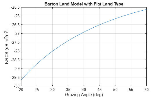
Plot the normalized radar cross-section for grazing angles from 20 to 60 degrees. Assume the default 'Barton' land Model and 'Flatland' LandType. Set the radar frequency to 1 GHz.
grazAng = 20:60; freq = 1e9; reflectivity = surfaceReflectivityLand; nrcs = reflectivity(grazAng,freq); plot(grazAng,pow2db(nrcs)) grid on xlabel('Grazing Angle (deg)') ylabel('NRCS (dB m^2/m^2)') title('Barton Land Model with Flat Land Type')

Configure a radarscenario to simulate a reflective land surface. Add a land surface object to define the physical properties of the scenario surface. The surface is a simple 200-by-200 meter rectangle. Use the surfaceReflectivityLand function to create a constant-gamma reflectivity model with a gamma value of -10 dB. Use the scenario landSurface method to add the rectangular land region and the radar reflectivity model to the scenario. Use a surface reference height of 16 meters.
scene = radarScenario(UpdateRate = 0, IsEarthCentered = false); refl = surfaceReflectivityLand(Model = "ConstantGamma", Gamma = -10); srf = landSurface(scene,RadarReflectivity = refl, ... Boundary=[-100 100; -100 100],ReferenceHeight = 16)
srf =
LandSurface with properties:
RadarReflectivity: [1×1 surfaceReflectivityLand]
ReflectionCoefficient: [1×1 radar.scenario.SurfaceReflectionCoefficient]
ReflectivityMap: 1
ReferenceHeight: 16
Boundary: [2×2 double]
Terrain: []
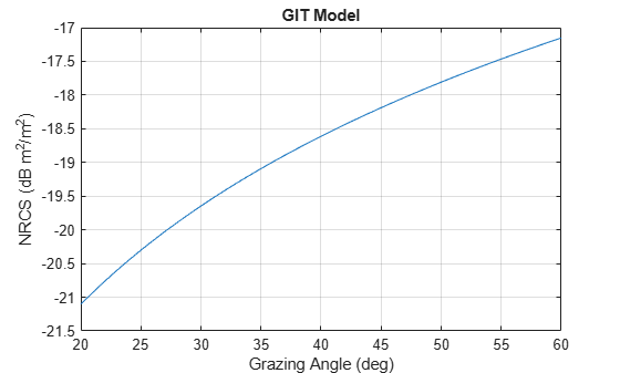
Create a normalized reflectivity object using the GIT 'Model' and a 'Soil' land type. Obtain the normalized radar cross-section at a frequency of 3 GHz over grazing angles from 20 to 60 degrees. Assume a surface height standard deviation of two meters. Plot the surface reflectivity.
grazAng = 20:60; freq = 10e9; reflectivity = surfaceReflectivityLand(Model="GIT", ... LandType="Soil",SurfaceHeightStandardDeviation=2); nrcs = reflectivity(grazAng,freq); plot(grazAng,pow2db(nrcs)) grid on xlabel('Grazing Angle (deg)') ylabel('NRCS (dB m^2/m^2)') title('GIT Model')

Create a normalized reflectivity object using the Billingsley 'Model' and a 'LowReliefRural' land type. Obtain the normalized radar cross-section at a frequency of 3 GHz over depression angles from 0.1 to 3 degrees. Plot the surface reflectivity.
depAng = 0.1:0.1:2;
freq = 3e9;
reflectivity = surfaceReflectivityLand(Model="Billingsley", ...
LandType="LowReliefRural");
nrcs = reflectivity(depAng,freq);
plot(depAng,pow2db(nrcs))
grid on
xlabel('Depression Angle (deg)')
ylabel('NRCS (dB m^2/m^2)')
title('Billingsley Model')
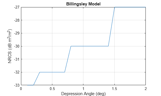
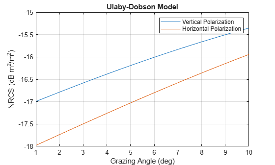
Create a normalized reflectivity object using the Ulaby-Dobson model for a grass land type. Obtain the normalized radar cross-section for both vertical and horizontal polarizations at a frequency of 10 GHz over grazing angles from 1 to 10 degrees. Plot the surface reflectivities.
grazAng = 1:0.1:10; freq = 10e9; reflectivity_v = surfaceReflectivityLand(Model="UlabyDobson", ... LandType="Grass",Polarization="V"); nrcs_v = reflectivity_v(grazAng,freq); reflectivity_h = surfaceReflectivityLand(Model="UlabyDobson", ... LandType="Grass",Polarization="H"); nrcs_h = reflectivity_h(grazAng,freq); plot(grazAng,pow2db(nrcs_v)) hold on plot(grazAng,pow2db(nrcs_h)) grid on legend('Vertical Polarization','Horizontal Polarization') xlabel('Grazing Angle (deg)') ylabel('NRCS (dB m^2/m^2)') title('Ulaby-Dobson Model')

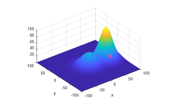
Create a surface with two hills. Plot the surface on a 200-by-200 meter grid with grid points one meter apart. Add the surface to a radar scenario. Assume the surface has a radar reflectivity defined by a constant gamma model.
[x,y] = meshgrid(linspace(-100,100,201)); ht1 = 40*exp(-(x.^2 + y.^2)/30^2); ht2 = 100*exp(-((x-60).^2 + y.^2)/25^2); ht = ht1 + ht2; p = surfc(x(1,:),y(:,1),ht); axis equal axis tight shading interp simTime = 3; scene = radarScenario(UpdateRate = 1, ... IsEarthCentered = false,StopTime = simTime); gammaDB = surfacegamma('Flatland'); refl = surfaceReflectivityLand(Model = 'ConstantGamma',Gamma = gammaDB); srf = landSurface(scene,RadarReflectivity = refl, ... Terrain = ht,Boundary = [-100,100;-100,100]);
Use surface manager to identify the surface.
scene.SurfaceManager
ans =
SurfaceManager with properties:
EnableMultipath: 0
UseOcclusion: 1
Surfaces: [1×1 radar.scenario.LandSurface]
scene.SurfaceManager.Surfaces
ans =
LandSurface with properties:
RadarReflectivity: [1×1 surfaceReflectivityLand]
ReflectionCoefficient: [1×1 radar.scenario.SurfaceReflectionCoefficient]
ReflectivityMap: 1
ReferenceHeight: 0
Boundary: [2×2 double]
Terrain: [201×201 double]
Obtain and plot the height of the surface at the point (50,-30).
xt = 50; yt = -30; htx = height(srf,[xt,yt])
htx = 21.1046
hold on plot3(xt,yt,htx+5,'ow','MarkerFaceColor','r') xlabel('x') ylabel('y') hold off

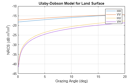
Create a land normalized reflectivity object using the Ulaby-Dobson model and a grass land type. Enable polarization and specify the cross-polarization reflectivity. Obtain the NRCS at a frequency of 10 GHz over grazing angles from 1 to 10 degrees. Plot the reflectivities.
grazAng = 0:0.1:20; freq = 10e9; surf = surfaceReflectivityLand(Model='UlabyDobson', ... LandType='Grass',EnablePolarization=true, ... GrazingAngle=0:.1:90,Frequency=[100,1e6,11e6], ... ReflectivityHV=0.05*sind(0:.1:90)'*[1 1 1], ... ReflectivityVH=0.04*sind(0:.1:90)'*[1 1 1])
surf =
surfaceReflectivityLand with properties:
EnablePolarization: 1
CrossPolarization: 'Full'
Model: 'UlabyDobson'
LandType: 'Grass'
ReflectivityHV: [901×3 double]
ReflectivityVH: [901×3 double]
Frequency: [100 1000000 11000000]
GrazingAngle: [0 0.1000 0.2000 0.3000 0.4000 0.5000 0.6000 0.7000 0.8000 0.9000 1 1.1000 1.2000 1.3000 1.4000 1.5000 1.6000 1.7000 1.8000 1.9000 2 2.1000 2.2000 2.3000 2.4000 2.5000 2.6000 2.7000 2.8000 2.9000 3 3.1000 3.2000 … ] (1×901 double)
Speckle: 'None'
nrcs = surf(grazAng,freq); plot(grazAng,pow2db(squeeze(nrcs(1,1,:))), ... grazAng,pow2db(squeeze(nrcs(2,2,:))), ... grazAng,pow2db(squeeze(nrcs(1,2,:))), ... grazAng,pow2db(squeeze(nrcs(2,1,:)))) legend('HH','VV','HV','VH'); grid on xlabel('Grazing Angle (deg)') ylabel('NRCS (dB m^2/m^2)') title('Ulaby-Dobson Model for Land Surface')

More About
| Model | Land Type | Range of Validity | Model-Specific Properties | ||||||||||||
|---|---|---|---|---|---|---|---|---|---|---|---|---|---|---|---|
|
|
|
| ||||||||||||
|
|
|
| ||||||||||||
|
|
|
| ||||||||||||
|
|
|
| ||||||||||||
|
|
|
| ||||||||||||
"Nathanson" – Applicable up to Ka band for low grazing
angle surface radars and medium grazing angle airborne radars for low mountains,
farmland, and wooded areas. See [3]. |
|
|
| ||||||||||||
|
|
|
| ||||||||||||
| See Constant Gamma Model. |
|
The constant-gamma model expresses a simple analytic relationship between the normalized radar cross-section and grazing angle.
σ = 10(γ/10)sin(θ)
γ is defined by the Gamma property and
θ is the grazing angle input argument graz given
in degrees.
Speckle is modeled as an uncorrelated, multiplicative factor I = σ*n, where σ is the clutter RCS and n represents random numbers drawn from an independent identically-distributed unity mean noise statistical distribution. Because speckle is correlated with underlying terrain RCS, it is usually applied to radar intensity. Speckle noise model distributions include lognormal, Rayleigh, and Weibull.
References
[1] Barton, David Knox. Radar Equations for Modern Radar. Artech House, 2013.
[2] Long, Maurice W. Radar Reflectivity of Land and Sea. 3rd ed, Artech House, 2001.
[3] Nathanson, Fred E., et al. Radar Design Principles: Signal Processing and the Environment. 2. ed., Repr, Scitech Publ, 2004.
[4] Reilly, J. P., R. L. McDonald, and G. D. Dockery. "RF-Environment Models for the ADSAM Program." Report No. A1A97U-070, Laurel, MD: Johns Hopkins University Applied Physics Laboratory, August 22, 1997.
[5] Billingsley, J. Barrie. Low-Angle Radar Land Clutter: Measurements and Empirical Models. William Andrew Pub. : SciTech Pub. ; Institution of Electrical Engineers, 2002.
[6] Richards, M. A., et al., editors. Principles of Modern Radar. SciTech Pub, 2010.
[7] Morchin, Fred E., J. Patrick Reilly, and Marvin Cohen. Radar Design Principles: Signal Processing and the Environment. 2nd ed. New York: McGraw-Hill, 1991.
[8] Ulaby, Fawwaz T., and M. Craig Dobson. Handbook of Radar Scattering Statistics for Terrain. Artech House, 1989.
Extended Capabilities
C/C++ Code Generation
Generate C and C++ code using MATLAB® Coder™.
Version History
Introduced in R2022a
MATLAB Command
You clicked a link that corresponds to this MATLAB command:
Run the command by entering it in the MATLAB Command Window. Web browsers do not support MATLAB commands.
Web サイトの選択
Web サイトを選択すると、翻訳されたコンテンツにアクセスし、地域のイベントやサービスを確認できます。現在の位置情報に基づき、次のサイトの選択を推奨します:
また、以下のリストから Web サイトを選択することもできます。
最適なサイトパフォーマンスの取得方法
中国のサイト (中国語または英語) を選択することで、最適なサイトパフォーマンスが得られます。その他の国の MathWorks のサイトは、お客様の地域からのアクセスが最適化されていません。
南北アメリカ
- América Latina (Español)
- Canada (English)
- United States (English)
ヨーロッパ
- Belgium (English)
- Denmark (English)
- Deutschland (Deutsch)
- España (Español)
- Finland (English)
- France (Français)
- Ireland (English)
- Italia (Italiano)
- Luxembourg (English)
- Netherlands (English)
- Norway (English)
- Österreich (Deutsch)
- Portugal (English)
- Sweden (English)
- Switzerland
- United Kingdom (English)