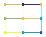
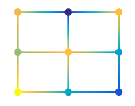
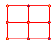
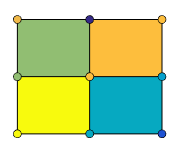
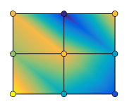
surface
基本的な表面プロット
構文
説明
surface( は、現在の座標軸ではなく、ax,___)ax で指定される座標軸にプロットします。座標軸を最初の入力引数として指定します。
surface(___, は、1 つ以上の名前と値のペアの引数を使用して、表面のプロパティを指定します。たとえば、Name,Value)'FaceAlpha',0.5 は半透明な表面を作成します。
s = surface(___) はチャートの primitive surface オブジェクトを返します。表面を作成した後で変更を加えるには、s を使用します。プロパティの一覧については、Surface のプロパティ を参照してください。
例
同じサイズの 3 つの行列を作成します。次に、それらを表面としてプロットします。表面では、高さと色の両方に Z が使用されます。
[X,Y] = meshgrid(1:0.5:10,1:20);
Z = sin(X) + cos(Y);
surface(X,Y,Z)
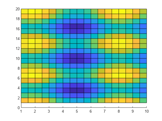
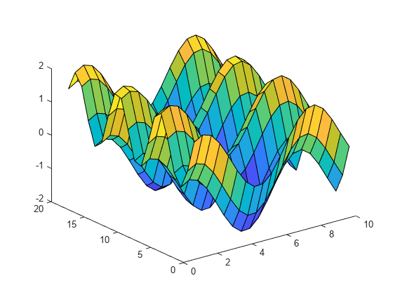
既定では、表面は 2 次元表示を使用した座標軸に表示されます。座標軸を 3 次元表示に変更します。
view(3)
4 番目の行列入力 C を使用して、表面プロットの色を指定します。このメッシュ プロットでは、Z を高さに、C を色に使用します。"カラーマップ" を使用して色を指定します。カラーマップは、単一の数値を使用してスペクトル上の色を表します。カラーマップを使用する場合、C は Z と同じサイズです。カラー バーをグラフに追加して、C のデータ値がカラーマップの色にどのように対応するかを示し、プロットの表示を既定の 3 次元表示に設定します。
[X,Y] = meshgrid(1:0.5:10,1:20);
Z = sin(X) + cos(Y);
C = X.*Y;
surface(X,Y,Z,C)
colorbar
view(3)

名前 FaceAlpha と値 0.5 のペアを指定して、半透明の表面を作成します。その後の変更を可能にするには、surface オブジェクトを変数 s に代入します。
[X,Y] = meshgrid(-5:.5:5);
Z = Y.*sin(X) - X.*cos(Y);
s = surface(X,Y,Z,'FaceAlpha',0.5);
view(3)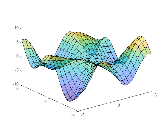
surface オブジェクトの作成後にそのプロパティにアクセスし、変更を加えるには、s を使用します。たとえば、EdgeColor プロパティを設定することでエッジを非表示にします。
s.EdgeColor = 'none';
表面を作成し、それに沿ってイメージを表示します。
同じサイズの 3 つの行列を作成します。
[pX,pY,pZ] = peaks(25);
地球のイメージを含むデータセットを読み込みます。イメージ データがワークスペース変数 X に現れ、関連付けられたカラーマップが map に現れます。
load earth
who
Your variables are: X map pX pY pZ
表面プロットを作成して、表面に沿ってイメージを表示します。表面データ pZ とカラー データ X のサイズが異なるため、表面の FaceColor を 'texturemap' に設定します。プロットの表示を既定の 3 次元表示に設定します。
surface(pX,pY,pZ,X,'FaceColor','texturemap', ...
    'EdgeColor','none','CDataMapping','direct')
colormap(map)
view(3)

入力引数
x 座標。Z と同じサイズの行列、または長さが n のベクトル ([m,n] = size(Z)) として指定します。X と Y の値を指定しない場合、surface はベクトル (1:n) とベクトル (1:m) を使用します。
行列 X と行列 Y を作成するには、関数 meshgrid を使用できます。
Surface オブジェクトの XData プロパティに x 座標が格納されます。
例: X = 1:10
例: X = [1 2 3; 1 2 3; 1 2 3]
例: [X,Y] = meshgrid(-5:0.5:5)
データ型: single | double | int8 | int16 | int32 | int64 | uint8 | uint16 | uint32 | uint64 | categorical | datetime | duration
y 座標。Z と同じサイズの行列、または長さ m のベクトルとして指定します。ここで、[m,n] = size(Z) です。X と Y の値を指定しない場合、surface はベクトル (1:n) とベクトル (1:m) を使用します。
行列 X と行列 Y を作成するには、関数 meshgrid を使用できます。
surface オブジェクトの YData プロパティには y 座標が保存されます。
例: Y = 1:10
例: Y = [1 1 1; 2 2 2; 3 3 3]
例: [X,Y] = meshgrid(-5:0.5:5)
データ型: single | double | int8 | int16 | int32 | int64 | uint8 | uint16 | uint32 | uint64 | categorical | datetime | duration
z 座標。行列として指定します。Z は少なくとも 2 行 2 列でなければなりません。
Z は、各 x-y 座標での表面プロットの高さを指定します。色を指定しない場合、Z は表面の色も指定します。
surface オブジェクトの ZData プロパティには z 座標が保存されます。
例: Z = [1 2 3; 4 5 6]
例: Z = sin(x) + cos(y)
データ型: single | double | int8 | int16 | int32 | int64 | uint8 | uint16 | uint32 | uint64 | categorical | datetime | duration
色配列。m 行 n 列のカラーマップ インデックスの行列、または m×n×3 の RGB 3 成分の配列として指定します。ここで、Z は m 行 n 列です。
カラーマップの色を使用するには、
Cを行列として指定します。表面の各グリッド点について、Cはカラーマップ内の色を示します。surface オブジェクトのCDataMappingプロパティは、Cの値がカラーマップの色にどのように対応するかを制御します。トゥルーカラーの色を使用するには、
Cを RGB 3 成分の配列として指定します。
詳細については、カラーマップとトゥルーカラーの違いを参照してください。
surface オブジェクトの CData プロパティには色配列が保存されます。表面のカラーリングをさらに制御するには、FaceColor プロパティと EdgeColor プロパティを使用します。
プロットする座標軸。Axes オブジェクトまたは PolarAxes オブジェクトとして指定します。座標軸を指定しない場合、surface は現在の座標軸にプロットするか Axes オブジェクト (直交座標軸) を作成します。
名前と値の引数
オプションの引数のペアを Name1=Value1,...,NameN=ValueN として指定します。ここで、Name は引数名で、Value は対応する値です。名前と値の引数は他の引数の後に指定しなければなりませんが、ペアの順序は重要ではありません。
R2021a より前では、コンマを使用して名前と値をそれぞれ区切り、Name を引用符で囲みます。
例: surface(X,Y,Z,'FaceAlpha',0.5,'EdgeColor','none') は、エッジが描画されない半透明の表面を作成します。
メモ
ここには一部のプロパティのみを示します。完全な一覧については、Surface のプロパティ を参照してください。
エッジのラインの色。次のいずれかの値として指定します。既定の色は [0 0 0] で、これは黒色のエッジに対応します。
| 値 | 説明 |
|---|---|
'none' | エッジを描画しません。 |
'flat' |
|
'interp' |
|
| RGB 3 成分、16 進数カラー コード、色名 | 指定した色をすべてのエッジに使用します。このオプションは
|
RGB 3 成分および 16 進数カラー コードは、カスタム色を指定するのに役立ちます。
RGB 3 成分は、色の赤、緑、青成分の強度を指定する 3 成分の行ベクトルです。強度値は
[0,1]の範囲でなければなりません。たとえば[0.4 0.6 0.7]のようになります。16 進数カラー コードは、ハッシュ記号 (
#) で始まり、3 桁または 6 桁の0からFまでの範囲の 16 進数が続く文字ベクトルまたは string スカラーです。この値は大文字と小文字を区別しません。したがって、カラー コード"#FF8800"、"#ff8800"、"#F80"、および"#f80"は等価です。
あるいは、名前を使用して一部の一般的な色を指定できます。次の表に、名前の付いた色オプション、等価の RGB 3 成分、および 16 進数カラー コードを示します。
| 色名 | 省略名 | RGB 3 成分 | 16 進数カラー コード | 外観 |
|---|---|---|---|---|
"red" | "r" | [1 0 0] | "#FF0000" |
|
"green" | "g" | [0 1 0] | "#00FF00" |
|
"blue" | "b" | [0 0 1] | "#0000FF" |
|
"cyan" | "c" | [0 1 1] | "#00FFFF" |
|
"magenta" | "m" | [1 0 1] | "#FF00FF" |
|
"yellow" | "y" | [1 1 0] | "#FFFF00" |
|
"black" | "k" | [0 0 0] | "#000000" |
|
"white" | "w" | [1 1 1] | "#FFFFFF" |
|
次の表に、ライト テーマとダーク テーマでのプロットの既定のカラー パレットを示します。
| パレット | パレットの色 |
|---|---|
R2025a より前: ほとんどのプロットで、これらの色が既定で使用されます。 |
|
|
|
orderedcolors 関数と rgb2hex 関数を使用すると、これらのパレットの RGB 3 成分および 16 進数カラー コードを取得できます。たとえば、"gem" パレットの RGB 3 成分を取得し、16 進数カラー コードに変換します。
RGB = orderedcolors("gem");
H = rgb2hex(RGB);
R2023b より前: RGB = get(groot,"FactoryAxesColorOrder") を使用して、RGB 3 成分を取得します。
R2024a より前: H = compose("#%02X%02X%02X",round(RGB*255)) を使用して、16 進数カラー コードを取得します。
ライン スタイル。次の表にリストされたオプションのいずれかとして指定します。
| ライン スタイル | 説明 | 結果として得られる線 |
|---|---|---|
"-" | 実線 |
|
"--" | 破線 |
|
":" | 点線 |
|
"-." | 一点鎖線 |
|
"none" | ラインなし | ラインなし |
面の色。次の表のいずれかの値として指定します。
| 値 | 説明 |
|---|---|
'flat' |
|
'interp' |
|
| RGB 3 成分、16 進数カラー コード、色名 | 指定した色をすべての面で使用します。このオプションは
|
'texturemap' | CData のカラー データを表面に適合するように変換します。 |
'none' | 面を描画しません。 |
RGB 3 成分および 16 進数カラー コードは、カスタム色を指定するのに役立ちます。
RGB 3 成分は、色の赤、緑、青成分の強度を指定する 3 成分の行ベクトルです。強度値は
[0,1]の範囲でなければなりません。たとえば[0.4 0.6 0.7]のようになります。16 進数カラー コードは、ハッシュ記号 (
#) で始まり、3 桁または 6 桁の0からFまでの範囲の 16 進数が続く文字ベクトルまたは string スカラーです。この値は大文字と小文字を区別しません。したがって、カラー コード"#FF8800"、"#ff8800"、"#F80"、および"#f80"は等価です。
あるいは、名前を使用して一部の一般的な色を指定できます。次の表に、名前の付いた色オプション、等価の RGB 3 成分、および 16 進数カラー コードを示します。
| 色名 | 省略名 | RGB 3 成分 | 16 進数カラー コード | 外観 |
|---|---|---|---|---|
"red" | "r" | [1 0 0] | "#FF0000" |
|
"green" | "g" | [0 1 0] | "#00FF00" |
|
"blue" | "b" | [0 0 1] | "#0000FF" |
|
"cyan" | "c" | [0 1 1] | "#00FFFF" |
|
"magenta" | "m" | [1 0 1] | "#FF00FF" |
|
"yellow" | "y" | [1 1 0] | "#FFFF00" |
|
"black" | "k" | [0 0 0] | "#000000" |
|
"white" | "w" | [1 1 1] | "#FFFFFF" |
|
次の表に、ライト テーマとダーク テーマでのプロットの既定のカラー パレットを示します。
| パレット | パレットの色 |
|---|---|
R2025a より前: ほとんどのプロットで、これらの色が既定で使用されます。 |
|
|
|
orderedcolors 関数と rgb2hex 関数を使用すると、これらのパレットの RGB 3 成分および 16 進数カラー コードを取得できます。たとえば、"gem" パレットの RGB 3 成分を取得し、16 進数カラー コードに変換します。
RGB = orderedcolors("gem");
H = rgb2hex(RGB);
R2023b より前: RGB = get(groot,"FactoryAxesColorOrder") を使用して、RGB 3 成分を取得します。
R2024a より前: H = compose("#%02X%02X%02X",round(RGB*255)) を使用して、16 進数カラー コードを取得します。
面の透明度。次の値のいずれかとして指定します。
範囲
[0,1]のスカラー — すべての面に一様な透明度を使用します。値1は完全に不透明で、値0は完全に透明です。0と1の間の値は半透明です。このオプションはAlphaDataプロパティの透明度値を使用しません。'flat'—AlphaDataプロパティの値に基づいて面ごとに異なる透明度を使用します。面全体の透明度は、最初の頂点の透明度値によって決まります。まずAlphaDataプロパティをZDataプロパティと同じサイズの行列として指定しなければなりません。FaceColorプロパティも、'flat'に設定しなければなりません。'interp'—AlphaDataプロパティの値に基づいて面ごとに内挿された透明度を使用します。頂点の値を内挿することにより、各面に異なる透明度が使用されます。まずAlphaDataプロパティをZDataプロパティと同じサイズの行列として指定しなければなりません。FaceColorプロパティも、'interp'に設定しなければなりません。'texturemap'—AlphaDataのデータを表面に適合するように変換します。
面に対する light オブジェクトの効果。次の値のいずれかとして指定します。
'flat'— 各面にライトを一様に適用します。この値は小平面で構成されたオブジェクトを表示する場合に使用します。'gouraud'— 面のライトを変化させます。各頂点のライトを計算し、面上でライトを線形内挿します。この値は曲面を表示する場合に使用します。'none'— light オブジェクトのライトを面に適用しません。
light オブジェクトを座標軸に追加するには、関数 light を使用します。
メモ
値 'phong' は削除されました。代わりに 'gouraud' を使用してください。
バージョン履歴
R2006a より前に導入極座標で表面プロットを作成するには、最初の引数として PolarAxes オブジェクトを指定します。
参考
関数
プロパティ
MATLAB Command
You clicked a link that corresponds to this MATLAB command:
Run the command by entering it in the MATLAB Command Window. Web browsers do not support MATLAB commands.
Web サイトの選択
Web サイトを選択すると、翻訳されたコンテンツにアクセスし、地域のイベントやサービスを確認できます。現在の位置情報に基づき、次のサイトの選択を推奨します:
また、以下のリストから Web サイトを選択することもできます。
最適なサイトパフォーマンスの取得方法
中国のサイト (中国語または英語) を選択することで、最適なサイトパフォーマンスが得られます。その他の国の MathWorks のサイトは、お客様の地域からのアクセスが最適化されていません。
南北アメリカ
- América Latina (Español)
- Canada (English)
- United States (English)
ヨーロッパ
- Belgium (English)
- Denmark (English)
- Deutschland (Deutsch)
- España (Español)
- Finland (English)
- France (Français)
- Ireland (English)
- Italia (Italiano)
- Luxembourg (English)
- Netherlands (English)
- Norway (English)
- Österreich (Deutsch)
- Portugal (English)
- Sweden (English)
- Switzerland
- United Kingdom (English)
