このページは機械翻訳を使用して翻訳されました。最新版の英語を参照するには、ここをクリックします。
HDL コシミュレーション ブロックの HDL コードをインポートする
コシミュレーションタイプ—Simulinkブロック
モデルを開き、アプリ タブで HDL Verifier をクリックします。次に、Mode セクションで HDL Cosimulation を選択し、Import HDL Files をクリックして Cosimulation Wizard を開きます。

HDL Simulator には
ModelSim、Xcelium、またはVivado Simulatorを選択します。ファイルがUse HDL simulator executables on the system pathにある場合は、それを選択します。コシミュレーション ウィザードは、デフォルトでそれらがシステム パス上にあると想定します。
HDL シミュレータ実行ファイルがシステム パス上に 存在しない 場合は、Use the following HDL simulator executables at the following location を選択し、下のテキスト ボックスでフォルダーの場所を指定します。
Next をクリックしても Cosimulation Wizard が実行可能ファイルを見つけられない場合は、次のようになります。
このダイアログに戻り、コシミュレーション ウィザードのステータス ペインにエラーが表示されます。
コシミュレーション ウィザードはオプションを Use the following HDL simulator executables at the following location に切り替えます。
コシミュレーション ウィザードにより、HDL シミュレーション パス フィールドを編集できるようになります。
続行する前に、HDL シミュレータ実行可能ファイルへの有効なパスを入力する必要があります。
[Next] をクリックします。
HDL ファイル - Simulink ブロック

HDL Files ペインで、関数またはブロックの作成に使用するファイルを指定します。
コシミュレーション ウィザードは、各ファイルのファイル タイプを判別し、ファイル名の横の File List にそのタイプを表示しようとします。コシミュレーション ウィザードがタイプを判別できない場合、または間違ったタイプが表示される場合は、File Type 列でタイプを直接変更できます。
可能であれば、コシミュレーション ウィザードは HDL シミュレータが提供する機能を使用してコンパイル順序を自動的に決定します。つまり、ファイルを任意の順序で追加できます。
ModelSim® を使用している場合は、コンパイル スクリプトが .do ファイル (ModelSim マクロ ファイル) としてリストされます。Xcelium™ を使用している場合は、コンパイル スクリプトがシステム スクリプトとしてリストされます。
Add をクリックして、1 つ以上のファイル名を選択します。
ファイルを削除するには、まず File List でファイル名を強調表示し、次に Remove Selected File をクリックします。
[Next] をクリックします。
HDL コンパイル - Simulink ブロック

HDL Compilation ペインでは、生成された HDL コンパイル コマンドを確認できます。必要に応じて、これらのコマンドを上書きしたりカスタマイズしたりすることができます。HDL ファイルの代わりにコンパイル スクリプトを含めた場合、このペインにはそれらのスクリプトを実行するコマンドが表示されます。
コマンドの変更を Compilation Commands ボックスに入力します。
メモ
システム シェル コマンドを含めないでください。例:
set file = a.vhd vcom $file
コマンドの実行から制御が Cosimulation Wizard に戻ると、変数には設定された値が保持されなくなります。このタイプのコマンドを含めようとすると、Status パネルにエラーが表示されます。
生成された HDL コンパイル コマンドに戻るには、Restore default commands をクリックします。変更を破棄するかどうかを確認するメッセージが表示されます。
続行するにはNextをクリックしてください。
シミュレーション オプション - Simulink ブロック
Modelsim または Xcelium ユーザー:

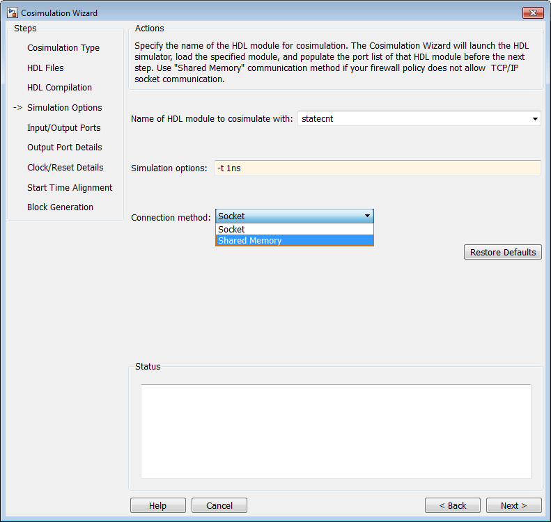
Simulation Options ペインで、コシミュレーションで使用する HDL モジュールの名前を指定します。
Name of HDL module to cosimulate with にモジュールの名前を入力します。
Simulation options で追加のシミュレーション オプションを指定します。たとえば、前の画像では、次のオプションが表示されています。
HDLシミュレータの解像度
シミュレーションビューから信号を削除する最適化をオフにする
オプションをデフォルトに戻すには、Restore Defaults をクリックします。
Connection method の場合、ファイアウォール ポリシーで TCP/IP ソケット通信が許可されていない場合は、
Shared Memoryを選択します。次のステップに進むには、Next をクリックしてください。プロセスのこの時点で、アプリケーションはコマンド ウィンドウで次のアクションを実行します。
HDL シミュレータを起動します。
HDL シミュレータに HDL モジュールをロードします。
HDL サーバーを起動し、サーバーが起動したという通知を受信するまで待機します。
HDL サーバーに接続してポート情報を取得します。
HDL サーバーを切断してシャットダウンします。
Next をクリックすると、パラメータ設定ファイルも生成されます。詳細については、コシミュレーションで HDL パラメータを使用するを参照してください。
Vivado シミュレータ ユーザー:

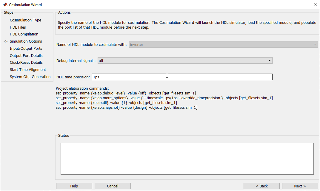
Vivado® コシミュレーション用のシステム オブジェクトを作成するときに、ウィザードに HDL トップ モジュールの名前が表示されます。
波形ファイルを生成するには、Debug internal signals を
waveに設定します。HDL time precision パラメータでは、シミュレーション時間の精度を変更することもできます。
Next をクリックして共有ライブラリ (dll ファイル) を作成します。
Vivado コシミュレーションの場合、このステップでは共有ライブラリが作成されます。
入力/出力ポート—Simulink ブロック

Simulink Ports ペインで、各入力ポートと出力ポートのタイプを指定します。
コシミュレーション ウィザードはポート タイプを決定しようとしますが、設定を上書きすることもできます。サポートされているデータ型については、サポートされているデータ型 を参照してください。
入力ポートには、
Input、Clock、Reset、またはUnusedを選択します。出力ポートには、
OutputまたはUnusedを選択します。Simulink® は、Tcl コマンドを通じて HDL シミュレーターにクロック信号とリセット信号を強制します。クロックとリセット信号のタイミングは後のステップで指定できます (クロック/リセットの詳細—Simulink ブロック を参照)。
HDL クロックおよびリセット信号を Simulink 信号で駆動するには、それらを
Inputとしてマークします。
Next をクリックして 出力ポートの詳細 - Simulink ブロック に進みます。
出力ポートの詳細 - Simulink ブロック

Output Port Details ペインで、すべての出力ポートのサンプル時間とデータ型を設定します。
サンプル時間のデフォルトは
1、データ タイプのデフォルトはInheritとSignedです。これらのデフォルトは、HDL Cosimulation ブロック マスク (Ports タブ) が出力ポートのデフォルト設定を設定する方法と一致しています。Set all sample times and data types to 'Inherit' を選択した場合、ポートはバックプロパゲーションによって時間を継承します (サンプル時間は -1 に設定されます)。ただし、状況によってはバックプロパゲーションが失敗する場合があります。サンプル時間の逆伝播 (Simulink) を参照してください。
[Next] をクリックします。
クロック/リセットの詳細—Simulink ブロック

Clock/Reset Details ペインで、クロックを設定し、パラメータをリセットします。
ここで指定する期間は、HDL シミュレータ内の時間を指します。
クロックのデフォルト設定は、立ち上がりアクティブ エッジと 10 ns の周期です。
リセットのデフォルト設定は、初期値が 1、期間が 8 ns です。
次の画面にはシミュレーションの開始時刻が視覚的に表示され、クロックとリセットがどのように並んでいるかを確認できます。
[Next] をクリックします。
開始時刻の調整 - Simulink ブロック

Start Time Alignment ペインで、クロックとリセットの現在の設定を確認します。このダイアログの目的は 2 つあります。
立ち上がりエッジまたは立ち下がりエッジが期待通りに設定されていることを確認する(前の手順から)
開始時間を調べます。クロックのアクティブ エッジと一致する場合は、HDL シミュレータの開始時間を調整する必要があります。
リセット信号を調べます。クロックのアクティブ エッジと同期している場合は、競合状態が発生する可能性があります。
競合状態を回避するには、開始時間がクロックのアクティブ エッジと一致しないようにしてください。これは、開始時間を移動するか、前の手順でクロックのアクティブ エッジを変更することで実行できます。
開始時間が希望どおりであることを確認します。
HDL シミュレータの開始時間は、前のペインのクロックとリセット値から計算されます。必要に応じて、HDL time to start cosimulation (ns) の部分に新しい値を入力して、HDL シミュレータの開始時間を変更できます。変更が適用されたことを確認するには、「Update plot」をクリックします。
[Next] をクリックします。
ブロックを生成

Automatically determine timescale at start of simulation を選択して、シミュレーションを開始するときに HDL Verifier™ でタイムスケールを決定するかどうかを指定します。タイムスケールを自分で決定する場合は、このボックスのチェックを外して、下のテキスト ボックスにタイムスケールの値を入力します。デフォルトでは、タイムスケールが自動的に決定されます。
タイムスケールの詳細については、シミュレーションのタイムスケール を参照してください。
設定を確認または変更するには、Back をクリックします。
Finish をクリックして HDL コシミュレーション ブロックを生成します。
完全なSimulinkモデル
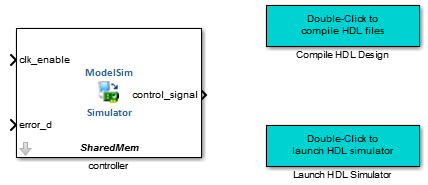
Cosimulation Wizard ツールは、モデルに次の項目を挿入します。
ModelSim または Xcelium ユーザー:
HDL Cosimulation ブロック
HDL設計をコンパイルするためのユーティリティ関数
HDLシミュレータを起動するためのユーティリティ関数

Vivado ユーザー:
HDL Cosimulation ブロック
DLLファイルを生成するユーティリティブロック

HDL Cosimulation ブロックへの入力と出力が一直線になるようにブロックを配置します。
宛先モデル内のブロックを HDL Cosimulation ブロックに接続します。
メモ
Cosimulation Wizard を Simulink ツールストリップからではなくコマンド ラインから開いた場合、HDL Cosimulation とユーティリティ関数は新しいモデルで開きます。まずそれらをモデルにコピーする必要があります。
モデルが完成したら、HDL コシミュレーションの次の手順については コシミュレーションの実行 を参照してください。