片持ちビームの線形解析
この例では、ビームの構造モデルを取得して、インパルス力の影響を受けるときの時間と周波数応答を計算する方法を説明します。この例の場合、先端で点荷重を受ける鉄の片持ちビームについて考えます。構造モデルの作成には、Partial Differential Equation Toolbox™ のライセンスが必要です。
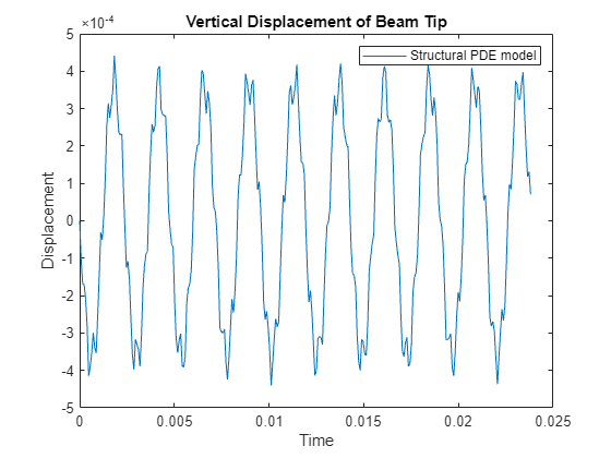
鉄のビームは、ビームの先端で 100 N の外部負荷を加えてから放すと変形します。この例では追加の負荷を使用しないため、先端の変位は加えられた力からの初期変位と同等の振幅で振動します。この例は 3 ステップのワークフローを使用します。
ビームの構造モデルを作成します。
構造モデルを線形化して、ビームのスパース線形モデルを取得します。
線形化したモデルの時間応答と周波数応答を解析します。

ビームの構造モデル
Partial Differential Equation Toolbox を使用して、構造モデルを作成し、インパルス応答を計算します。片持ちビームのモデル化の例については、Dynamics of Damped Cantilever Beam (Partial Differential Equation Toolbox)を参照してください。
最初にビームを作成し、鉄のヤング率、ポアソン比、質量密度を指定します。関数 addVertex を使用してビームの先端を指定します。
gm = multicuboid(0.1,0.005,0.005);
E = 210E9;
nu = 0.3;
rho = 7800;
TipVertex = addVertex(gm,Coordinates=[0.05,0,0.005]);
createpde (Partial Differential Equation Toolbox)を使用して構造モデルを作成し、generateMesh (Partial Differential Equation Toolbox)コマンドを使用してメッシュを生成します。
sModel = createpde(structural="transient-solid");
sModel.Geometry = gm;
msh = generateMesh(sModel);
pdegplot (Partial Differential Equation Toolbox)を使用してビームのジオメトリを可視化します。
figure
pdegplot(sModel,FaceLabels="on");
title("Beam model")
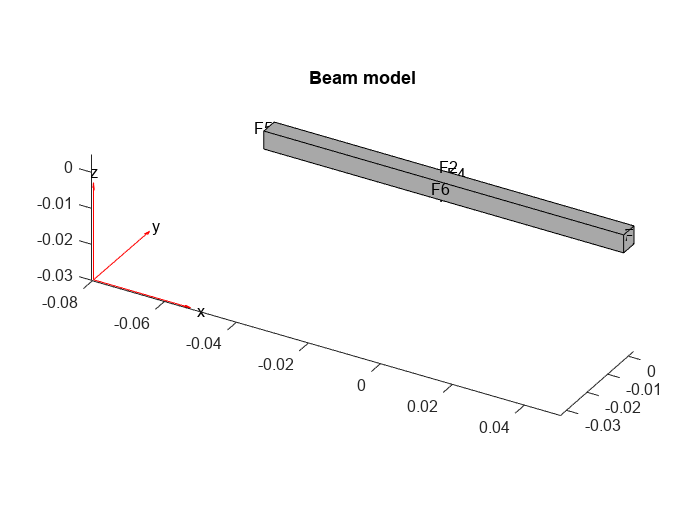
structuralProperties (Partial Differential Equation Toolbox)コマンドで鉄のビームに構造特性を割り当て、structuralBC (Partial Differential Equation Toolbox)を使用して一方の端を固定します。
structuralProperties(sModel,YoungsModulus=E,PoissonsRatio=nu,MassDensity=rho);
structuralBC(sModel,Face=5,Constraint="fixed");
solve (Partial Differential Equation Toolbox)を使用して指定した周波数範囲でモード解析モデルを解いて、ビームの振動モードを計算できます。このビームの最初の振動モードは、この例の線形解析の節でボード線図により確認できるように、2639 rad/s です。
firstNF = 2639;
Tfundamental = 2*pi/firstNF;
ビームの先端に対するインパルス (ノック) をモデル化するには、structuralBoundaryLoad (Partial Differential Equation Toolbox)を使用して、発振 (インパルス) の基本周期 2% の間に力を加えます。この力を線形化の入力として使用するラベル force を指定します。
Te = 0.02*Tfundamental;
structuralBoundaryLoad(sModel,Vertex=TipVertex,Force=[0;0;-100], ...
                              EndTime=Te,Label="force");
structuralIC (Partial Differential Equation Toolbox)を使用してビーム モデルの初期条件を設定します。
structuralIC(sModel,Velocity=[0;0;0]);
構造ビーム モデルを解くことにより、インパルス応答を計算します。
ncycles = 10;
tsim = linspace(0,ncycles*Tfundamental,30*ncycles);
R1 = solve(sModel,tsim);
ビームの先端で発振を可視化します。
figure
plot(tsim,R1.Displacement.uz(TipVertex,:))
title('Vertical Displacement of Beam Tip')
legend('Structural PDE model')
xlabel('Time')
ylabel('Displacement')
構造モデルの線形化
このビーム モデルで、先端に加えられた力から先端の z 変位への線形モデル (伝達関数) を取得します。
そのためには、最初に構造モデルについて線形化されるモデルの入出力を指定します。ここでは、入力はstructuralBoundaryLoad (Partial Differential Equation Toolbox)で指定された力であり、出力は先端の頂点の z 自由度です。
linearizeInput(sModel,"force");
linearizeOutput(sModel,Vertex=TipVertex,Component="z");
次に、linearize (Partial Differential Equation Toolbox) コマンドを使用して mechss モデルを抽出します。
sys = linearize(sModel)
Sparse continuous-time second-order model with 1 outputs, 3 inputs, and 3303 degrees of freedom.
Model Properties

Use "spy" and "showStateInfo" to inspect model structure.
Type "help mechssOptions" for available solver options for this model.
線形化されたモデルには、先端の頂点に加えられた力の x、y、z コンポーネントに対応する 3 つの入力があります。
sys.InputName
ans = 3×1 cell
    {'force_x'}
    {'force_y'}
    {'force_z'}
線形化されたモデルで、力の z コンポーネントを選択します。
sys = sys(:,3)
Sparse continuous-time second-order model with 1 outputs, 1 inputs, and 3303 degrees of freedom.
Model Properties

Use "spy" and "showStateInfo" to inspect model structure.
Type "help mechssOptions" for available solver options for this model.
結果のモデルは次の方程式のセットで定義されます。
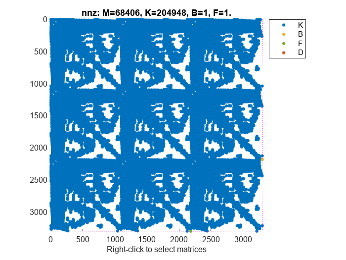
spyを使用して mechss モデル sys のスパース性を可視化します。
figure
spy(sys)
線形解析
'tfbdf3' を微分代数方程式 (DAE) ソルバーとして選択します。
sys.SolverOptions.DAESolver = "trbdf3";bodeを使用して、線形化されたモデル sys の周波数応答を計算します。
w = logspace(2,6,1000);
figure
bode(sys,w)
grid
title("Frequency Response from Force to Tip Vertical Displacement")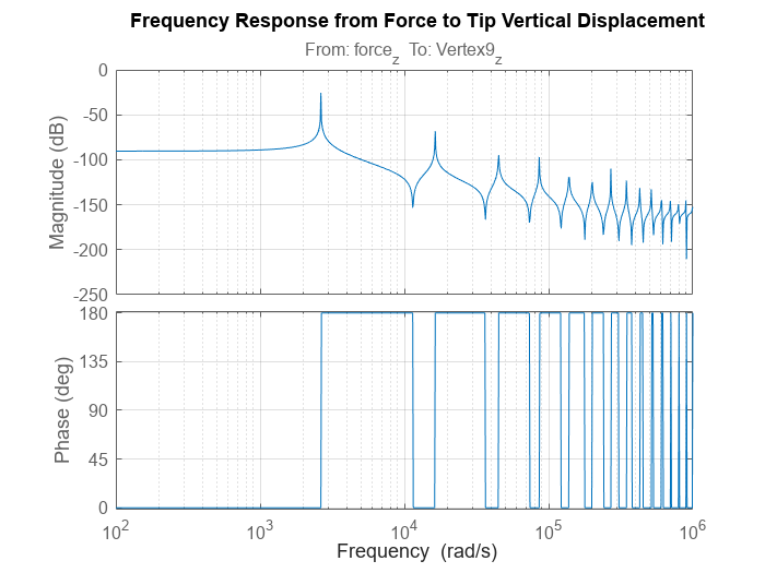
ボード線図には、最初の振動モードがおよそ firstNF = 2639 rad/s であることが示されます。
次に、lsimを使用してインパルス応答をシミュレートし、PDE モデルの結果と比較します。サンプル間の力の線形内挿による誤差を制限するには、Te/5 のステップ サイズを使用します。力は短い時間間隔 [0 Te] でビームの先端に加えられることに注意してください。
h = Te/5;
t = 0:h:ncycles*Tfundamental;
u = zeros(size(t));
u(t<=Te) = -100;

y = lsim(sys,u,t);
figure
plot(t,y,tsim,R1.Displacement.uz(TipVertex,:))
title({'Comparison of Sparse LSIM Response';...
        'with PDE Model Simulation'})
legend("Linearized model','Structural PDE model")
xlabel("Time")
ylabel("Displacement")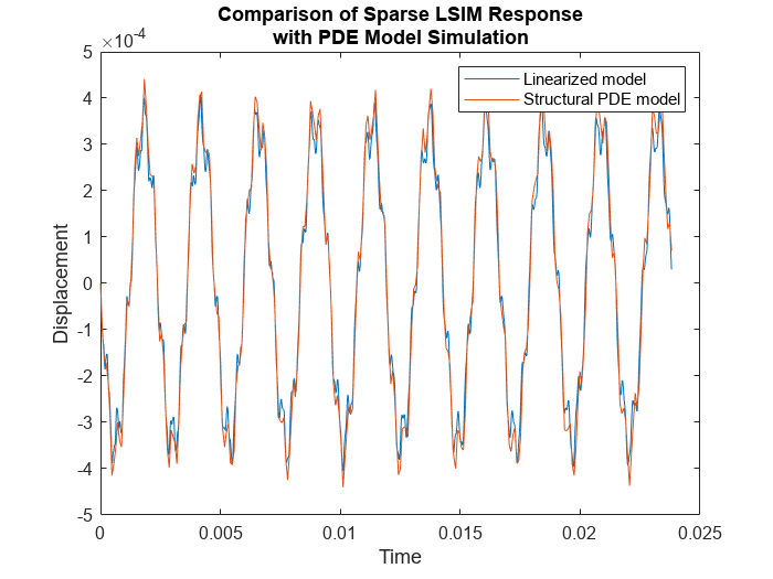
lsim からの線形応答は、最初のステップで取得した構造モデルの過渡シミュレーションにほぼ一致しています。
参考
showStateInfo | spy | mechss | solve (Partial Differential Equation Toolbox) | structuralBC (Partial Differential Equation Toolbox) | structuralIC (Partial Differential Equation Toolbox) | createpde (Partial Differential Equation Toolbox) | linearize (Partial Differential Equation Toolbox) | linearizeInput (Partial Differential Equation Toolbox) | linearizeOutput (Partial Differential Equation Toolbox)