Modeling and Simulating an All-Digital Phase Locked Loop
By Russell Mohn, Epoch Microelectronics Inc.
Implementing a PLL design on silicon can consume months of development time and hundreds of thousands of dollars in fabrication costs. To minimize these costs, engineers need a way to predict whether the design will meet specifications before implementing the design on silicon.
Simulation is an obvious solution, but it, too, can be difficult because of the vastly different time scales involved in PLL design. Phase lock time is usually measured in hundreds of microseconds, while femtosecond resolution is required to evaluate phase noise. It can take days to weeks of computing time to run a circuit-level simulation that spans the few milliseconds necessary to capture a PLL locking, and multiple simulations are required to fully evaluate a design.
At Epoch Microelectronics, we use MATLAB® and Simulink® to ensure that our all-digital PLL (ADPLL) design meets the specification before committing to hardware. We create analytical and behavioral models of the ADPLL design in two domains. We start with an analytical model in MATLAB and then build a phase-domain and time-domain model in Simulink, into which we introduce imperfections such as nonlinearities and noise. Simulations using these models are easier to get off the ground and more re-configurable than Verilog® simulations. Simulink behavioral simulation is much faster than circuit-level simulation, and as a result, we can complete many simulations in one day, experimenting with different implementation ideas for the functional blocks. The behavioral simulations are instrumental in determining the block-level specifications that will satisfy a given set of top-level PLL specifications. We combine and analyze simulation results from these models to build confidence in our design before investing the resources required to implement it.
ADPLLs: Advantages and Design Challenges
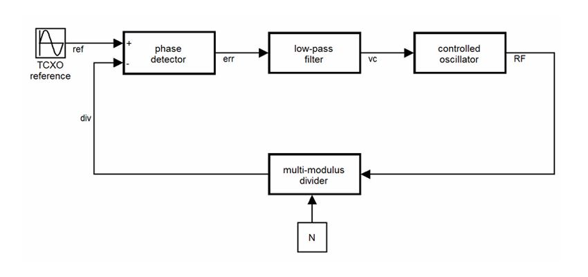
Used to synchronize the phase of two signals, the phase-locked loop (PLL) is employed in a wide array of electronics, including microprocessors and communications devices such as radios, televisions, and mobile phones. A PLL consists of a phase detector, a low-pass filter, a variable frequency oscillator, and a divider (Figure 1). Originally composed of entirely analog components, these components have been replaced over time with digital equivalents to produce an all-digital PLL (ADPLL).
ADPLLs offer several advantages over analog PLLs, particularly for microprocessor applications. ADPLLs generally have shorter lock times, and they are easier to integrate with digital components on mixed-signal integrated circuits (ICs). They also consume less area on ICs than analog PLLs, reducing die sizes and production costs. As fabrication technologies improve, ADPLLs will continue to shrink, whereas analog PLLs will not.
Designing an ADPLL can be challenging, particularly for engineers who are more familiar with analog circuit design. For example, the designer must use digital signal processing design concepts and deal with practical digital design tradeoffs such as choosing the number of bits for a signal to avoid overflow or saturation while keeping the design area small.
Creating a Linearized Model in MATLAB
In the linearized, phase-domain analytical model, each component is represented by a MATLAB transfer function. As a result, we can analyze the phase of the signal at each point in the loop. For example, we can estimate the noise at the input to the controlled oscillator and use the model to understand how that noise affects the output. This purely analytical approach lets us prototype ideas and verify functionality. It also shows us early on which component blocks pose challenges in meeting the overall design specifications.
Building a Phase-Domain Model in Simulink
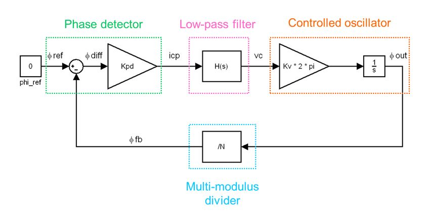
After analyzing the MATLAB model, we build the equivalent phase-domain model in Simulink, replacing the MATLAB equations with predefined blocks that implement the transfer function for each component (Figure 2). We compare the results of this model with the results of the MATLAB analytical model to verify that they agree and to understand how nonlinearities influence the output.
With the Simulink model, we can easily simulate noise, nonlinearities, and the kinds of effects seen in real devices—for example, the effects of any mismatch between the up current and the down current in the charge pump. Similarly, the Simulink model shows us how phase noise is affected by spurs generated by a sigma-delta modulator or by large variations in oscillator gain.
Unlike circuit-level simulations, which take days, we can run 10 Simulink simulations in less than two minutes. By averaging the resulting power spectral densities, we obtain a reliable estimate of the PLL design's phase noise. We also use the phase-domain model to analyze tradeoffs for individual components. For example, if we decrease the digital phase frequency detector resolution to reduce current consumption, we can see whether the resulting increase in integrated phase error and phase noise remains within the specifications.
Building a Time-Domain Model
While a phase-domain model can reveal a great deal about how a PLL will perform, it does not provide a complete picture. Time-domain models help fill in vital details, such as whether the PLL locks, and if so, how long it takes. Time-domain models also bring the design closer to the actual implementation, giving designers a more realistic view of how the PLL will perform on hardware. At the same time, because it is a behavioral model, it can be simulated in much less time than a circuit-level model. Instead of waiting weeks for a result, we can complete a 1.2-millisecond simulation with a 30-picosecond timestep in Simulink in about 15 minutes.
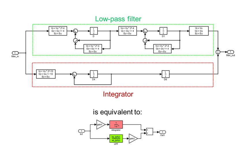
We build each component of the time-domain model separately using basic Simulink blocks (Figure 3). The component models, which start as behavioral descriptions, are increasingly refined as the high-level blocks are replaced with more hardware-accurate functional models.
For example, as a behavioral model the digital low-pass filter can be a simple Digital Filter library block with the appropriate coefficients to specify the H(z). As a functional model, the digital low-pass filter consists of D flip-flop, adder, and bit shift blocks (Figure 4).
We develop a floating-point version of the time-domain model to verify basic functionality. To prepare for implementation, we then convert each functional block to a fixed-point representation using Simulink Fixed Point™. We compare the results of the fixed-point and floating-point versions to ensure that no errors were introduced during the conversion.
In creating the model for each component, we make sure that we can easily change key parameters, such as the digital phase frequency detector gain, the digital low-pass filter coefficients, the oscillator gain, and the divider's division ratio. Parameterizing these values enables us to run parameter sweeps using a MATLAB script to initiate a series of Simulink simulations. We then post-process the simulation results in MATLAB to identify the best settings for each parameter based on the PLL's specifications.
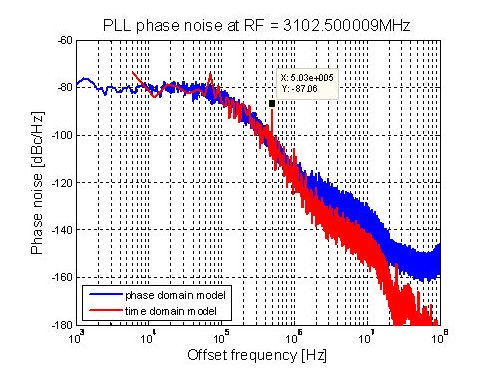
The time-domain model is most useful for understanding the transient behavior of the PLL, but it also provides some insight into phase noise performance. We plot the phase noise as a function of frequency for the phase-domain model and the time-domain model to make sure that there is broad agreement over a range of frequencies (Figure 5).
In the plot shown in Figure 5, the results are aligned for frequencies lower than 1 MHz. Above that frequency, the time-domain model has a lower phase noise. This is to be expected, as the time-domain model is less accurate at simulating noise and does not model as many real effects as the phase-domain model. The spur in the 100 kHz region of the time-domain results (called out on the graph) does not appear in the phase-domain results, a discrepancy that may indicate a problem in the model or that the design needs further investigation.
While time-domain and phase-domain simulations in Simulink reduce the need for lengthy circuit-level simulations, they do not eliminate it. Circuit-level results will still be required for further investigating a specific area of the design or unexpected results in the behavioral model.
Verifying the Hardware Implementation
After using simulation to verify the design and identify an optimal set of parameters, we're ready to use hardware prototyping on an FPGA to further verify the design before ASIC fabrication. Only blocks that can be implemented on the FPGA are verified in this way; we exclude circuits that run above frequencies the FPGA can handle. We implement the design in HDL code using Verilog, and use a Verilog simulator to run test cases that we had previously executed against the fixed-point Simulink model. We then compare the output of the two simulations bit by bit to verify the HDL implementation. Anything short of a perfect match between the results leads us to reinspect the HDL code to find the source of the discrepancy.
We then synthesize the design to create the FPGA prototype of the block to be tested. During tests in the FPGA environment, we set up probe points on the FPGA and capture the output from various points in the ADPLL. We download this data stream as a vector and import it into MATLAB. We can then verify the FPGA implementation of functional blocks in the design by comparing the captured results against the Simulink simulation results. At that point, we can deliver a verified register-transfer level (RTL) schematic of the ADPLL circuit to our customer, confident that it meets specifications.
Published 2011 - 91983v00


