Run PX4 Software-in-the-Loop Simulation with Quadcopter Plant in Simulink
This example shows you how to verify a quadcopter controller design by using Software-in-the-Loop (SITL) simulation and to simulate the quadcopter plant model in Simulink® using the UAV Toolbox Support Package for PX4® Autopilots.
Prerequisites
1. If you are new to Simulink, watch the Simulink Quick Start video.
2. You must install QGroundControl version 4.3.0 to create and upload the UAV mission used in this example.
3. If you have not done so already, install the UAV Toolbox Support Package for PX4 Autopilots. Select the installation topic appropriate for your operating system.
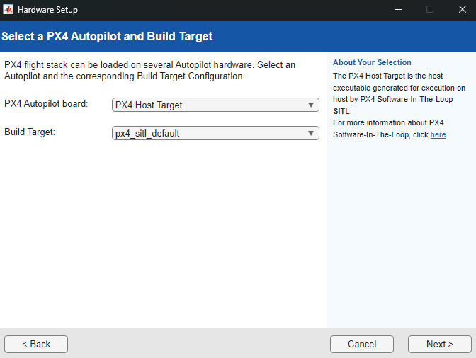
At the Select a PX4 Autopilot and Build Target step of installation, specify these options::
PX4 Autopilot board —
PX4 Host TargetBuild Target —
px4_sitl_default
4. You must start two instances of MATLAB® to run this example. Use the first instance of MATLAB to deploy the quadcopter controller model to the PX4 host target. Use the second instance of MATLAB to run the quadcopter plant model.
Getting Started in First MATLAB Instance
Launch the first instance of MATLAB. To access the Simulink model, supporting files, and project shortcuts that this example uses, open the Px4DemoHostTargetWithSimulinkPlant.prj project file.
prj = openProject("Px4DemoHostTargetWithSimulinkPlant");Copy the current folder path of the first instance of MATLAB to the clipboard.
clipboard("copy",pwd)Quadcopter Controller Model Overview
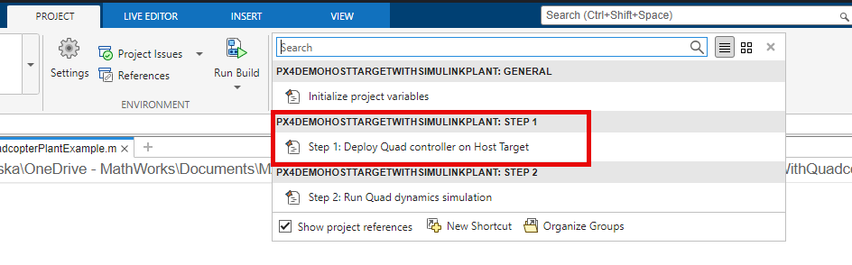
To open the Quadcopter_Controller.slx Simulink model, on the Project tab of the MATLAB Toolstrip, in the Shortcuts section, click the Step 1: Deploy Quad controller on Host Target shortcut.
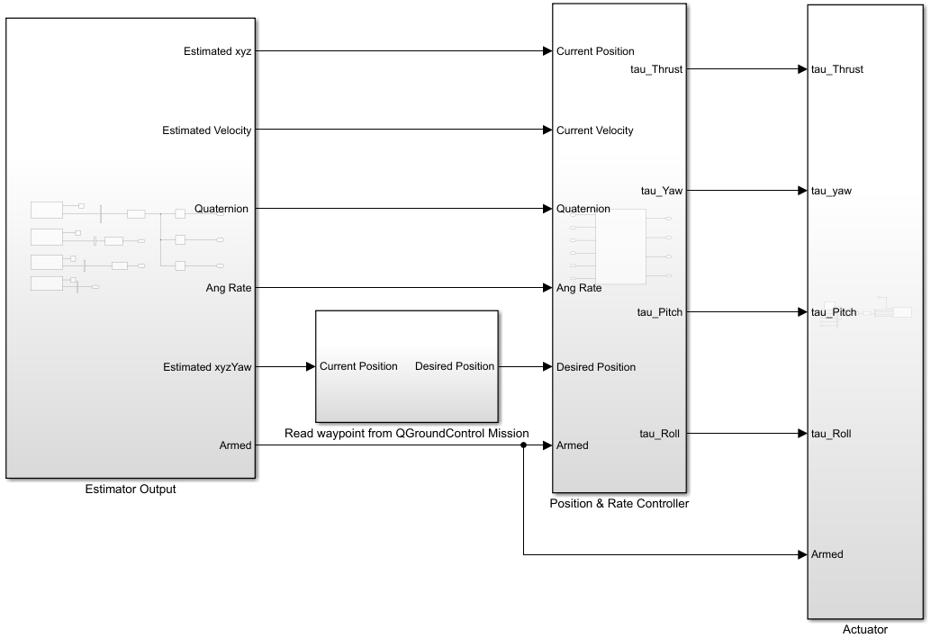
The Quadcopter_Controller.slx Simulink model consists of these subsystems:
Estimator Output— Obtains the current estimated position, attitude, angular velocity, and arm status by using PX4 uORB Read blocks subscribed to theVehicleLocalPosition,VehicleAttitude,VehicleOdometry, andActuatorArmedtopics, respectively.Read waypoint from QGroundControl Mission— Obtains the position setpoint and waypoint type of the previous waypoint, current waypoint, and the next waypoint in the mission by using a PX4 Read Position Setpoint block, which it passes to theGuidance Subsystemas input. TheGuidance Subsystemcalculates the desired position based on waypoint type, current UAV position, and waypoint position. TheRead waypoint from QGroundControl Missionsubsystem then passes the calculated desired position to thePosition & Rate Controllersubsystem as input.Position & Rate Controller— Calculates the required thrust, yaw, pitch, and roll commands for the actuators to achieve the desired positions and velocities.Actuator— Calculates the mixer matrix and sets the actuator values for the quadcopter using the PX4 Actuator Write block.
For more details on how to design a position and rate controller, see the Position Tracking for X-Configuration Quadcopter Using Rate Controller example.
Verify Model Callback Property
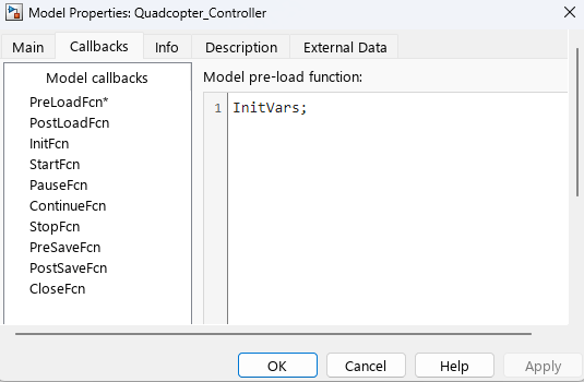
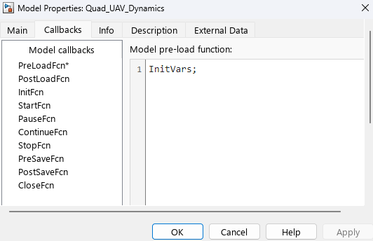
On the Simulink Toolstrip, on the Modeling tab, click Model Settings, then select Model Properties.

In the Model Properties dialog box, select the Callbacks tab. Verify that the PreLoadFcn callback function is set to InitVars, which is a helper script that initializes the quadcopter controller and dynamics model parameters.
Verify Hardware Settings
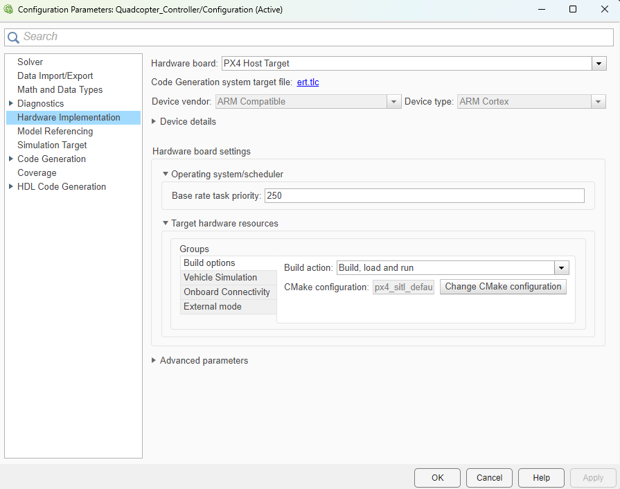
On the Simulink Toolstrip, on the Hardware tab, click Hardware Settings. In the left pane, select Hardware Implementations, and verify these options:
Hardware board specifies which PX4 autopilot to use to run the model. This example uses
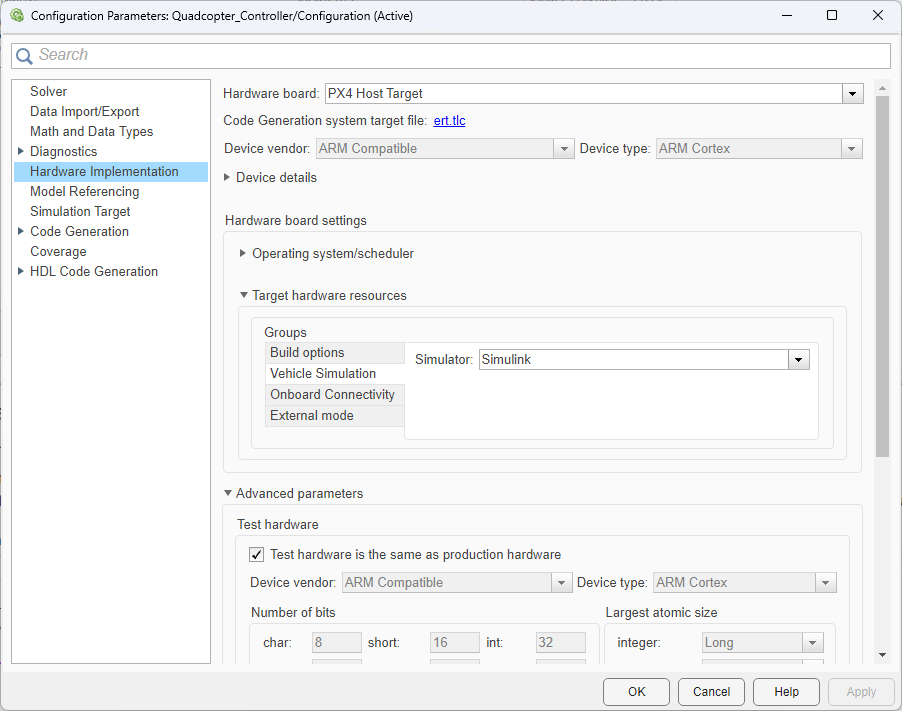
PX4 Host Target.In the Hardware board settings section, under Target hardware resources, select the Build options tab of the Groups pane. Note that Build action is set to
Build, load and run.Select the Vehicle Simulation tab of the Groups pane. Note that Simulator is set to
Simulink.
Run Quadcopter Controller Model in First MATLAB Instance
To run the Quadcopter_Controller.slx model in Monitor & Tune mode:
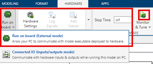
From the Simulink Toolstrip, select the Hardware tab.
Verify that the Mode section contains a Run on board button. If it instead contains a Connected IO button, click Connected IO, then Run on board (External mode).
In the Run on Hardware section, click Monitor & Tune
 .
.
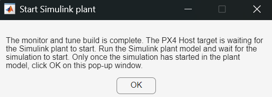
The Start Simulink plant Dialog box appears. Do not click OK until you have run the plant model in the second MATLAB instance.

Getting Started in Second MATLAB Instance
Launch a second instance of MATLAB. Then, right-click the current working directory in the address bar and paste the folder path of the first instance of MATLAB by selecting Paste and Go.
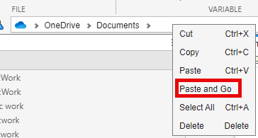
To access the Simulink model, supporting files, and project shortcuts that this example uses, open the Px4DemoHostTargetWithSimulinkPlant.prj project file.
prj = openProject("Px4DemoHostTargetWithSimulinkPlant");Quadcopter Dynamics Model Overview
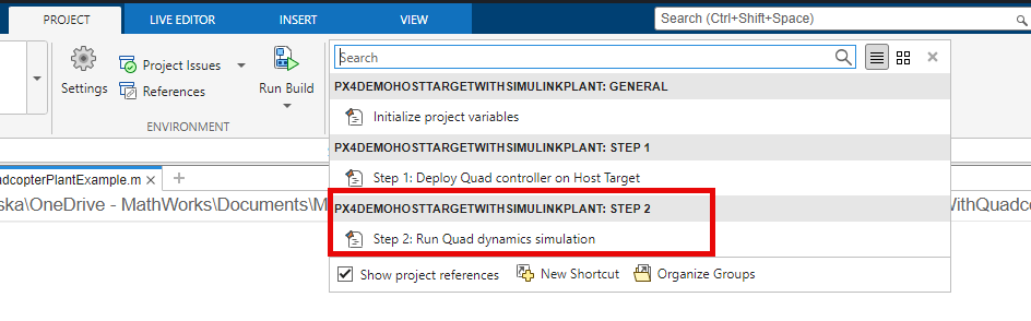
To open the quadcopter Quad_UAV_Dynamics.slx Simulink model, click the Step 2: Run Quad dynamics simulation shortcut In the Shortcuts menu of the Project pane.
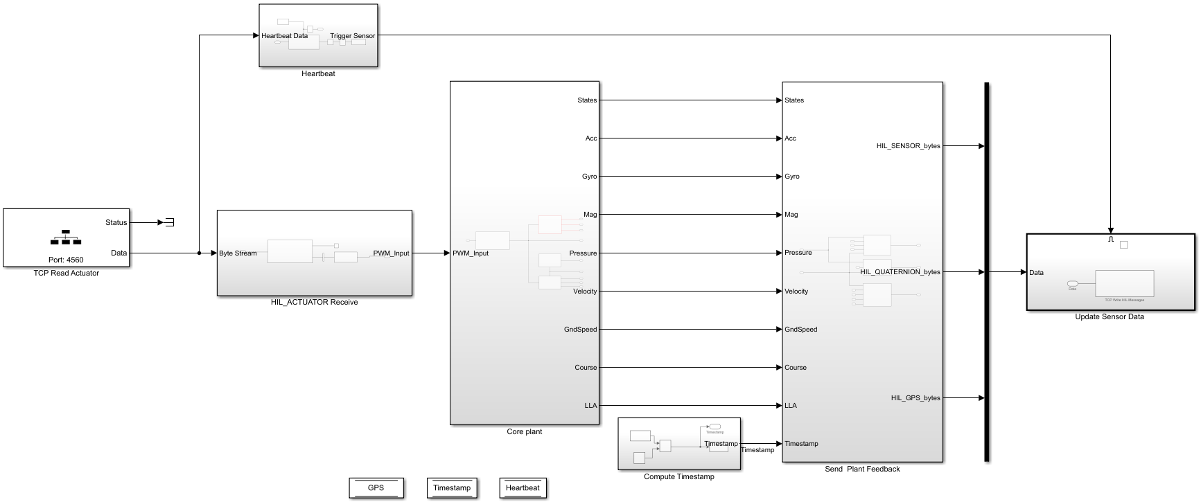
The Quad_UAV_Dynamics.slx Simulink model consists of these main blocks and subsystems:
TCP Read ActuatorMATLAB System block— Reads MAVLink messages sent by the PX4 host target.HIL_ActuatorReceivesubsystem — Extracts theHIL_ACTUATOR_CONTROLSMAVLink message by using a MAVLink Deserializer block.Core plantsubsystem — Calculates the quadcopter forces and moments, and uses the 6DOF (Euler Angles) (Aerospace Blockset) block to calculate the quadcopter states. The subsystem uses the calculated states as ground truth for the IMU, barometer, and GPS sensor models to calculate the estimated states, which it passes to theSend Plant Feedbacksubsystem as input.Send Plant Feedbacksubsystem — Creates theHIL_SENSOR,HIL_GPS, andHIL_STATE_QUATERNIONMAVLink messages using MAVLink Serializer blocks.Update Sensor Datasubsystem — SendsHIL_SENSOR,HIL_GPS, andHIL_STATE_QUATERNIONMAVLink messages to the PX4 host target.
For more details on how to use a plant model designed in Simulink for SITL simulation, see the Integrate Simulator Plant Model Containing MAVLink Blocks with Flight Controller Running on PX4 Host Target example.
Verify Model Callback Property
On the Simulink Toolstrip, on the Modeling tab, click Model Settings, then select Model Properties.
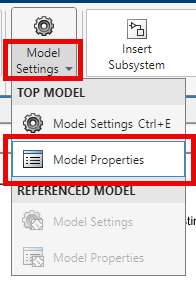
In the Model Properties dialog box, select the Callbacks tab. Verify that the PreLoadFcn callback function is InitVars.
Verify Simulation Pacing
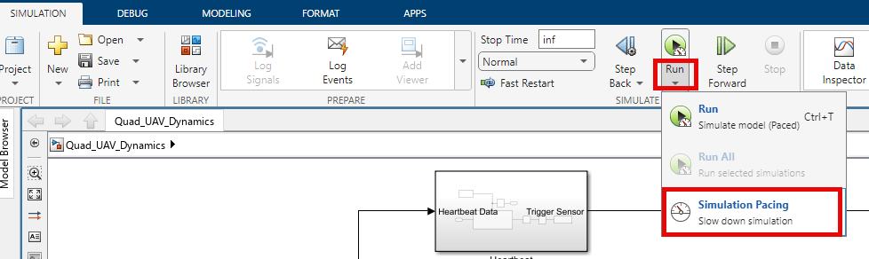
On the Simulink Toolstrip, on the Simulation tab, click Run, then Simulation Pacing.
In the Simulation Pacing Options dialog box, verify that the Enable pacing to slow down simulation option is selected and Simulation time per wall clock second is set to 1, which ensures that the model runs at a rate of approximately 1 second of simulation time per second of clock time.
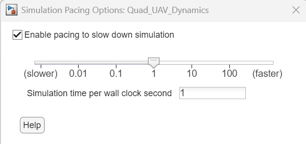
For more information on simulation pacing, see Simulation Pacing Options (Simulink).
Run Quadcopter Plant Model in Second MATLAB Instance
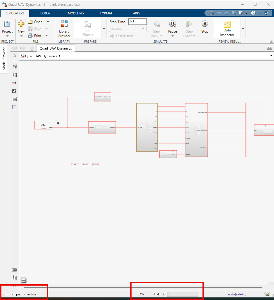
On the Simulation tab of the Simulink Toolstrip, select Run ![]() to start the
to start the Quad_UAV_Dynamics.slx model. Verify that the model is running by examining the status bar.
Once the plant model is running, return to the first MATLAB instance and, in the Start Simulink plant dialog box, click OK.
Launch and Connect QGroundControl
Launch QGroundControl. If you run this example on a Linux machine, QGroundControl automatically connects to the Simulated UAV.
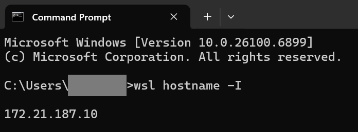
If you run this example on a Windows machine, you must first connect QGroundControl to the Simulated UAV. First, obtain the IP address of Windows Subsystem for Linux (WSL) prior to connecting QGroundControl. To find the IP address of WSL, open the Windows Command Prompt, then enter wsl hostname -I. This image shows the IP address of the WSL as 172.21.187.10.
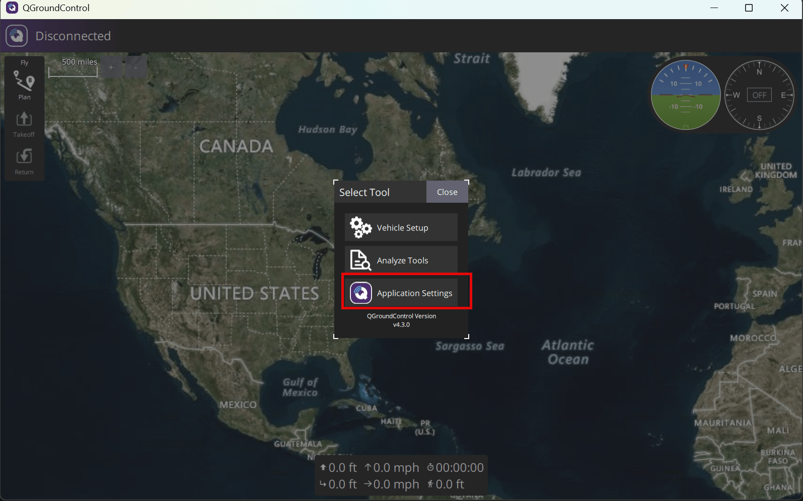
Then, at the top of the QGroundControl interface, next to Disconnected, click the QGroundControl logo to open the Select Tool dialog box, then click the Application Settings.
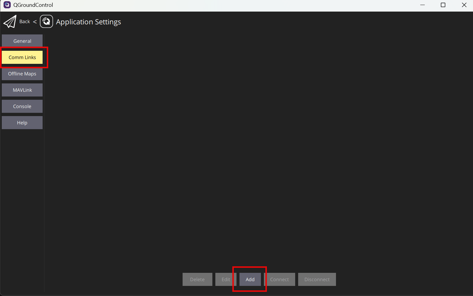
In the Application Settings menu, click Comm Links, then click Add
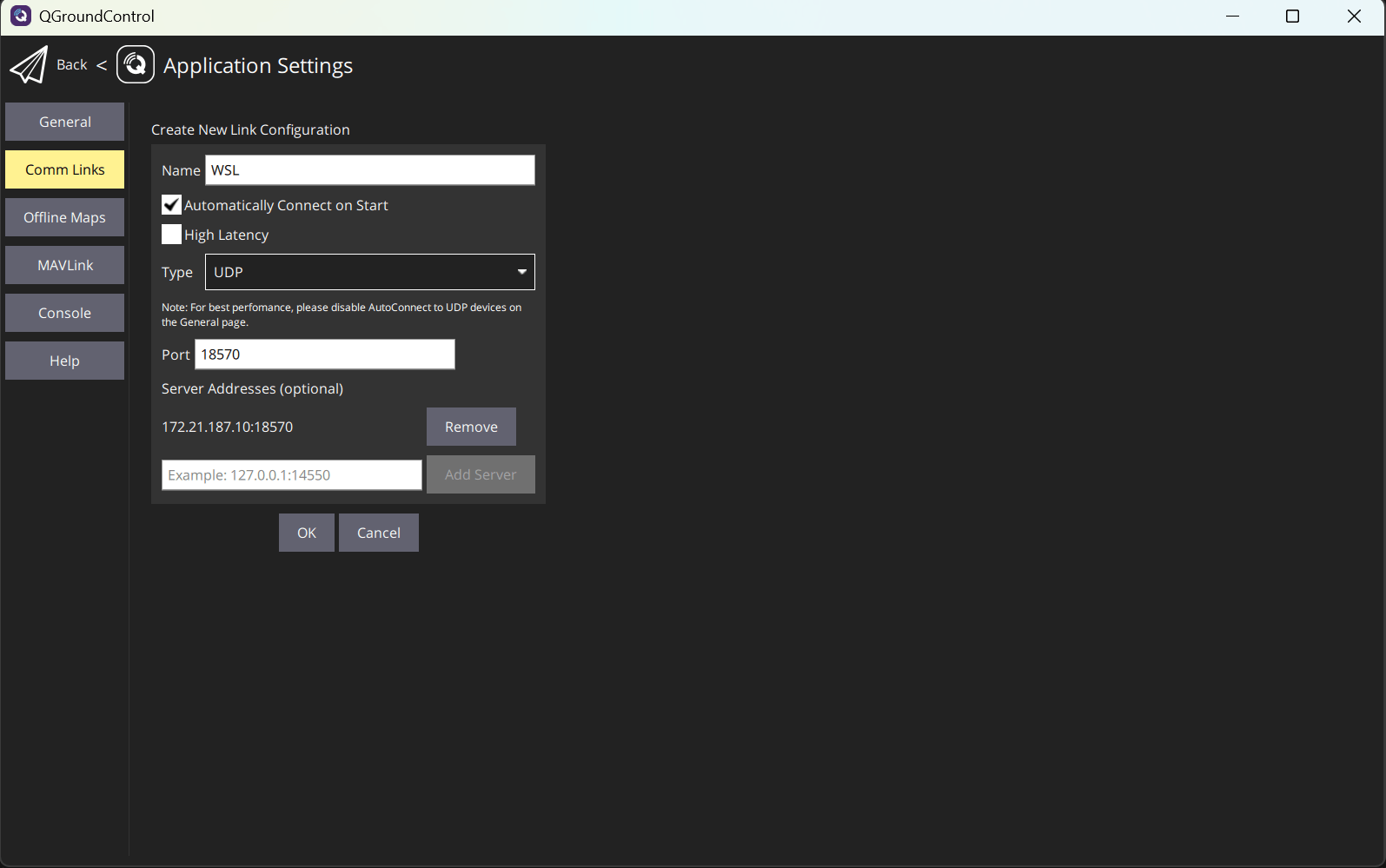
In the Create New Link Configuration menu:
Add a new name for the link, such as
WSL.Select Automatically Connect on Start.
Set Type to UDP.
Specify Port as
18570as documented in the PX4 documentation.If you run this example in a Windows environment, in the Server Addresses section, enter the IP address of your WSL, then a colon, and lastly the port number. For example:
172.21.187.10:18570. Then, click Add Server.
To store the changes, click OK.
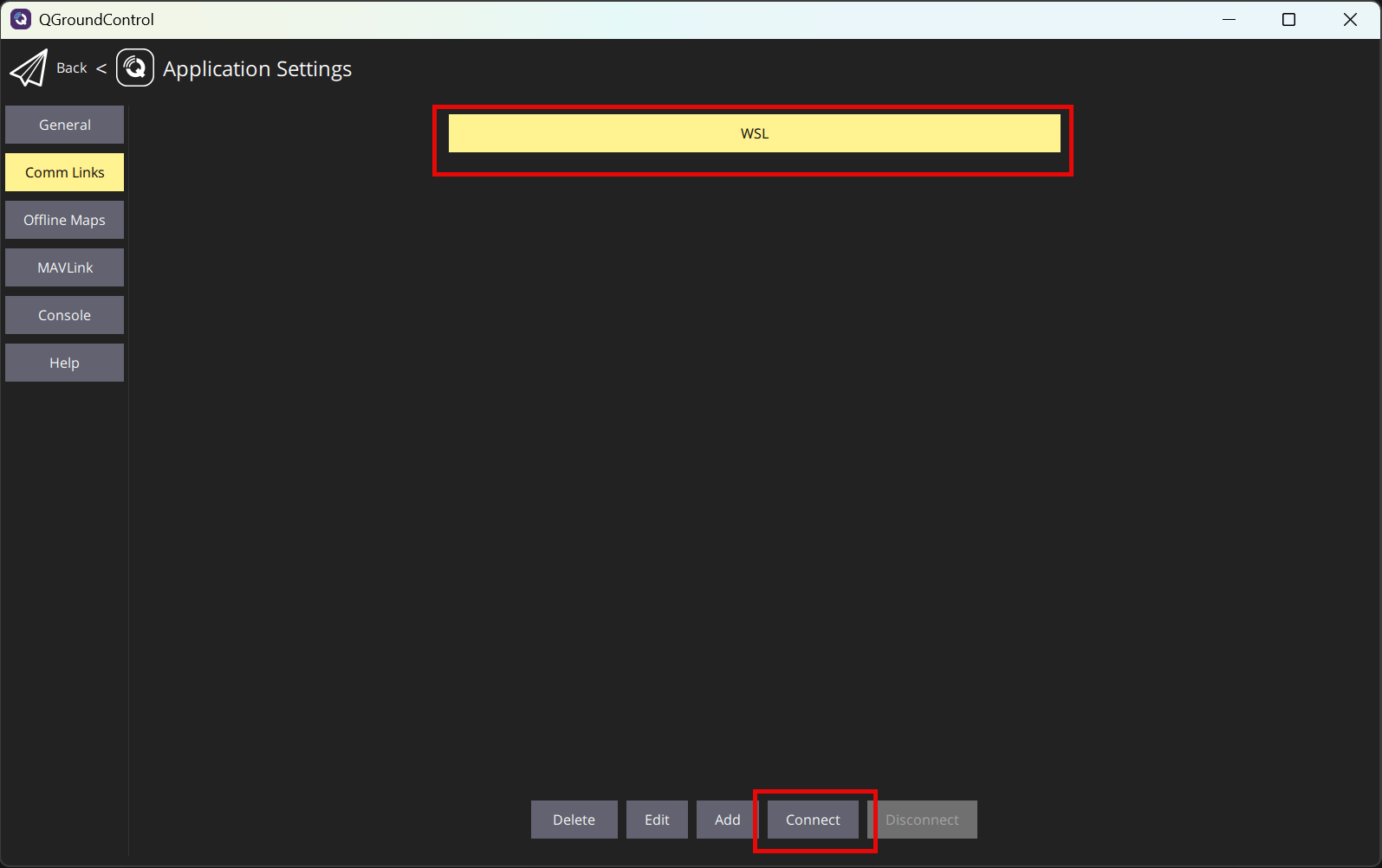
Select the link that you created, and then click Connect to start the connection.
Create and Upload Mission
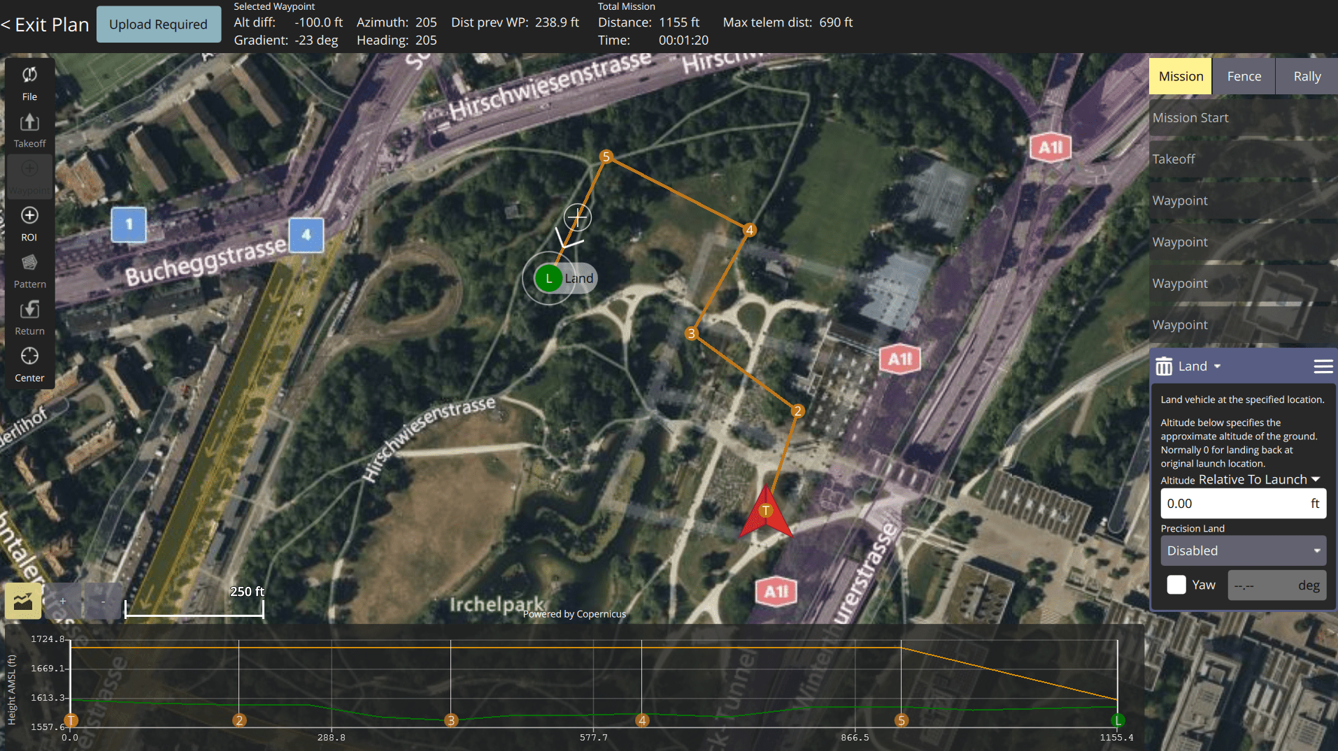
At the top of the QGroundControl interface, next to Connected, click the QGroundControl logo, and then select Plan Flight to create a custom mission. By default, the Guidance Subsystem located in the Read waypoint from QgroundControl Mission subsystem of the Quadcopter_Controller model supports only these types of mission commands:
Takeoff
Land
Waypoint
For more information on how to create a custom mission in QGroundControl, see Plan View.
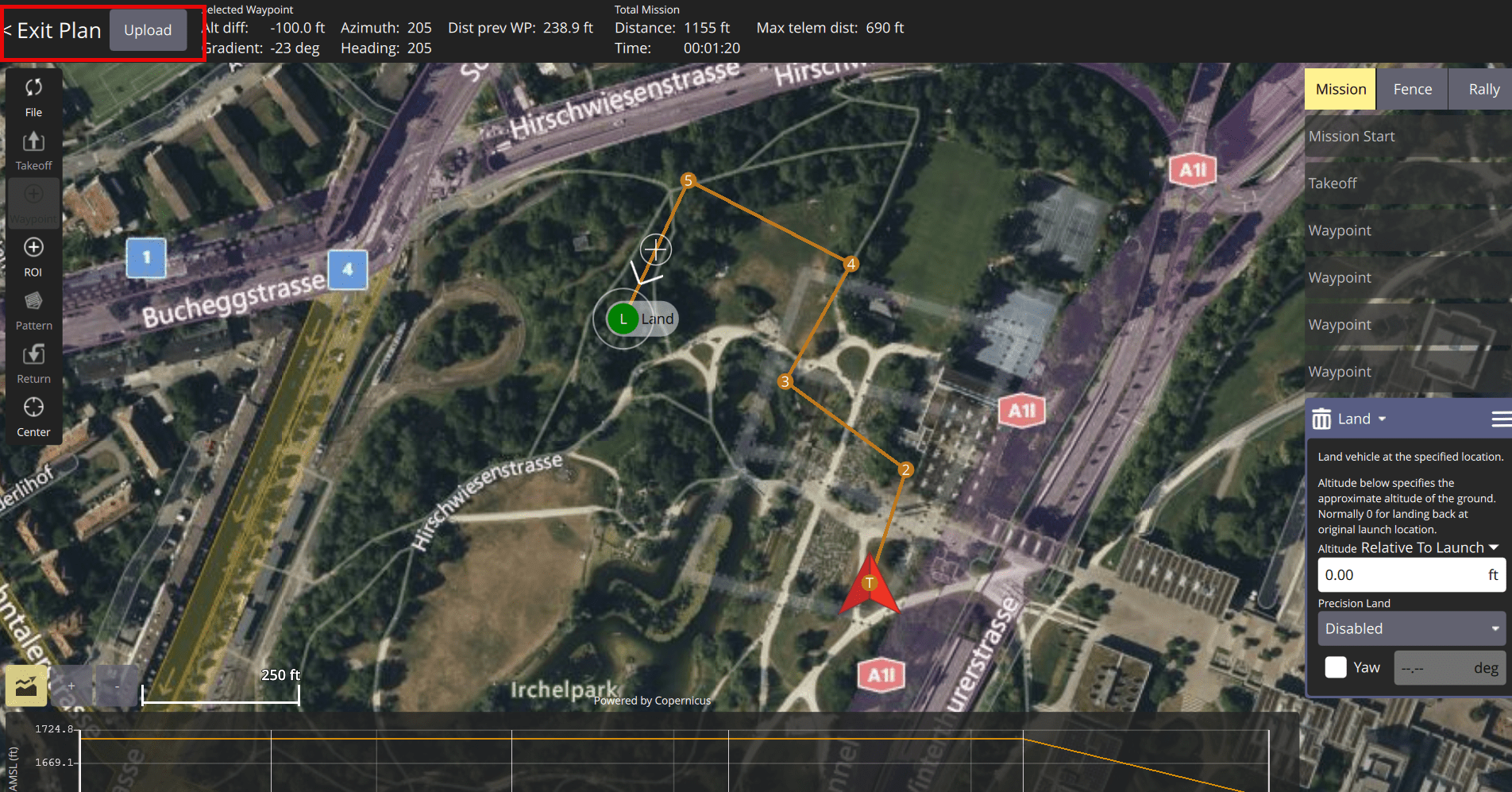
Once you have created your mission, upload it by clicking Upload Required, then Upload. Return to the Fly View by clicking Exit Plan.
Start Mission
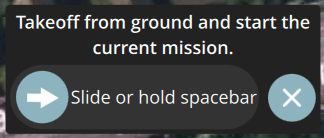
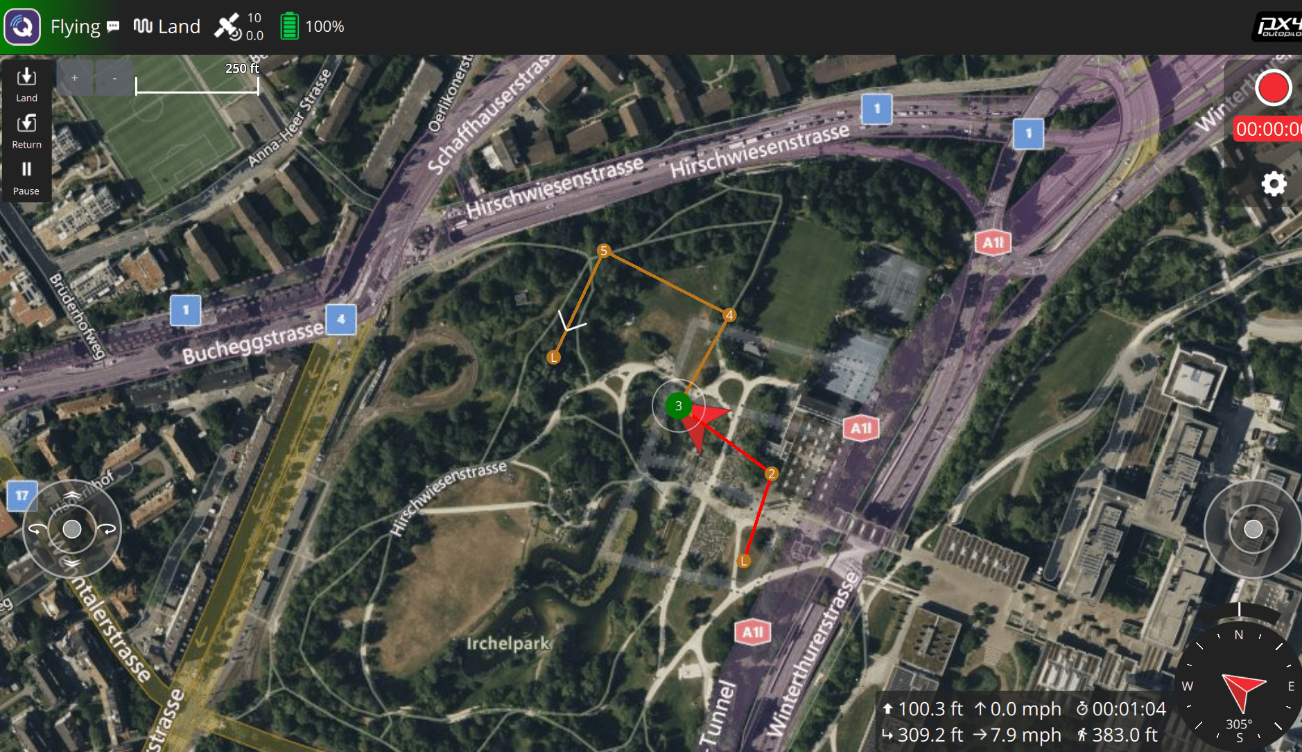
In the Fly View, start the mission by using the slider or holding the spacebar.
The UAV now flies through the mission using the plant and controller models from Simulink.
To end the simulation after the mission has finished, first stop the Quadcopter_Controller.slx Simulink model, then stop the Quad_UAV_Dynamics.slx Simulink model.
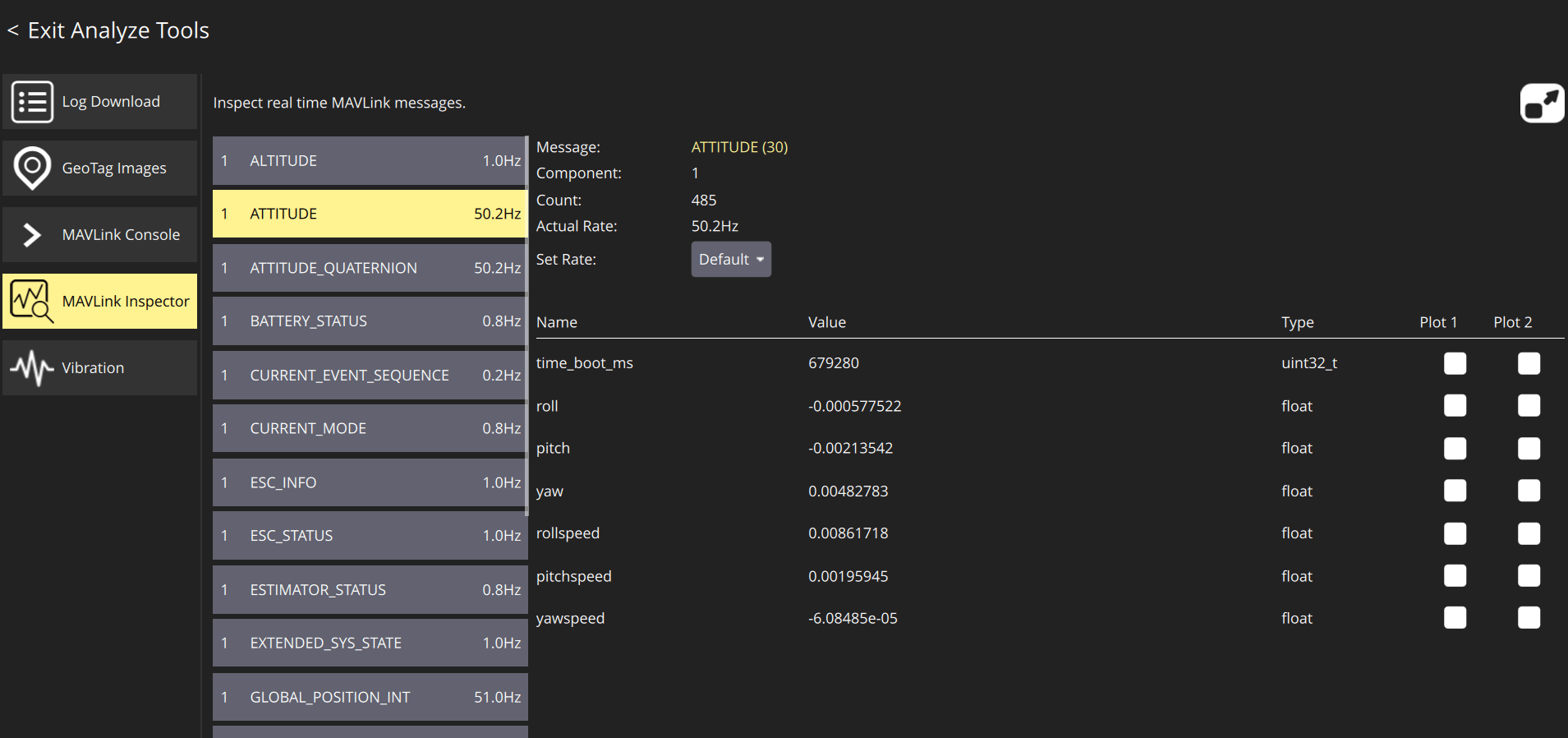
Verify Simulation Update Rate
To check if the simulation has a sufficient update rate, in QGroundControl, open the MAVLink Inspector while the mission is running, then verify that each of these MAVLink messages has an update rate of approximately 50 Hz or better:
ATTITUDEATTITUDE_QUATERNIONGLOBAL_POSITION_INTLOCAL_POSITION_NEDSERVO_OUTPUT_RAW
If any of these messages has an update rate of less than 50 Hz, your computer might not meet the hardware requirements for running the simulation.