Model Reference Support for Arduino Driver Blocks in Simulink
A model reference is a reference to another model using a Model block. These references create model hierarchy. Each referenced model has a defined interface that specifies the properties of its inputs and outputs. The defined interface makes the behavior of the referenced model independent of its context in the model hierarchy. For simulation and code generation, a referenced model executes like a single block, or atomic unit, when the parent model executes. Model references are ideal for code reuses, unit testing, parallel builds, and large components. They can also reduce file contention and merge issues. For more information, see Model References.
In Simulink® Support Package for Arduino® Hardware, you can now use all the driver blocks from Simulink Arduino library inside model reference expect for the Hardware Interrupt SAMD block.
Reference Existing Models
A model becomes a referenced model when a Model block in another model references it. Any model can function as a referenced model and can continue to function as a separate model.
Follow these steps to reference an existing model in another model.
Add the folder containing the model you want to reference to the MATLAB® path. For more information, see What Is the MATLAB Search Path?
In the Configuration Parameters dialog box, set Total number of instances allowed per top model to any one of these options.
One— Use the model at most once in a model hierarchy.Multiple— Use the model more than once in a model hierarchy.
Create an instance of the Model block in the parent model. The new block is initially unresolved because it does not specify a referenced model.
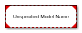
Double click the unresolved Model block to open the Block Parameters dialog box and enter the name of the referenced model in the Model name field.
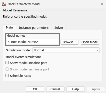
Click OK. If the referenced model contains root-level inputs or outputs, the Model block displays the corresponding input and output ports. For more information, see Reference Existing Models.
Considerations for Model Referencing
Consider scheduling only from top models.
Make sure all driver blocks use the same configuration parameters across models. If the parameters differ, the block may exhibit undefined behavior as Simulink cannot determine which configuration settings to apply to the model.
When a function block is present at the top level of a referenced model, standalone code generation for the child model is not supported. In such cases, code must be generated from the parent model that references it.
Only one instance of the referenced model is allowed per top-level model.
For referenced models, if the maximum identifier length is insufficient to ensure unique global identifiers across models, navigate to Configuration Parameters > Diagnostics and set Insufficient maximum identifier length to
None.When naming the top model and its referenced models, make sure that the first 31 characters of each model name are unique. If the names share the same initial 31 characters, a compilation error may occur during code generation. This is because the generated code uses the first 31 characters for naming global variables, which can lead to naming conflicts. To avoid such issues, use concise and distinct names for each model, especially when working with model referencing and code generation.
Create Data Dictionary and Migrate Model
Create data dictionary to store model parameters and shared configuration parameter references. This approach promotes consistency and reusability across both parent and referenced (child) models. For basic information about data dictionaries, see What Is a Data Dictionary?.
Follow these steps to create a data dictionary and migrate a model.
Right click on the model canvas and select Model Properties from the menu.
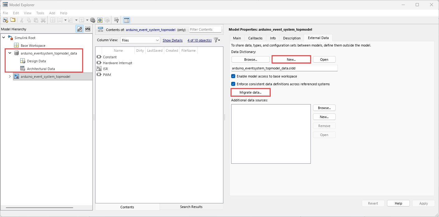
In the Model Properties dialog box, go to the External Data tab and click New to create a data dictionary.
Enter a name for the data dictionary and click Apply.
In the Link Model to Data Dictionary dialog box, click Change all models.
In the Model Properties dialog box, click Migrate data.
Click Migrate in response to the message about copying referenced variables.
(Optional) Clear Enable model access to base workspace and click OK.
To open the dictionary, in the Simulink Editor, click the model data badge
 in the bottom left corner, then click
External Data. To inspect the contents of the
dictionary, in the Model
Explorer app, in the Model Hierarchy pane,
expand the dictionary node.
in the bottom left corner, then click
External Data. To inspect the contents of the
dictionary, in the Model
Explorer app, in the Model Hierarchy pane,
expand the dictionary node.
Convert Configuration Sets to References and Apply in Simulink Models
All models must use the same configuration parameters referred to by the driver blocks. If these parameters differ between models, the behavior becomes undefined because the block may use any of the available configurations. To avoid this, create configuration parameter references and use the same reference in both reference and top models. This approach makes sure that any change to the parameters is automatically reflected across all models thus, maintaining consistency and predictability.
Follow these steps to convert the active configuration set to a configuration reference.
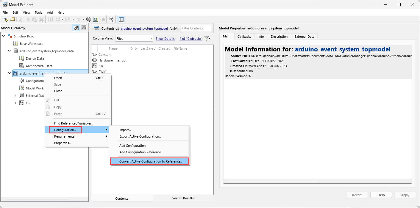
Open Model Explorer.
In the Model Hierarchy pane, right click on the model name and select Configuration > Convert Active Configuration to Reference.
In the Convert Configuration to Reference dialog box, name the configuration reference and click OK.
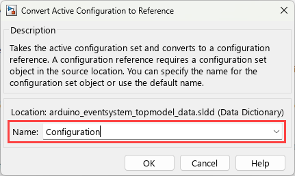
The associated
slddfile is selected to create a reference configuration set. This configuration reference allows multiple models to use the same configuration set.To view the newly created reference configuration, in the Hardware tab of the model, in the Prepare section, select Hardware Settings.
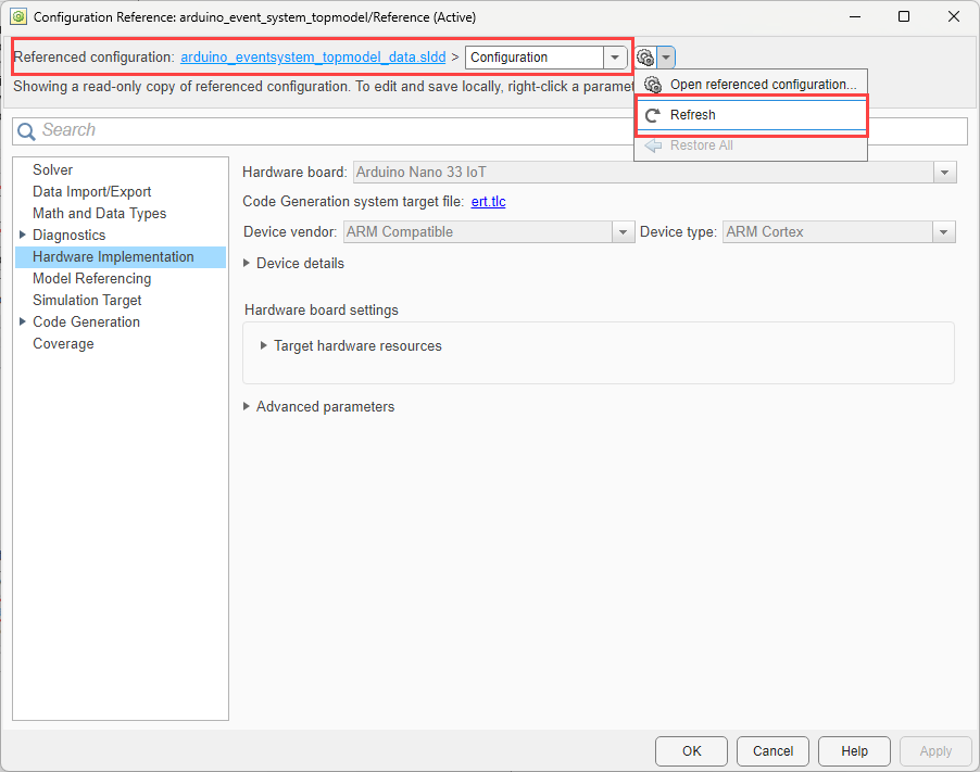
You can modify the reference configuration and share a configuration with multiple models. For more information, see Share a Configuration with Multiple Models.
In the Get Started with Arduino SAMD Event System Using PWM and ADC Peripherals example, you can use the predefined synchronous referenced model.
Configure Reference Model for Synchronous and Asynchronous Task
When using reference models with Arduino in Simulink, task scheduling is determined by the top model. If the reference model contains only synchronous tasks, its execution is controlled by the sample time specified in the top model. The reference model will run at the rate it is called from the parent model.
If the reference model includes asynchronous tasks, you must take additional steps to ensure these tasks are properly triggered from the top model. For example, you may need to use external interrupts or specific trigger mechanisms supported by Arduino to coordinate the execution of asynchronous tasks.
This section explains how to configure a reference model for Arduino when it contains asynchronous tasks, ensuring that all tasks are
correctly scheduled and triggered from the top model. To further demonstrate this
workflow, the Get Started with Arduino SAMD Event System Using PWM and ADC Peripherals example
contains a preconfigured top model
(arduino_event_system_topmodel.slx), a reference model
(adc_synchronization_referencemodel.slx), and an SLDD file
(arduino_eventsystem_topmodel_data.sldd).
To open the preconfigured top model, run this command in the MATLAB Command Window.
openExample('arduino/GetStartedArduinoSAMDEventSystemUsingPWMADCPeripheralsExample', 'supportingFile', 'arduino_event_system_topmodel.slx')Navigate to the
adc_synchronization_referencemodelsubsystem where you would configure the reference model. Verify that the Asynchronous Task Specification (Simulink Coder) block is added and it matches the task priority of the Hardware Interrupt SAMD block triggering it in the top model.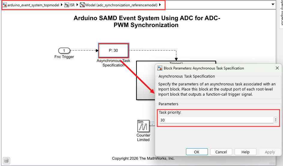
Make sure of the following points in the Simulink models for correct and predictable execution of both synchronous and asynchronous tasks in the model hierarchy.
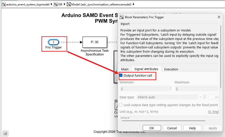
Correct triggering of asynchronous tasks — Enable Output function call on the Inport that triggers the asynchronous task. This makes sure that the reference model or subsystem responds properly to external events or interrupts.
Consistent execution rates for periodic tasks — Match the periodic rate in the reference model (
adc_synchronization_referencemodel.slx) to the top model (arduino_event_system_topmodel.slx). This makes sure that the synchronous tasks run at the intended frequency and avoids timing mismatch.Proper scheduling of tasks — Scheduling synchronous tasks through the base rate and asynchronous tasks through interrupts. This makes sure that each type of task executes using the most appropriate and reliable mechanism, reflecting real hardware behavior and preventing conflicts or missed executions.
In the top model (
arduino_event_system_topmodel.slx), right click onadc_synchronization_referencemodel. Select Block Parameters. In the Main tab, select Schedule rates. This option adds an inport with the scheduling icon. You can use this to configure it to be triggered by a periodic task, such as a function-call generator in this example.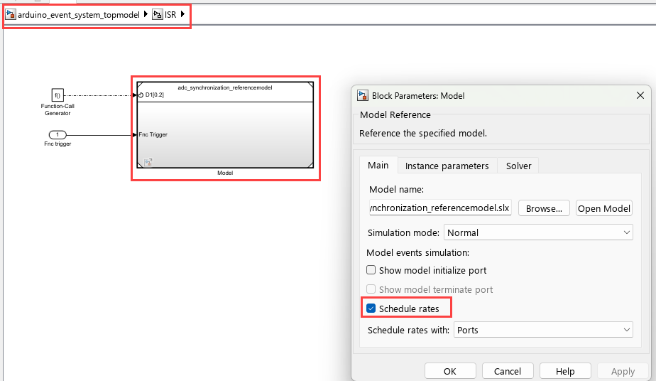
The output trigger from Hardware Interrupt SAMD block, is passed as an input to the previously configured asynchronous port in the reference model (
adc_synchronization_referencemodel.slx). With these configurations, the reference model with both synchronous and asynchronous task can be triggered from the top model (arduino_event_system_topmodel.slx).
Note
With asynchronous task specification, independent code generation from the reference model is not supported.
See Also
Get Started with Arduino SAMD Event System Using PWM and ADC Peripherals | Inport