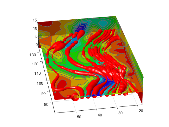
ストリーム チューブの発散の表示
表示できるストリーム チューブ
ストリーム チューブは流線と似ていますが、情報を表すために使用可能なもう 1 つの次元を与える幅をもっています。
既定の設定では、MATLAB® はチューブの幅によってベクトル場の発散を表します。各チューブの頂点に対して幅を定義することが可能で、それにより他のデータ幅に写像することができます。
この例は、以下の手法を使用しています。
ストリーム チューブは、流れの方向と
windデータ セットのベクトル場の発散を表します。風速を表すために色付けされたスライス平面は、等高線を重ねて視覚状態を強調します。
入力には、ボリューム データの座標、ベクトル場の要素、ストリーム チューブの開始位置が含まれます。
1. データの読み込みと必要な値の計算
まず、データを読み込んで、プロットの作成に必要な値を計算します。これらの値には、次のものがあります。
スライス平面の位置 (最大
x、最小y、高度に対する値)ストリーム チューブの開始位置の最小値
x風速 (ベクトル場の大きさ)
load wind
xmin = min(x(:));
xmax = max(x(:));
ymin = min(y(:));
alt = 7.356; % z value for slice and streamtube plane
wind_speed = sqrt(u.^2 + v.^2 + w.^2);
2. スライス平面を描く
スライス平面を描画し (slice)、surface プロパティを設定して滑らかに色付けされたスライスを作成します。hsv colormap から 16 色を使用します。
hslice = slice(x,y,z,wind_speed,xmax,ymin,alt);
set(hslice,'FaceColor','interp','EdgeColor','none')
colormap hsv(16)
3. スライス平面への等高線の追加
スライス平面に等高線を付加します (contourslice)。等高線の間隔を調整して、次のようにラインがスライス平面内の色の境界と一致するようにします。
climを呼び出して、現在の色の範囲を取得します。R2022a より前:
caxisを使用します。その構文と引数はclimと同じです。contoursliceが使用する内挿法をlinearに設定してsliceが使用する既定の設定と一致させます。color_lim = clim; cont_intervals = linspace(color_lim(1),color_lim(2),17); hcont = contourslice(x,y,z,wind_speed,xmax,ymin,... alt,cont_intervals,'linear'); set(hcont,'EdgeColor',[.4 .4 .4],'LineWidth',1)
4. ストリーム チューブの作成
meshgrid を使用して、ストリーム チューブに対する開始位置の配列を作成します。これは x の最小値からはじまり、y は 20 から 50 の範囲で z 方向の 1 つの平面にあります (スライス平面のうちの 1 つに対応)。
ストリーム チューブ (streamtube) は、指定した位置に描画され、既定の幅の 1.25 倍にスケーリングされ、発散 (幅) の変動を強調します。ベクトル [1.25 30] の 2 番目の要素は、チューブの範囲に沿ったポイント数を指定します (既定の設定は 20 です)。滑らかな外観のチューブを維持するために、チューブのサイズが大きくなるに連れて、この値を増加させる必要があります。
データの縦横比 (daspect) を streamtube を呼び出す前に設定します。
ストリーム チューブは、surface オブジェクトなので Surface プロパティの設定によりその外観をコントロールすることができます。次の例は、Surface プロパティを設定して明るい光源と赤色の表面を与えます。
[sx,sy,sz] = meshgrid(xmin,20:3:50,alt);
daspect([1,1,1]) % set DAR before calling streamtube
htubes = streamtube(x,y,z,u,v,w,sx,sy,sz,[1.25 30]);
set(htubes,'EdgeColor','none','FaceColor','r',...
   'AmbientStrength',.5)
5. 表示の定義
表示を定義し、ライティングを追加します (関数 view、関数 axis、関数 volumebounds、Projection、関数 camlight)。
view(-100,30)
axis(volumebounds(x,y,z,wind_speed))
set(gca,'Projection','perspective')
camlight left
