このページの内容は最新ではありません。最新版の英語を参照するには、ここをクリックします。
バルブとオリフィス
以下のブロックを使用して、等温液体ドメインのオリフィス、バルブ、バルブ アクチュエータ、およびバルブとオリフィスに関連付けられた力をモデル化します。
Simscape ブロック
トピック
- Modeling Directional Valves in Simscape Fluids
Selecting and parameterizing directional control valves in Simscape™ Fluids™.
- Building a Custom Valve
Model a custom valve with orifice blocks.
- Parameterize an M-Way N-Position Valve
Use a data sheet to parameterize an M-Way N-Position Valve (IL).
注目の例
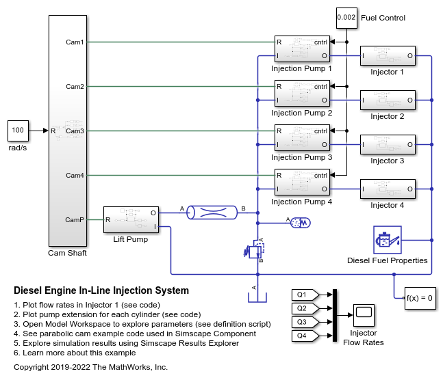
Diesel Engine In-Line Injection System
An in-line multi-element diesel injection system. It consists of a cam shaft, a lift pump, four in-line injection pumps, and four injectors.

2 つの油圧モーターを制御するプライオリティ バルブ
この例では、3 方向の圧力補償流量制御バルブを示します。このバルブは、圧力補償流量制御バルブの出口に接続されたメイン油圧モーターを通る流量を一定に保ちます。プライオリティ バルブとして機能し、事前設定された角速度を維持するための十分な流体がメイン油圧モーターに供給されると、余剰流量を補助油圧モーターに回します。補助モーターは、メイン油圧モーターに電力を供給するための十分な流量がないときは完全に停止しています。
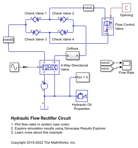
油圧流量整流器回路
この例では、4 つのチェック バルブと 1 つの流量制御バルブをもつ流量整流器回路を示します。これを使用すると、両方向の流体の流れを単一の流量制御バルブで制御できます。ダイオードで実装される Graetz 回路と同様、流量が流量制御バルブを常に同じ方向で通過するようにチェック バルブが配置されます。Orifices サブシステムにあと 2 つ、流量が通過するオリフィスを流れの方向に応じて選択するために使用されるチェック バルブがあります。
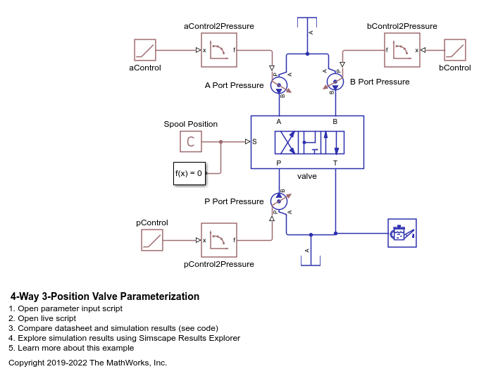
4 方向 3 位置バルブのパラメーター化
この例では、テスト ハーネスを使用して 4 方向 3 位置バルブのパラメーター化とテストを行う方法を示します。ブロックとデータの出流量を比較してテスト ハーネスを検証するために、この例にはプロット スクリプトが用意されています。また、パラメーター化とテスト ハーネス ワークフローについて詳しく説明するために、この例ではライブ スクリプトも提供されています。
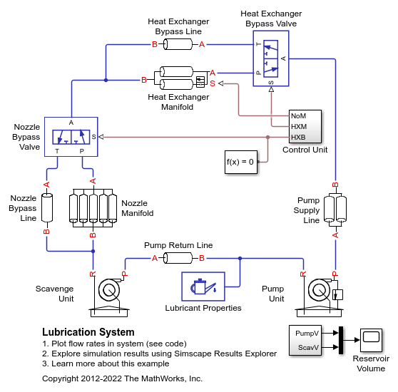
潤滑システム
この例では、遠心ポンプにより供給される簡略化したバージョンの潤滑システムを示します。このシステムは 5 つの主要ユニットで構成されます。ポンプ ユニット、スカベンジ ユニット、熱交換器マニホールド、ノズル マニホールド、制御ユニットです。ポンプ ユニットとスカベンジ ユニットは、どちらも遠心ポンプを中心に構築されます。スカベンジ ユニットは、ノズルから排出される流体を回収してポンプ ユニットのタンクに送り返します。制御ユニットは、局部抵抗として表される熱交換器またはノズル ブロックのいずれかをバイパスするコマンドを生成します。実際のシステムでは、これらのコマンドは潤滑キャビティに搭載された温度センサーによって生成されます。
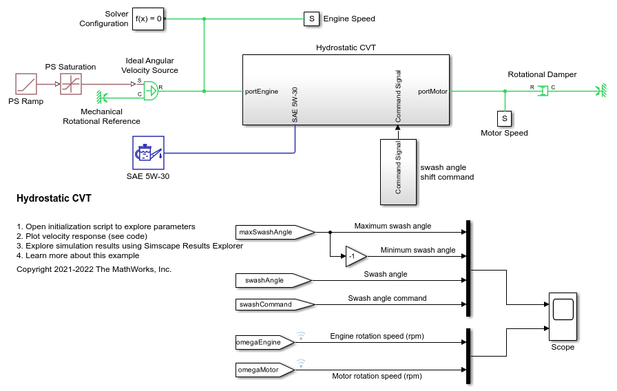
Hydrostatic CVT
Model, parameterize, and test a hydrostatic continuously variable transmission (CVT) with a swash angle shift command. When you run the plot function, it generates a comparison plot between the engine and the achieved rotational velocity in the hydraulic axial piston motor with respect to the time. Construction and agricultural equipment manufacturers use these transmissions.
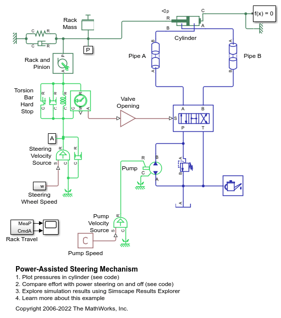
パワー ステアリング機構
この例では、簡略化したバージョンのパワー ステアリング機構を示します。この油圧作動システムには、複動式油圧シリンダー、4 方向バルブ、固定容量型ポンプ、および圧力安全バルブが含まれています。ステアリング ラックは、バネとダンパーでモデル化される負荷に対して動作します。
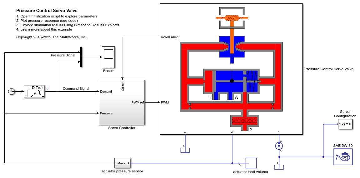
Pressure Control Servo Valve
Model, parameterize, and test a pressure control servo valve with a closed loop control. This example also generates a comparison plot between the commanded and the achieved pressure in the actuator with respect to the time. This valve provides a precise and fast control of the pressure in the actuator with a very small electrical signal to the torque motor. These valves are used in the aerospace industry and the automotive industry for the safety critical applications.
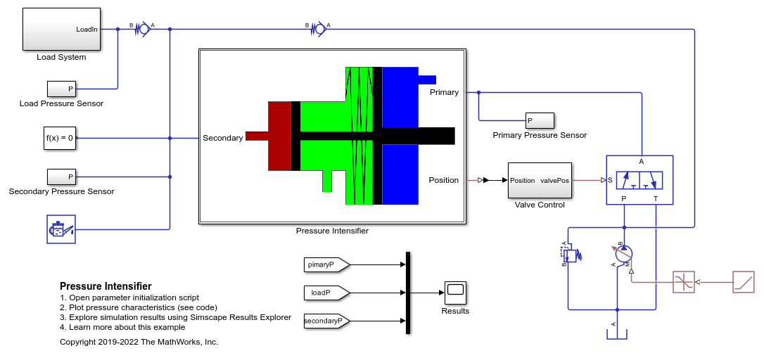
Pressure Intensifier
Model, parameterize, and test a pressure intensifier.

Hydraulic Clutch System
Model, parameterize, and test a hydraulic clutch system. The model is used to generate the plot of the engine and the transmission system speeds during a declutching and clutch re-engaging scenario.

圧力制御ソレノイド
この例では、圧力制御ソレノイド バルブをモデル化、パラメーター化、およびテストする方法を示します。この例では、加えられるソレノイド力と結果として生じるアクチュエータ端子圧力の関係を示すプロットも生成します。

デュアル カウンターバランス バルブを備えた油圧アクチュエータ
この例では、4 方向バルブで制御されるアクチュエータに支配的な負荷がかかる場合を示しています。このような場合、方向制御バルブが中立位置にあるときは、カウンターバランス バルブを使用して負荷によるクリープを防ぐ必要があります。中立位置では、方向制御バルブは圧力端子 P をブロックしながら端子 A と端子 B をタンクに接続します。カウンターバランス バルブは流れがタンクに戻るのを防ぐため、アクチュエータは所定の位置に保たれます。
油圧流量整流器回路
この例では、4 つのチェック バルブと 1 つの流量制御バルブをもつ流量整流器回路を示します。これを使用すると、両方向の流体の流れを単一の流量制御バルブで制御できます。ダイオードで実装される Graetz 回路と同様、流量が流量制御バルブを常に同じ方向で通過するようにチェック バルブが配置されます。Orifices サブシステムにあと 2 つ、流量が通過するオリフィスを流れの方向に応じて選択するために使用されるチェック バルブがあります。
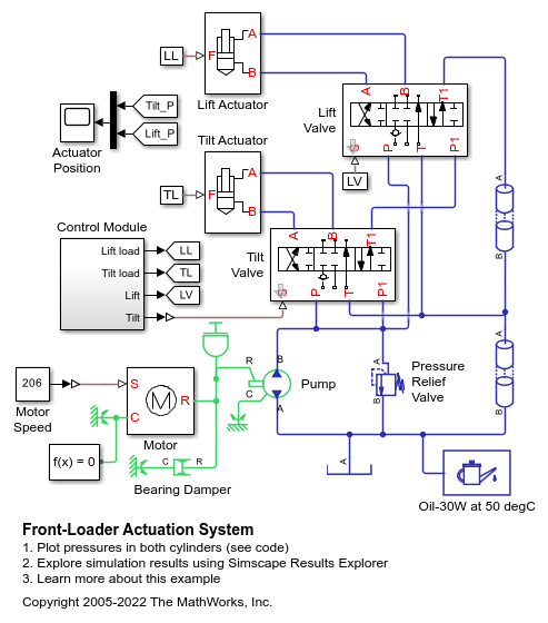
フロントローダー作動システム
この例では、リフト シリンダーとティルト シリンダーで構成される簡略化したバージョンの作動システムを示します。各シリンダーは、オープン センター型の 6 方向 3 位置方向制御バルブによって制御されます。バルブは、両方のコマンド レバーが中立位置にあるときにシステムのポンプが無負荷になるように、無負荷側の分岐に直列に接続されます。ティルト コマンドまたはリフト コマンドのいずれかが適用されると、無負荷経路は閉じます。

Hydraulic Axial-Piston Pump with Load-Sensing and Pressure-Limiting Control
A test rig designed to investigate the interaction between an axial-piston pump and a typical control unit simultaneously performing the load-sensing and pressure-limiting functions. To increase the fidelity of the simulation, this example uses a detailed model of the pump that accounts for the interaction between the pistons, swash plate, and valve plate.
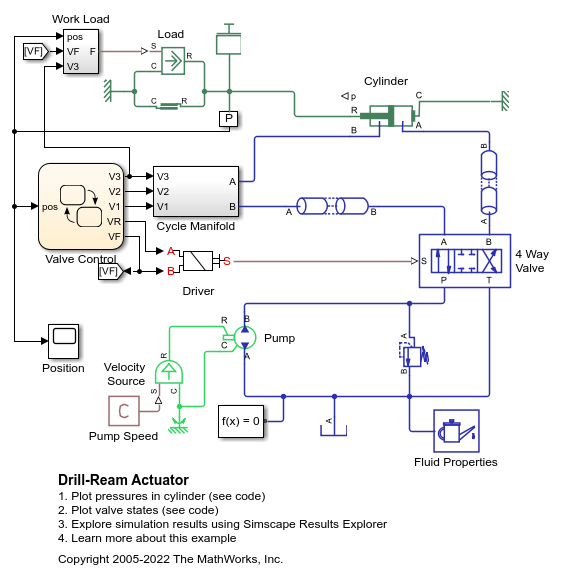
ドリルリーマ アクチュエータ
この例では、荒加工、微細穴加工、リーマ加工という 3 つの一連の技術的操作を実行する工作機械の作業ユニットを駆動するアクチュエータを示します。アクチュエータの速度は、シリンダーからの戻り流量を排出側で調整する 3 つの圧力補償流量制御バルブのいずれかで制御されます。適切な流量制御の選択は、制御ユニットで有効化される方向制御バルブによって行われます。

Pressure Reducing Valve in Punching Operation
Models a hydraulic system with a direct operated, pressure reducing valve. This system helps to limit and maintain pressure in a hydraulic punching machine. Pressure reducing valves are common in hydraulic pressing, drilling, and stamping applications.
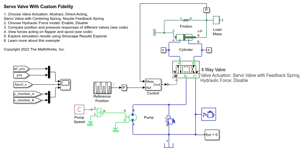
Servo Valve with Custom Fidelity
Compares the mechanical performance of various spool actuation configurations and model fidelity levels for a hydraulic 4-way 3-position directional valve. The directional valve controls a simple double-acting cylinder in a closed-loop application. This example allows you to choose among four different spool actuation designs:

ABS Open Loop Test Bench
A simple way of modeling of the anti-lock braking system (ABS) and using it with the manual braking components. The model simulates for the open loop ABS and shows the response of the pressures achieved in the caliper disc brakes. This model can be utilized in sizing of the release valve, apply valve and accumulator for the hydraulic control unit of the ABS.

アンチロック ブレーキ システム (ABS)
この例では、ABS ブレーキ システムをモデル化する簡単な方法を説明します。モデルでは、車両 CG と車輪について得られた速度プロファイル応答を示します。