Pressure Compensator Valve (IL)
Pressure compensator valve in an isothermal liquid network
Libraries:
Simscape /
Fluids /
Isothermal Liquid /
Valves & Orifices /
Pressure Control Valves
Description
The Pressure Compensator Valve (IL) block represents a pressure compensator in an isothermal liquid network, such as a pressure relief valve or pressure-reducing valve. Use this valve to maintain the pressure at the valve based on signals from another part of the system.
The pressure differential between ports X and Y is the control pressure, Pcontrol. When this value meets or exceeds the set pressure, the valve area opens or closes depending on the Valve specification parameter. The pressure regulation range begins at the set pressure, Pset. You can choose between constant and controlled set pressure regulation. A physical signal at port Ps provides a varying set pressure.
Pressure Control
The block regulates pressure when Pcontrol exceeds Pset. The block continues to regulate the pressure up to Pmax, the sum of Pset and the pressure regulation range. The block supports two modes of regulation:
When you set Set pressure control to
Controlledand connect a pressure signal to port Ps, the block keeps the pressure regulation range constant. The valve regulates pressure when Pcontrol is greater than the value of the signal at port Ps and less than Pmax.When you set Set pressure control to
Constant, the Set pressure differential parameter defines a constant set pressure.
Conservation of Mass
The block conserves mass such that
The block calculates the mass flow rate through the valve as
where:
Cd is the Discharge coefficient parameter.
Avalve is the instantaneous valve open area.
Aport is the Cross-sectional area at ports A and B parameter.
is the average fluid density.
Δp is the valve pressure difference pA – pB.
The critical pressure difference, Δpcrit, is the pressure differential specified by the Critical Reynolds number parameter, Recrit. This parameter represents the flow regime transition point between laminar and turbulent flow. The block finds the critical pressure difference as
The pressure loss, PRloss, describes the reduction of pressure in the valve due to a decrease in area. The block calculates the pressure loss as:
The pressure recovery describes the positive pressure change in the valve due to
an increase in area. When you set Pressure recovery to
Off, the block sets
PRloss to 1.
The block calculates Avalve using the opening parameterization and the valve opening dynamics.
Valve Opening Parameterization
When you set Opening parameterization to
Linear, the valve area for normally open valves is
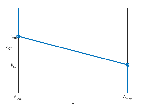
This figure demonstrates how the block controls the opening area for a normally open valve using the linear parameterization.
For normally closed valves, the block uses
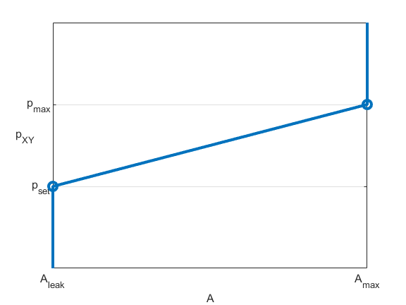
This figure demonstrates how the block controls the opening area for a normally closed valve using the linear parameterization.
The normalized pressure, , is
When the valve is in a near-open or near-closed position in the linear parameterization, you can maintain numerical robustness in your simulation by adjusting the Smoothing factor parameter. If the Smoothing factor parameter is nonzero, the block smoothly saturates the control pressure between pset and pmax. For more information, see Numerical Smoothing.
When you set Opening parameterization to
Tabulated,
Aleak and
Amax are the first and last
parameters of the Opening area vector parameter, respectively.
The block calculates the opening area as
where:
pcontrol is the control pressure, the pressure differential between ports X and Y.
pcontrol,TLU,ref = pTLU + poffset.
pTLU is the Pressure differential vector parameter.
poffset is an internal pressure offset that causes the valve to start closing when pcontrol,TLU,ref = pset.
ATLU is the Opening area vector parameter.
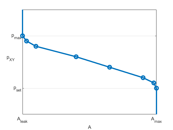
This figure demonstrates how the block controls the opening area for a normally open valve using the tabulated parameterization.
This figure demonstrates how the block controls the opening area for a normally closed valve using the tabulated parameterization.

Opening Dynamics
When you select Opening dynamics, the block applies a first-order filter to the valve area based on the Opening time constant parameter, τ. The valve area, Avalve, becomes the dynamic area, Adyn,
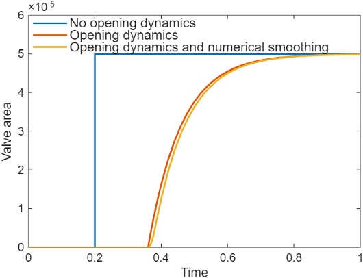
When you select Opening dynamics, the valve does not respond to changes instantaneously. This figure shows an example valve area in response to a step in the valve input pressure with and without opening dynamics:
When you clear Opening dynamics, the valve area mirrors the step change in the pressure at the input.
When you select Opening dynamics and set Opening time constant to
0.1 s, the valve area asymptotically approaches its limit.
Specifying a nonzero value for the Smoothing factor parameter provides additional numerical stability when the valve area is changing and in the near-closed or near-open position. For more information, see Numerical Smoothing.
Faults
To model a fault, in the Faults section, click the Add fault hyperlink next to the fault that you want to model. Use the fault parameters to specify the fault properties. For more information about fault modeling, see Introduction to Simscape Faults.
You can set the Opening area when faulted parameter to:
Closed— The valve area stops at its smallest value, depending on the Opening parameterization parameter setting:Linear— The valve area stops at the value of the Leakage area parameter.Tabulated— The valve area stops at the smallest element of the Opening area vector parameter.
Open— The valve stops at its largest value, depending on the Opening parameterization parameter setting:Linear— The valve area stops at the value of the Maximum opening area parameter.Tabulated— The valve area stops at the largest element of the Opening area vector parameter.
Maintain last value— The valve area stops at the valve open area when the trigger occurred.
Due to numerical smoothing at the extremes of the valve area, the minimum area the block uses is larger than the leakage area, and the maximum is smaller than the value of the Maximum orifice area parameter. This effect is in proportion to the amount of smoothing you apply.
After the fault triggers, the valve remains at the faulted area for the rest of the simulation.
Examples
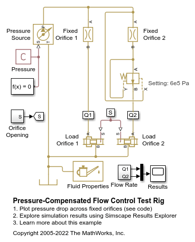
This example shows a test rig for the Pressure Compensator Valve (IL) block. A constant-pressure source connects to two flow paths that each have a fixed orifice and a variable orifice which acts as a variable load. One flow path contains a pressure compensator valve.
The Valve specification parameter of the pressure compensator valve is specified to Normally open, so the valve operates as a pressure-reducing valve. The valve prevents the pressure differential across the fixed orifice from exceeding the maximum regulation pressure, which is the sum of the values of the Set pressure differential and Pressure regulation range parameters. On the flow path with no pressure compensator valve, the flow rate varies due to the changing load.
Model
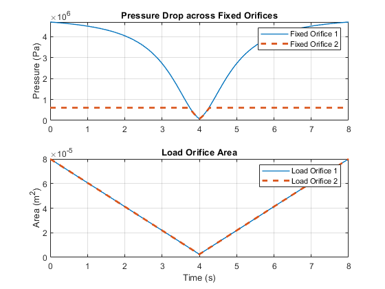
Simulation Results from Scopes
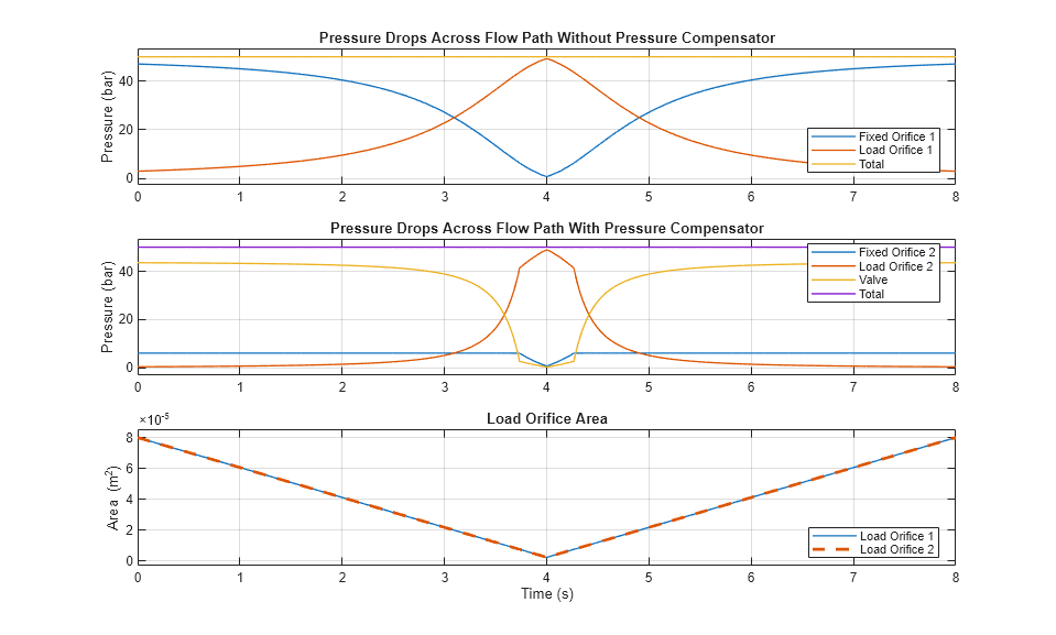
Simulation Results from Simscape Logging
These plots show the pressure drops in the system. Because of the initial large opening of the Load Orifice 1, the pressure drop across the Fixed Orifice 1 begins at a value close to the total pressure drop of 50 bar, which the pressure source specifies. The pressure drop reduces to zero when the Load Orifice 1 fully closes. In contrast, the pressure drop across the Fixed Orifice 2 is equal to or less than the maximum regulation pressure 6.075 bar, which is the sum of the set pressure differential 6 bar and the pressure regulation range 0.075 bar. The flow rate along the Fixed Orifice 2 remains nearly constant when the valve partially opens, because the pressure drop across the orifice lies in a small range between 6 bar and 6.075 bar. When the pressure drop across the Load Orifice 2 increases due to the decreasing orifice opening, the pressure drop across the Fixed Orifice 2 begins to fall below the set pressure differential 6 bar. This behavior maintains the total pressure drop of 50 bar.
Extended Examples

Drill-Ream Actuator
An actuator that drives a machine tool working unit performing a sequence of three technological operations: coarse drilling, fine drilling, and reaming. One of three pressure-compensated flow control valves controls the actuator speed as metering out return flow from the cylinder. Directional valves that are activated by a control unit perform the selection of an appropriate flow control.