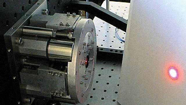
Applied Technology Associates Designs Optical Inertial Reference Unit for NASA Goddard Space Flight Center
"With MathWorks tools, we’ve eliminated throwing our algorithm designs over the wall for our software engineers to interpret. Now, with Simulink Coder and Simulink Real-Time, we can generate and run in real time the same code that we developed on the simulation side in Simulink."
Challenge
Solution
Results
- Achieved consistency of models and analysis
- Saved more than $250,000 in development costs
- Quickly compared and optimized designs

Surface and orbiting explorers on Mars send data to earth via satellite radio frequency (RF) communications. However, transmitting data over such long distances using RF communications is extremely slow. Optical laser communications have the potential to direct a communication beam more precisely, while using less power and transmitting more data faster.
Sensor manufacturer Applied Technology Associates (ATA) developed an optical inertial reference unit (IRU) for the NASA Goddard Space Flight Center that points a laser optical instrument accurately while rejecting disturbances to the line of sight. Using MathWorks tools, ATA evaluated and optimized its IRU designs, reducing development time by six months.
"MathWorks tools are a lot faster and more flexible than coding by hand," says Dan Eckelkamp-Baker, senior engineer and controls lead for optical inertial reference units at ATA. "We’ve been able to reduce errors and time-consuming testing and software debugging."
Challenge
Disturbances to an optical instrument’s line of sight often originate within the instrument. Small angular deviations from the vibrations in the instrument, when used over long distances, result in significant movement of the beam. When the instrument points a laser beam back to Earth, these deviations can significantly misdirect the beam, causing data transmission problems.
To sample and correct for deviations in the line of sight, ATA needed to create an IRU, similar to a fixed star. This reference would enable them to detect and correct the internal jitter sources, supporting increased pointing accuracy and precision.
For previous projects, ATA control engineers used a combination of development languages for various stages of the design process. This resulted in a lack of consistency among the control design models, the simulation, and the code running in real time on the hardware.
“We don’t have time to debug, test, and verify various development languages,” explains Eckelkamp-Baker. “We need to know that the algorithms we design can actually be run in real time.”
Solution
With just two engineers, ATA used MathWorks tools to model the IRU, which includes actuators, platform dynamics, and sensors. They used Simulink Coder™ and Simulink Real-Time™ to immediately test their control designs on real-time hardware.
Control engineers used Simulink® to develop system models based on first principles. Starting with idealized models, they simulated the dynamics for the motion sensors and the actuators that move the optical platform and cancel vibrations. They used MATLAB® to linearize these models for controller design.
With MATLAB and Simulink, engineers applied balancing and numerical conditioning functions and blocks to reduce the order of the dynamic model subsystems before performing control system design.
Using Signal Processing Toolbox™, they performed frequency and time domain analysis to evaluate model performance. They then used Control System Toolbox™ to explore different control techniques, and Simulink to evaluate model performance parameters.
Next, engineers used DSP System Toolbox™ to build signals into the model. They used the model profiler in Simulink to identify performance bottlenecks. Simulink Design Optimization™ and Optimization Toolbox™ enabled them to refine their filters and controllers to obtain optimal performance.
Finally, ATA used Simulink Coder to automatically generate C code from the Simulink model. They ran the code in real time for each test using Simulink Real-Time, which runs on a desktop PC that includes three General Standards PCI-ADADIO boards. Sixteen analog input channels were dedicated to motion sensor inputs, four for actuator current measurements, and four for laser-scoring sensors on the test system. ATA engineers used four analog outputs to drive the actuators, and 24 digital outputs to set PGA gains for their custom electronics.
“Using Simulink Real-Time is so easy,” Eckelkamp-Baker explains. “You just set up the parameters, create the code, and run it on a desktop PC.”
ATA is in the final stages of testing its first-generation IRU for NASA Goddard.
Results
Achieved consistency of models and analysis. “The scripts that we run against the simulation model for data analysis are the same as those we run against real data from Simulink Real-Time,” Eckelkamp-Baker says. “It was incredible how accurate our models and performance predictions turned out to be.”
Saved more than $250,000 in development costs. “If we hadn’t used Simulink Coder and Simulink Real-Time, it would have added another six months to a year to our project schedule,” explains Eckelkamp-Baker. “We saved more than $250,000 using MathWorks tools.”
Quickly compared and optimized designs. “We use filter and controller design methods and compare their performance,” says Eckelkamp-Baker. “Using Simulink and Simulink Real-Time, we changed from classical designs to state-space designs and ran new real-time tests within minutes.”