Reconstruct 3-D Scene from Geometrically Refined Pair of Initial Views
This example shows how to initialize a reconstruction from the view graph refined in the Refine View Graph Using Geometric Verification example by estimating the relative pose between the two views, triangulating 3-D points and then validating the pair based using multi-view geometry criteria commonly used in Structure from Motion (SfM).
The reconstruction begins with a carefully chosen two-view initialization [1]. The quality of this pair strongly affects robustness, accuracy, and runtime of the subsequent stages. Errors introduced at this step can propagate and become difficult to correct later. A strong initial pair typically comes from a densely connected region of a refined view graph, where both images share substantial overlap in the scene. This redundancy stabilizes relative pose estimation and triangulation. A good initial pair generally:
Has a large number of geometrically verified feature matches that are uniform over the spatial extent of the image.
Exhibits a sufficiently wide baseline (i.e., larger triangulation angles) to enable stable depth estimation.
Produces many triangulated 3-D points with low reprojection error.
Load Data
First, ensure that the images are available on the path.
% Check if the image datastore exists. If not, load images.
if ~exist("imds", "var")
    downloadFolder = tempdir;
    imageFolder = fullfile(downloadFolder, "sfmTrainingDataTUMRGBD", "images");
    imds = imageDatastore(imageFolder);
end
Load the view graph refined from the Refine View Graph Using Geometric Verification example.
% Check if a view graph exists in workspace. If not, load it from MAT file.
if ~exist("viewGraph", "var")
    viewGraphFile = fullfile(downloadFolder, "sfmTrainingDataTUMRGBD", "refinedViewGraph.mat");
    viewGraphData = load(viewGraphFile);
    viewGraph = viewGraphData.viewGraph;
end
Load camera intrinsic parameters, which will be used later in estimation of the essential matrix.
% Load camera intrinsics
intrinsicsFile = fullfile(downloadFolder, "sfmTrainingDataTUMRGBD", "cameraInfo.mat");
data = load(intrinsicsFile);
intrinsics = data.intrinsics;
Select Strongly-connected View Pairs in View Graph
Select edges in the view graph that have a large number of geometrically verified matches. A common threshold is 100–200 matches, depending on image resolution. For 480-by-640 images in this example, we use 100. More inliers generally make the relative pose estimate more robust.
minNumMatchesInitial = 100;
isStrongEdge = cellfun(@(x)(size(x,1)>minNumMatchesInitial), viewGraph.Connections.Matches);

numSelectedConn = nnz(isStrongEdge);
selectedConnIdx = find(isStrongEdge); % convert to linear indices

disp(numSelectedConn + " of " + viewGraph.NumConnections +...
" edges have more than " + minNumMatchesInitial + " feature matches.");
349 of 429 edges have more than 100 feature matches.
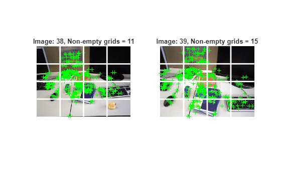
Select View Pairs with Uniformly Distributed Matched Feature Points
Select image pairs whose inlier features are uniformly spread across images. This prevents degenerate conditions that can cause triangulation to fail.
numImages = numel(imds.Files); % Display the selected connection idx =151; connId = selectedConnIdx(idx); matchedPairs = viewGraph.Connections.Matches{connId}; % View indexes for the two views being considered viewIds1 = viewGraph.Connections.ViewId1; viewIds2 = viewGraph.Connections.ViewId2; viewId1 = viewIds1(connId); viewId2 = viewIds2(connId); view1 = findView(viewGraph, viewId1); view2 = findView(viewGraph, viewId2); points1 = view1.Points{:}; points2 = view2.Points{:}; % Get the matched SIFT points matchedPoints1 = points1(matchedPairs(:,1)); matchedPoints2 = points2(matchedPairs(:,2)); % Read image pair I1 = readimage(imds, viewId1); I2 = readimage(imds, viewId2); % Create a 4-by-4 grid on the image and plot each line numCols = 4; numRows = 4; [H, W] = size(I1, [1 2]); [rowIdx, colIdx, lines] = helperImageGridIndices(H, W, numRows,numCols); % Count the number of grids that contain at least one feature point gridCounts1 = helperCountKeypointsPerGrid(rowIdx, colIdx, matchedPoints1); gridCounts2 = helperCountKeypointsPerGrid(rowIdx, colIdx, matchedPoints2); % Display the selected images figure subplot(1,2,1) imshow(I1); hold on % Plot the feature point locations plot(matchedPoints1, ShowScale=false); xCoords = [lines(:,1), lines(:,3)]' - 0.5; yCoords = [lines(:,2), lines(:,4)]' - 0.5; plot(xCoords, yCoords, "w-", LineWidth=2); title("Image: " + viewId1 + ", Non-empty grids = " + nnz(gridCounts1)); subplot(1,2,2) imshow(I2); % Plot the feature point locations hold on plot(matchedPoints2, ShowScale=false); xCoords = [lines(:,1), lines(:,3)]' - 0.5; yCoords = [lines(:,2), lines(:,4)]' - 0.5; plot(xCoords, yCoords, "w-", LineWidth=2); title("Image: " + viewId2 + ", Non-empty grids = " + nnz(gridCounts2));
Apply this coverage test to every selected edge. If fewer than 50% of the grid cells are non-empty, exclude that edge from initialization.
uniformConnIdx = [];
minGridCount = 8; % 8 out of 16 grid cells should have at least 1 inlier keypoint
for idx = 1:numSelectedConn
    connId = selectedConnIdx(idx);
    matchedPairs = viewGraph.Connections.Matches{connId};

    % View indexes for the two views being considered
    viewId1 = viewIds1(connId);
    viewId2 = viewIds2(connId);
    view1   = findView(viewGraph, viewId1);
    view2   = findView(viewGraph, viewId2);
    points1 = view1.Points{:};
    points2 = view2.Points{:};

    % Get the matched SIFT points
    matchedPoints1 = points1(matchedPairs(:,1));
    matchedPoints2 = points2(matchedPairs(:,2));

    % Read image pair
    I1 = readimage(imds, viewId1);
    I2 = readimage(imds, viewId2);

    gridCounts1 = helperCountKeypointsPerGrid(rowIdx, colIdx, matchedPoints1);
    gridCounts2 = helperCountKeypointsPerGrid(rowIdx, colIdx, matchedPoints2);

    if nnz(gridCounts1) > minGridCount && nnz(gridCounts2) > minGridCount
        uniformConnIdx = [uniformConnIdx; connId]; %#ok<*AGROW>
    end
end
numUniformConns = numel(uniformConnIdx);
disp(numUniformConns + " of " + numSelectedConn + " are selected after applying the grid threshold.")
324 of 349 are selected after applying the grid threshold.
Initialize Two-View Reconstruction for an Image Pair
After identifying inlier feature matches between two views, evaluate the geometric relationship using two transformation models: homography and essential matrix. The transform that results in a smaller reprojection error is selected to estimate the relative rotation and translation using estrelpose. Because the images are captured with a monocular camera, depth information is not directly available, and the estimated translation is only recoverable up to scale. Additionally, filter out configurations with near-pure forward motion, as they tend to produce low parallax which lead to inaccurate depth estimation and unreliable triangulation.
% Select an edge connecting two views from the remaining set of edges idx =90; connId = uniformConnIdx(idx); viewId1 = viewIds1(connId); viewId2 = viewIds2(connId); matchedPairs = viewGraph.Connections.Matches{connId}; % Get the keypoints for that view view1 = findView(viewGraph, viewId1); view2 = findView(viewGraph, viewId2); points1 = view1.Points{:}; points2 = view2.Points{:}; % Get the matched SIFT points matchedPoints1 = points1(matchedPairs(:,1)); matchedPoints2 = points2(matchedPairs(:,2)); % Suppress innocuous warnings related to RANSAC warning("off","vision:ransac:maxTrialsReached"); warning("off","images:geotrans:transformationMatrixBadlyConditioned"); % Compute homography and evaluate reconstruction [tformH, scoreH, inliersIndexH] = helperComputeHomography(matchedPoints1, matchedPoints2); % Compute essential matrix and evaluate reconstruction [tformE, scoreE, inliersIndexE] = helperComputeEssentialMatrix(matchedPoints1, matchedPoints2, intrinsics, intrinsics); % Select the transform based on a heuristic ratio = scoreH/(scoreH + scoreE); ratioThreshold = 0.45; if ratio > ratioThreshold inlierTformIdx = inliersIndexH; tform = tformH; else inlierTformIdx = inliersIndexE; tform = tformE; end % Compute relative pose between the two views inlierPoints1 = matchedPoints1(inlierTformIdx); inlierPoints2 = matchedPoints2(inlierTformIdx); matchedPairs = matchedPairs(inlierTformIdx, :); [relPose, validFraction] = estrelpose(tform, intrinsics, intrinsics, inlierPoints1, inlierPoints2); % Compute forward motion ratio which quantifies how much the camera moved % along its optical axis (viewing direction) relative to the baseline between % two camera positions. forwardMotionRatio = abs(dot(relPose.Translation, [0 0 1])); % Discard if not enough inliers are found or forward motion ratio is high minValidFraction = 0.5; maxFowardMotionRatio = 0.95; isPoseValid = validFraction > minValidFraction && isscalar(relPose) &&... forwardMotionRatio < maxFowardMotionRatio; if ~isPoseValid disp("The connection between view " + viewId1 + " and " + viewId2 + " is invalid. Select a different connection."); return end
Given the relative camera pose and the matched feature points in the two images, determine the 3-D locations of the matched points using triangulate function. A triangulated 3-D point is considered valid if it meets these geometric criteria:
It lies in front of both cameras, indicating positive depth values.
It has a low reprojection error, ensuring consistency between the observed and projected image points.
The triangulation angle—the angle between the viewing rays from the two cameras—is sufficiently large, which improves depth accuracy and stability.
To ensure robustness against matching outliers, the median triangulation angle across all triangulated points should also be large. This helps maintain reliable depth estimation and prevents degenerate configurations caused by matching outliers.
% Thresholds for selecting the initial pair of views
% minMedianTriAngle - Minimum acceptable median triangulation angle across 3-D points from the two views
% minTriAnglePoint  - Minimum triangulation angle required for a 3-D point to be considered valid
% maxReprojError    - Maximum allowable reprojection error for a triangulated 3-D point to be valid
minMedianTriAngle = 16;  % in degrees
minTriAnglePoint  = 1.5; % in degrees
maxReprojError    = 4;   % in pixels

% Triangulate the two views to obtain 3-D world points
pose1 = rigidtform3d();
pose2 = relPose;

% Get camera projection matrix
camMatrix1 = cameraProjection(intrinsics, pose2extr(pose1));
camMatrix2 = cameraProjection(intrinsics, pose2extr(pose2));

% Triangulate two views to obtain 3-D map points
[xyzPoints, reprojectionErrors, isInFront] = triangulate(inlierPoints1, inlierPoints2, camMatrix1, camMatrix2);

% Compute triangulation angles in degrees for each triangulate 3-D point
ray1       = xyzPoints - pose1.Translation;
ray2       = xyzPoints - pose2.Translation;
triAngles  = acosd(sum(ray1 .* ray2, 2) ./ (vecnorm(ray1, 2, 2) .* vecnorm(ray2, 2, 2)));

% Filter points by view direction and reprojection error
inlierTriangulationIdx  = isInFront & reprojectionErrors < maxReprojError & triAngles > minTriAnglePoint;
xyzPoints  = xyzPoints(inlierTriangulationIdx ,:);
matchedPairs = matchedPairs(inlierTriangulationIdx, :);

% Check parallax in terms of median triangulation angle
medianAngle = median(triAngles);
isValid = medianAngle > minMedianTriAngle;
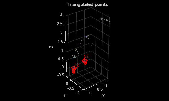
Visualize the images and the triangulated 3-D points.
% Load the image for the specified view ID
I1 = readimage(imds, viewId1);
I2 = readimage(imds, viewId2);

figure
imshowpair(I1, I2, "montage");
title("Images: " + viewId1 + " and " + viewId2);
truesize
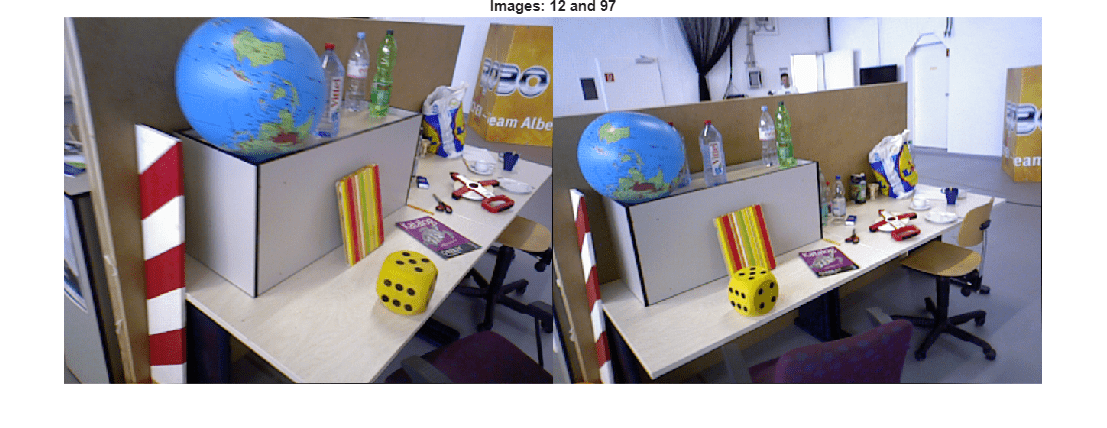
figure
% Get color of 3-D points from the two images
colors = helperGetPointColorsFromTwoViews(I1, I2, viewId1, viewId2, viewGraph, matchedPairs);

% Plot 3-D points
pcshow(xyzPoints, colors, MarkerSize=30);
xlabel("X")
ylabel("Y")
zlabel("Z")
hold on

% Plot cameras
plotCamera([pose1, pose2], Label={num2str(viewId1), num2str(viewId2)}, Size=0.1);
title("Triangulated points");
Apply the two-view reconstruction procedure to all image pairs in the refined view graph using the helper function helperReconstructTwoView, which encapsulates the validation steps described in the previous section. For each pair, estimate the relative pose, triangulate 3-D points, and validate the reconstruction based on geometric criteria. After processing all pairs, select the pair that yields the highest number of valid triangulated 3-D points. If no pair meets the required criteria gradually relax the median triangulation angle threshold to allow for a viable initialization while maintaining geometric robustness.
% Select initial view pair
initConnId        = [];
initTriAngle      = [];
initXYZPoints     = [];
initRelPose       = [];
initMatches       = [];
initInlierIndices = [];

rng(0); % For reproducibility

for idx = 1:numUniformConns
    connId  = uniformConnIdx(idx);
    viewId1 = viewIds1(connId);
    viewId2 = viewIds2(connId);
    matchedPairs = viewGraph.Connections.Matches{connId};

    % Get the keypoints for that view
    view1   = findView(viewGraph, viewId1);
    view2   = findView(viewGraph, viewId2);
    points1 = view1.Points{:};
    points2 = view2.Points{:};

    [isValid, xyzWorldPoints, inlierMatchIndices, medianTriAngle, relPose] = ...
        helperReconstructTwoView(points1, points2, matchedPairs, intrinsics,...
        MaxReprojectionError        = maxReprojError, ...
        MinTriangulationAnglePoint  = minTriAnglePoint, ...
        MinMedianTriangulationAngle = minMedianTriAngle, ...
        MinValidFraction            = minValidFraction, ...
        MaxFowardMotionRatio        = maxFowardMotionRatio);

    if isValid
        % Pick the pair with most high-quality triangulated points.
        if nnz(inlierMatchIndices) > nnz(initInlierIndices)
            initConnId        = connId;
            initTriAngle      = medianTriAngle;
            initXYZPoints     = xyzWorldPoints;
            initRelPose       = relPose;
            initMatches       = matchedPairs;
            initInlierIndices = inlierMatchIndices;
        end
    end
end

if isempty(initConnId)
    disp("No pair can be found. Reduce the value of minMedianTriAngle.");
end

% Restore warnings after the loop
warning("on","vision:ransac:maxTrialsReached");
warning("on","images:geotrans:transformationMatrixBadlyConditioned");
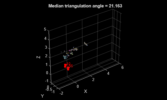
Visualize the initial image pair and sparse reconstruction.
viewId1 = viewIds1(initConnId);
viewId2 = viewIds2(initConnId);

% Load the image for the specified view ID
I1 = readimage(imds, viewId1);
I2 = readimage(imds, viewId2);

figure
imshowpair(I1, I2, "montage");
title("Images: " + viewId1 + " and " + viewId2);
truesize
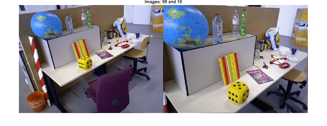
figure
% Get color of 3-D points from the two images
matchedPairs = initMatches(initInlierIndices, :);
colors = helperGetPointColorsFromTwoViews(I1, I2, viewId1, viewId2, viewGraph, matchedPairs);

% Plot 3-D points
pcshow(initXYZPoints, colors, MarkerSize=30);
xlabel("X")
ylabel("Y")
zlabel("Z")
hold on

% Plot cameras
plotCamera([pose1, initRelPose], Label=string([viewId1, viewId2]), Size=0.1);
xlim([-2, 6]);
zlim([-1, 5]);
title("Median triangulation angle = " + initTriAngle);
Refine Initial Reconstruction Using Bundle Adjustment
After triangulating from the initial pair, update the view graph with the estimated relative pose and add the 3-D points and their image correspondences to a worldpointset object. Then refine the initial reconstruction using bundleAdjustment, which optimizes both camera poses and world points to minimize the overall reprojection errors.
% Update the pose of the second view. The pose of the first view is assumed
% identify transform.
viewGraph = updateView(viewGraph, viewId2, initRelPose);

% Update relative pose between the initial two view and feature matching
viewGraph = updateConnection(viewGraph, viewId1, viewId2, initRelPose, Matches=matchedPairs);

% Add 3-D points
wpSet = worldpointset();
[wpSet, pointIndices] = addWorldPoints(wpSet, initXYZPoints);

% Add 3-D to 2-D correspondences
wpSet = addCorrespondences(wpSet, viewId1, pointIndices, matchedPairs(:,1));
wpSet = addCorrespondences(wpSet, viewId2, pointIndices, matchedPairs(:,2));

% Perform bundle adjustment to refine the poses of first two views and the triangulated
% 3-D point locations
[wpSet, viewGraph, mapPointIdx, reprojectionErrors] = bundleAdjustment(...
    wpSet, viewGraph, [viewId1, viewId2], intrinsics, FixedViewIDs=viewId1, ...
    PointsUndistorted=true, AbsoluteTolerance=1e-7,...
    RelativeTolerance=1e-16, Solver="preconditioned-conjugate-gradient");
After bundle adjustment, remove 3-D points with large reprojection errors or insufficient triangulation angle.
% Get refined poses of the two views
camPosesTable = poses(viewGraph, [viewId1, viewId2]);

% Compute triangulation angle in degrees of each refined 3-D point
xyzPoints = wpSet.WorldPoints(mapPointIdx,:);
ray1      = xyzPoints - camPosesTable.AbsolutePose(1).Translation;
ray2      = xyzPoints - camPosesTable.AbsolutePose(2).Translation;
triAngles = acosd(sum(ray1 .* ray2, 2) ./ (vecnorm(ray1, 2, 2) .* vecnorm(ray2, 2, 2)));

% Remove 3-D points with large reprojection error or smaller triangulation angle
isOutlier = reprojectionErrors > maxReprojError | triAngles < minTriAnglePoint;
wpSet = removeWorldPoints(wpSet, mapPointIdx(isOutlier));
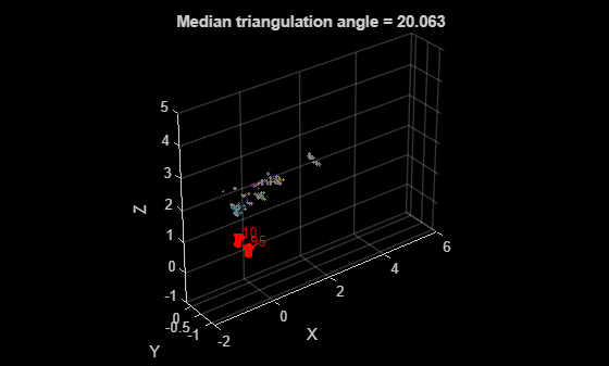
Display the reconstruction after bundle adjustment.
figure
% Plot 3-D points
pcshow(wpSet.WorldPoints, colors(~isOutlier, :), MarkerSize=30);
xlabel("X")
ylabel("Y")
zlabel("Z")
hold on

% Plot cameras
plotCamera(camPosesTable, Size=0.1);
xlim([-2, 6]);
zlim([-1, 5]);
title("Median triangulation angle = " + median(triAngles(~isOutlier)));
After the initial construction, process the remaining views in the view graph to expand the reconstructed 3-D scene. See the Reconstruct Complete 3-D Scene Using Incremental Structure from Motion example for the next steps.
Supporting Files
helperImageGridIndices divide an image into grids.
function [rowIdx,colIdx,lines] = helperImageGridIndices(H,W,numRows,numCols)

% Compute row edges
rowEdges = round(linspace(1, H+1, numRows+1));
% Compute col edges
colEdges = round(linspace(1, W+1, numCols+1));

% Assemble start and end indices for rows
rowIdx = [rowEdges(1:end-1)', rowEdges(2:end)'-1];

% Assemble start and end indices for columns
colIdx = [colEdges(1:end-1)', colEdges(2:end)'-1];

% Reconstruct edges for drawing grid lines
rowEdgesForLines = rowIdx(:,1);
colEdgesForLines = colIdx(:,1);
rowLinesY = rowEdgesForLines(2:end);
colLinesX = colEdgesForLines(2:end);

% Grid lines: [[x1 y1 x2 y2]; ....]
lines = [];
for y = rowLinesY'
    lines = [lines; 1 y W y];
end

for x = colLinesX'
    lines = [lines; x 1 x H];
end
end
helperCountKeypointsPerGrid count the number of keypoint located in each grid.
function gridCounts = helperCountKeypointsPerGrid(rowIdx, colIdx, points)

% Generate row and col edges from rowIdx and colIdx
% These edges cover the full extent
rowEdges = [rowIdx(:,1); rowIdx(end,2)+1];
colEdges = [colIdx(:,1); colIdx(end,2)+1];

% Extract x and y
x = points.Location(:,1);
y = points.Location(:,2);

% Bin the y coordinates to row bins
[rowBin,~] = discretize(y, rowEdges);

% Bin the x coordinates to column bins
[colBin,~] = discretize(x, colEdges);

% Remove rows with NaN bin indices
valid = ~isnan(rowBin) & ~isnan(colBin);

% Create subscripts
subs = [rowBin(valid), colBin(valid)];

% Count occurrences within each grid bin
gridCounts = accumarray(subs, 1, [size(rowIdx,1), size(colIdx,1)]);
end
helperComputeEssentialMatrix compute essential matrix and evaluate reconstruction.
function [E, score, inliersIndex] = helperComputeEssentialMatrix(matchedPoints1, matchedPoints2, intrinsics1, intrinsics2)

outlierThreshold = 4;

[E, inliersIndex, status] = estimateEssentialMatrix( ...
    matchedPoints1, matchedPoints2, intrinsics1, intrinsics2, MaxNumTrials=1e3, MaxDistance=outlierThreshold);

if status % No valid essential matrix can be found
    score = outlierThreshold*size(matchedPoints1,1);
    return
end

F = intrinsics1.K'\ E /intrinsics2.K;

inlierPoints1 = matchedPoints1(inliersIndex);
inlierPoints2 = matchedPoints2(inliersIndex);

locations1    = inlierPoints1.Location;
locations2    = inlierPoints2.Location;

% Distance from points to epipolar line
lineIn1   = epipolarLine(F', locations2);
error2in1 = (sum([locations1, ones(size(locations1, 1),1)].* lineIn1, 2)).^2 ...
    ./ sum(lineIn1(:,1:2).^2, 2);
lineIn2   = epipolarLine(F, locations1);
error1in2 = (sum([locations2, ones(size(locations2, 1),1)].* lineIn2, 2)).^2 ...
    ./ sum(lineIn2(:,1:2).^2, 2);

score = sum(max(outlierThreshold-error1in2, 0)) + ...
    sum(max(outlierThreshold-error2in1, 0));
end
helperComputeHomography compute homography and evaluate reconstruction.
function [H, score, inliersIndex] = helperComputeHomography(matchedPoints1, matchedPoints2)

outlierThreshold = 6;

[H, inliersIndex] = estgeotform2d( ...
    matchedPoints1, matchedPoints2, "projective", ...
    MaxNumTrials=1e3, MaxDistance=outlierThreshold);

inlierPoints1 = matchedPoints1(inliersIndex);
inlierPoints2 = matchedPoints2(inliersIndex);

locations1 = inlierPoints1.Location;
locations2 = inlierPoints2.Location;
xy1In2     = transformPointsForward(H, locations1);
xy2In1     = transformPointsInverse(H, locations2);
error1in2  = sum((locations2 - xy1In2).^2, 2);
error2in1  = sum((locations1 - xy2In1).^2, 2);

score = sum(max(outlierThreshold-error1in2, 0)) + ...
    sum(max(outlierThreshold-error2in1, 0));
end
helperReconstructTwoView perform 3-D reconstruction from two-views.
function [isValid, xyzPoints, inlierMatchIndices, medianTriAngle, relPose] = ...
    helperReconstructTwoView(points1,points2,matchedPairs,intrinsics,args)
arguments
    points1
    points2
    matchedPairs
    intrinsics
    args.MaxReprojectionError = 4
    args.MinTriangulationAnglePoint  = 1.5
    args.MinMedianTriangulationAngle = 16
    args.MinValidFraction            = 0.5
    args.MaxFowardMotionRatio        = 0.95
end

% Get the matched SIFT points
matchedPoints1 = points1(matchedPairs(:,1));
matchedPoints2 = points2(matchedPairs(:,2));

% Suppress innocuous warnings related to RANSAC
warning("off","vision:ransac:maxTrialsReached");
warning("off","images:geotrans:transformationMatrixBadlyConditioned");

% Compute homography and evaluate reconstruction
[tformH, scoreH, inliersIndexH] = helperComputeHomography(matchedPoints1, matchedPoints2);

% Compute essential matrix and evaluate reconstruction
[tformE, scoreE, inliersIndexE] = helperComputeEssentialMatrix(matchedPoints1, matchedPoints2, intrinsics, intrinsics);

% Select the model based on a heuristic
ratio = scoreH/(scoreH + scoreE);
ratioThreshold = 0.45;
if ratio > ratioThreshold
    inlierTformIdx = inliersIndexH;
    tform       = tformH;
else
    inlierTformIdx = inliersIndexE;
    tform       = tformE;
end

% Compute relative pose between the two views
inlierPoints1 = matchedPoints1(inlierTformIdx);
inlierPoints2 = matchedPoints2(inlierTformIdx);
[relPose, validFraction] = estrelpose(tform, intrinsics, intrinsics, inlierPoints1, inlierPoints2);

xyzPoints=[];
inlierMatchIndices=[];
medianTriAngle=[];

if ~isscalar(relPose)
    isValid = false;
    return
end

% Compute forward motion ratio which quantifies how much the camera moved
% along its optical axis (viewing direction) relative to the baseline between
% two camera positions.
forwardMotionRatio = abs(dot(relPose.Translation, [0 0 1]));

% Discard if not enough inliers are found or forward motion ratio is high
isPoseValid = validFraction > args.MinValidFraction && isscalar(relPose) &&...
    forwardMotionRatio < args.MaxFowardMotionRatio;

if ~isPoseValid
    isValid = false;
    return
end

% Triangulate the two views to obtain 3-D world points
pose1 = rigidtform3d();
pose2 = relPose;

% Get camera projection matrix
camMatrix1 = cameraProjection(intrinsics, pose2extr(pose1));
camMatrix2 = cameraProjection(intrinsics, pose2extr(pose2));

% Triangulate two views to obtain 3-D map points
[xyzPoints, reprojectionErrors, isInFront] = triangulate(inlierPoints1, inlierPoints2, camMatrix1, camMatrix2);

% Compute triangulation angles in degrees for each triangulate 3-D point
ray1       = xyzPoints - pose1.Translation;
ray2       = xyzPoints - pose2.Translation;
cosAngle   = acosd(sum(ray1 .* ray2, 2) ./ (vecnorm(ray1, 2, 2) .* vecnorm(ray2, 2, 2)));

% Filter points by view direction and reprojection error
inlierTriangulationIdx  = isInFront & reprojectionErrors < args.MaxReprojectionError & cosAngle > args.MinTriangulationAnglePoint;
xyzPoints  = xyzPoints(inlierTriangulationIdx ,:);

% Check parallax in terms of median triangulation angle
medianTriAngle = median(cosAngle);
isValid = medianTriAngle > args.MinMedianTriangulationAngle;

inlierTformIdxLinearIdx = find(inlierTformIdx);
inlierMatchIndices = inlierTformIdxLinearIdx(inlierTriangulationIdx);
end
helperGetPointColorsFromTwoViews compute color of 3-D points as the average of two images.
function colors = helperGetPointColorsFromTwoViews(I1, I2, viewId1, viewId2, viewGraph, matchedPairs)
colors = zeros(size(matchedPairs, 1), 3, "uint8");
points1 = findView(viewGraph, viewId1).Points{:};
points2 = findView(viewGraph, viewId2).Points{:};
xy1 = round(points1.Location(matchedPairs(:, 1), :));
xy2 = round(points2.Location(matchedPairs(:, 2), :));
for i = 1:size(colors, 1)
    colors(i, :) = (I1(xy1(i, 2), xy1(i, 1), :) + I2(xy2(i, 2), xy2(i, 1), :))/2 ;
end
end
References
[1] Schonberger, Johannes L., and Jan-Michael Frahm. "Structure-from-motion revisited." In Proceedings of the IEEE conference on computer vision and pattern recognition, pp. 4104-4113. 2016.
See Also
estrelpose | triangulate | worldpointset | bundleAdjustment