Customize Unreal Engine Scenes Using Simulink and Unreal Editor
After you install the UAV Toolbox Interface for Unreal Engine® Projects as described in Install Support Package for Customizing Scenes, you can simulate UAV scenarios in custom scenes using the Unreal® Editor and Simulink® cosimulation framework. This topic shows you how to establish a connection between your Simulink model and Unreal Editor, create or modify scenes, and run the simulation.
Open Unreal Editor from Simulink
To establish a connection between your Simulink model and Unreal Editor, you must open
the Unreal Editor from a Simulink model that contains a Simulation 3D Scene
Configuration block, or from MATLAB® by using the open
function. For an example of a Simulink model that contains a Simulation 3D Scene
Configuration block, see the Visualize VTOL UAV Takeoff and Forward Transition example.
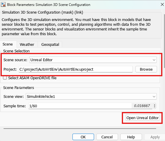
In the Simulink model, open the Simulation 3D Scene Configuration block and specify these parameters:
Scene source —
Unreal Editor.Project — Path of the Unreal project file that contains the scene you want to customize. For example, this sample path specifies the
AutoVrtlEnvproject that comes installed with the UAV Toolbox Interface for Unreal Engine Projects:C:\project\AutoVrtlEnv\AutoVrtlEnv.uproject.
To open Unreal editor, Click Open Unreal Editor.
Note
Verify that the MathWorks Interface and MathWorks UAV Content plugins are installed. From the Unreal Editor menu, select Plugins. Enable the plugins by selecting the Enabled box for both plugins, then restart Unreal Editor if prompted. For more details on installing these plugins, see Install Support Package for Customizing Scenes.
If you use a custom Unreal project file, you must reparent the level script actor class, and set the default game mode. For more details, see Reparent Level Script Actor Class and Set Default Game Mode, respectively.
Create or Modify Scenes in Unreal Editor
After you open Unreal Editor from Simulink, you can modify the scenes in your project or create new scenes.
Open Scene
To open a prebuilt scene from the UAV Toolbox Interface for Unreal Engine Projects, first select Content Drawer, then Settings, and select the Show Engine Content and Show Plugin Content options.
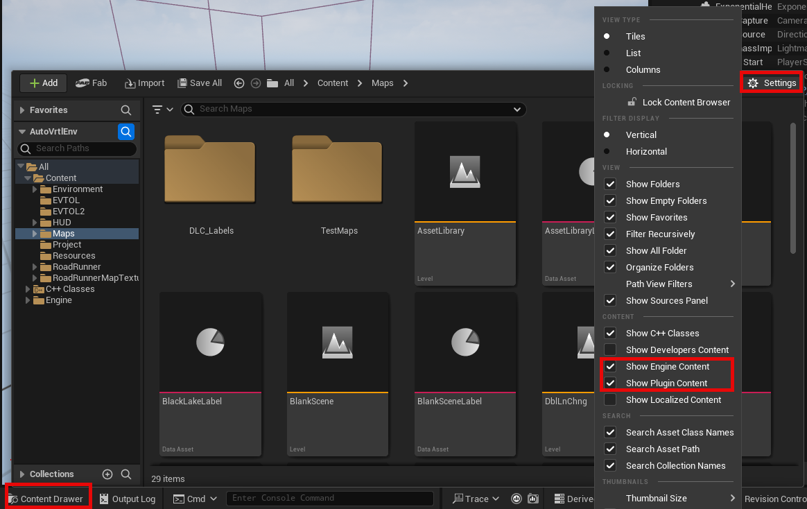
Browse the Content Drawer, then double-click the scene that you want to open.
| Scene | Unreal Editor Map | Location in Content Browser |
|---|---|---|
| US City Block | USCityBlock | All\Content\Maps |
| Suburban scene | Suburban | All\Engine\Plugins\MathWorks UAV Content
Content\Maps |
To open a scene within your own project, in the Content Drawer, navigate to the folder that contains your scenes.
Note
Unreal Editor shows a message that contains '_BuiltData'
the first time you open a scene, or when you add new elements to a scene. This
message indicates missing lighting data for the scene. To resolve this, rebuild
the lighting in Unreal Editor by selecting Build, then Build Lighting
Only.
Create New Scene
To create a new scene in your project, select File, then click New level. You can
also create a new scene by modifying one of the prebuilt scenes in the
AutoVrtlEnv project. To save the modified scene as a new
scene, select File, then click Save Current As.
Note
If you create a new custom scene, you must reparent the level blueprint before running the simulation. For more details on this step, see Reparent Level Blueprint.
Add Assets to Scene
The AutoVrtlEnv project contains a library of assets that are
built as static meshes and begin with the prefix SM_. Search for
these objects in the Content Drawer.
For example, to add a stop sign to a scene in the AutoVrtlEnv project:
In the Content Drawer at the bottom of the editor, navigate to the
Contentfolder.In the search bar, search for
SM_StopSign. Drag the stop sign from the Content Drawer to the editing window.To change the position of the stop sign, drag the stop sign in the editing window or specify a new location in the Transform section of the Details pane. The Unreal Editor uses a left-handed Cartesian world coordinate system in which the positive Y-axis points right with respect to the positive X-axis, and the positive Z-axis points upward.
For more information on modifying scenes, adding assets, and migrating assets between projects in Unreal Editor, see the Unreal Engine 5.4 Documentation.
To enable semantic segmentation, you must add stencil IDs to new objects you added to the scene. For an example of how to add stencil IDs, see the Apply Semantic Segmentation Labels to Custom Scenes example.
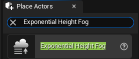
Override Default Weather
To override the default weather or use enhanced fog conditions in the scene, add the Exponential Height Fog actor by using the Place Actors menu.
Use AutoVrtlEnv Project Lighting in Custom Scene
To use the lighting included by UAV Toolbox in the AutoVrtlEnv
project, first open the World Settings tab, and, in
the Lightmaps section, clear
Force No Precomputed Lighting.
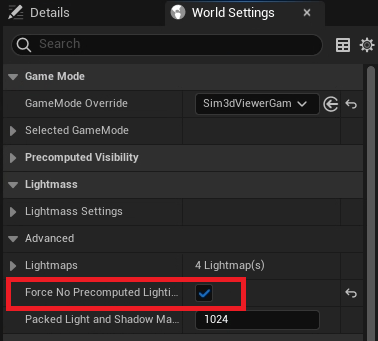
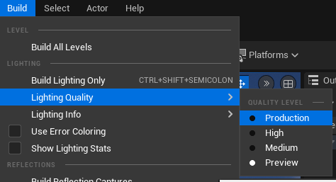
Then, rebuild the maps with production-quality lighting by selecting Build, then Lighting Quality, and then Production.
Reparent Level Blueprint
Note
You must complete this section if you create a new scene. If you are using a scene
from the AutoVrtlEnv project that comes installed with the UAV
Toolbox Interface for Unreal Engine Projects, skip this section.
The level blueprint controls how objects interact with the Unreal Engine environment.
The first time that you open a custom scene, you must reparent the scene with the
Sim3dLevelScriptActor level blueprint. You must reparent each
scene in a custom project separately.
To reparent the level blueprint:
From the Unreal Editor toolbar, select Blueprints, then click Open Level Blueprint.
In the Level Blueprint window, select File, then click Reparent Blueprint.
Select the
Sim3dLevelScriptActorblueprint.Note
If you do not see the
Sim3dLevelScriptActorblueprint listed, verify that the MathWorks Interface plugin is installed by clicking Edit, then clicking Plugins. Enable the plugin by selecting the Enabled box next to it, then restart Unreal Editor. For more details on installing this plugin, see Install Support Package for Customizing Scenes.Close the Level Blueprint window.
Reparent Level Script Actor Class
Note
You must complete this section if you use a custom project. If you are using the
AutoVrtlEnv project that comes installed with the UAV Toolbox
Interface for Unreal Engine Projects, skip this section.
If you use a custom project, you must reparent the level script actor class by using these steps:
Select Edit, then click Project Settings.
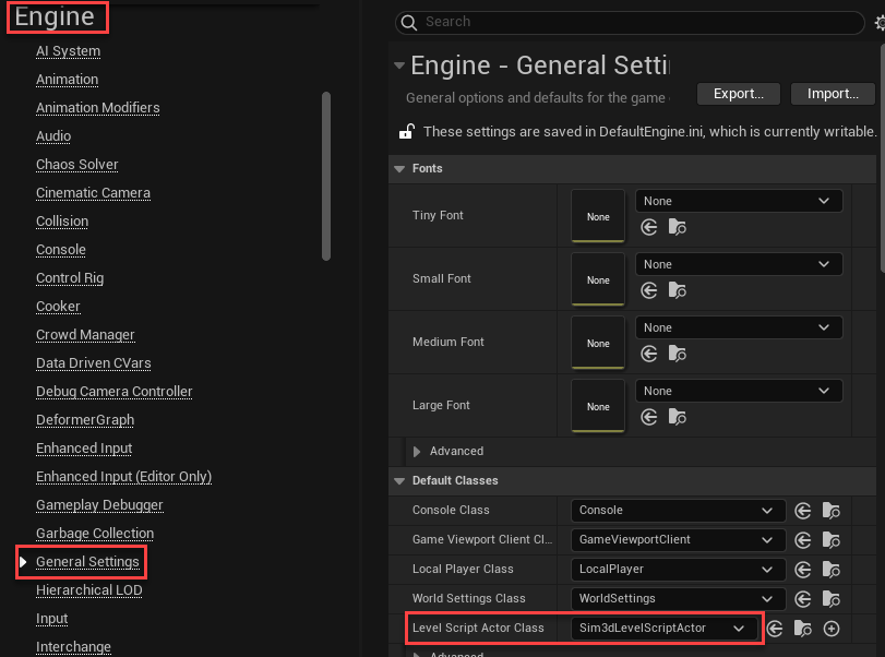
Select Engine, then click General Settings.
In the Default Classes section, set Level Script Actor Class to
Sim3dLevelScriptActor.Close Project Settings to save the default values, and reopen the editor from Simulink.
Set Default Game Mode
Note
You must complete this section if you use a custom project. If you are using the
AutoVrtlEnv project that comes installed with the UAV Toolbox
Interface for Unreal Engine Projects, skip this section.
If you use a custom project, you must set the default game mode of the project to use the default controls and features of the MathWorks Interface plugin. To set the default game mode, follow these steps:
Select Edit, then click Project Settings.
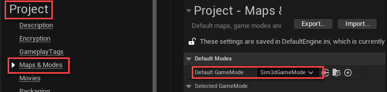
Select Project, then click Maps & Modes.
In the Default Modes section, set Default Game Mode to
Sim3dGameMode.Close Project Settings to save the default values and reopen the editor from Simulink.
Run Simulation
Follow these steps to run the simulation:
Open the Simulink model and click Run. After you click Run, the Simulink model remains in the initialization phase until you run the scene in Unreal Editor. Verify that the Diagnostic Viewer pane in Simulink displays this message:
In the Simulation 3D Scene Configuration block, you set the scene source to 'Unreal Editor'. In Unreal Editor, select 'Play' to view the scene.
This message confirms that Simulink has instantiated vehicles and other objects in the Unreal Engine 3D environment.
In the Unreal Editor, click Play to run the scene.
For an example of how to run a simulation using Simulink and Unreal Editor, see the Visualize VTOL UAV Takeoff and Forward Transition example.
To control the view of the scene during simulation, select a vehicle name from the Scene view parameter of the Simulation 3D Scene Configuration block. To change the scene view while in the Unreal Editor, during simulation, use the numeric keypad. For more details, see Navigate in Unreal Engine Environment.
To enable the numeric keypad when simulating a custom project, you must first copy the
DefaultInput.ini file from the support package installation
folder to your custom project folder. For example, copy
DefaultInput.ini from this location:
C:\ProgramData\MATLAB\SupportPackages\<MATLABRelease>\toolbox\shared\sim3dprojects\spkg\project\AutoVrtlEnv\Config
to this location:
C:\<yourproject>.project\Config