uavWaypointFollower
Follow waypoints for UAV
Description
The uavWaypointFollower
System object™ calculates a lookahead point, course, and yaw that enables a UAV to follow a
path, specified by a set of waypoints, based on the current UAV position and a specified
lookahead distance [1]. The object supports both
multirotor and fixed-wing UAV types.
To follow a set of waypoints:
Create the
uavWaypointFollowerobject and set its properties.Call the object with arguments, as if it were a function.
To learn more about how System objects work, see What Are System Objects?
Creation
Description
wpFollowerObj = uavWaypointFollower creates a UAV waypoint
follower with default properties.
wpFollowerObj = uavWaypointFollower(PropertyName=Value) sets
properties using one or more name-value arguments.
Properties
Usage
Description
[
determines a target position, lookaheadPoint,desiredCourse,desiredYaw,lookaheadDistFlag,crossTrackError,status,waypointIndex] = wpFollowerObj(currentPose,lookaheadDistance)lookaheadPoint, for the UAV on its path
to the next unvisited waypoint in the Waypoints property of the
uavWaypointFollower System object wpFollowerObj,
based on the specified current pose of the UAV currentPose and the
lookahead distance lookaheadDistance. The object also determines the
desired course, desired yaw, and cross track error of the UAV based on the target position
as compared to its current position, and indicates whether the specified lookahead
distance is valid and the UAV has already reached the final waypoint
Input Arguments
Output Arguments
Object Functions
To use an object function, specify the
System object as the first input argument. For
example, to release system resources of a System object named obj, use
this syntax:
release(obj)
Examples
Tune the parameters of a controllerVFH3D System object™ to navigate a multirotor UAV in an obstacle environment using a lidar sensor. Use the uavScenario object to create the obstacle environment. Mount a lidar sensor on the multirotor UAV to get the positions of obstacles. Use the uavWaypointFollower System object to set the goal location for the controllerVFH3D object. Use a PID controller to move the UAV in the desired obstacle-free direction.
Create Obstacle Scene Using UAV Scenario
Create a UAV scenario and set the simulation update rate to 2 Hz.
scene = uavScenario(UpdateRate=2);
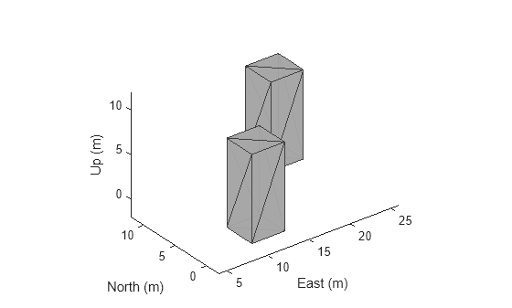
Add polygonal obstacle meshes to the scene.
polygonCorners1 = [8 -2;12 -2;12 2;8 2];
polygonCorners2 = [18 8;22 8;22 12;18 12];
polygonZRange = [0 10];
PolygonColor1 = [1 1 0];
PolygonColor2 = [0 0 1];
addMesh(scene,"polygon",{polygonCorners1,polygonZRange},PolygonColor1)
addMesh(scene,"polygon",{polygonCorners2,polygonZRange},PolygonColor2)
Visualize the scenario in 3D.
show3D(scene);
Create Multirotor Guidance Model and UAV Waypoint Follower
Create the multirotor UAV guidance model.
model = multirotor;
Create the waypoint follower. Set the UAV type, the transition radius for each waypoint, and the waypoints for the UAV to follow.
wf = uavWaypointFollower(UAVType="multirotor", ...
                         TransitionRadius=1, ...
                         Waypoints=[0 0 -5; 0 20 -5; 20 20 -5]);
Create UAV Platform and Mount Sensor
Specify the initial pose of the UAV.
uavPose = [0 0 -5 pi/2 0 0]';
Create a quadrotor platform using a north-east-down (NED) reference frame. Specify the initial position and orientation.
plat = uavPlatform("UAV",scene, ...
                   ReferenceFrame="NED", ...
                   InitialPosition=uavPose(1:3)', ...
                   InitialOrientation=eul2quat(uavPose(4:6)'));
Add a quadrotor mesh for visualization. Add a rotation to orient the mesh to the UAV body frame.
updateMesh(plat,"quadrotor",{1.5},[0 0 0],eul2tform([0 0 pi]))Create a statistical sensor model to generate point clouds for the lidar sensor.
lidarmodel = uavLidarPointCloudGenerator(AzimuthResolution=0.3324099, ...
                                         ElevationLimits=[-10 30], ...
                                         AzimuthLimits=[-60 60], ...
                                         ElevationResolution=0.5, ...
                                         MaxRange=10, ...
                                         UpdateRate=2, ...
                                         HasOrganizedOutput=true);
Create a lidar sensor, and mount the sensor on the quadrotor. Specify a mounting location for the sensor that is relative to the UAV body frame.
lidar = uavSensor("Lidar",plat,lidarmodel, ...
                  MountingLocation=[0 0 -0.4], ...
                  MountingAngles=[0 0 180]);
Set Up Simulation and Visualize Scenario
Visualize the scene. Remove edges from the floor mesh.
figure(1)
[ax,plotFrames] = show3D(scene);
ax.Children(end).LineStyle = "none";
Update the plot view for better visibility.
xlim(ax,[-10 40])
ylim(ax,[-10 40])
zlim(ax,[0 20])
view([-134.3 46.0])
axis(ax,"equal")
hold(ax,"on")

Configure controllerVFH3D Object and Integrate with Waypoint Follower
Create a controllerVFH3D object. Configure the HistogramResolution and MaxAge properties of the controllerVFH3D System object to improve obstacle avoidance. A low HistogramResolution value captures most of the obstacle points, but increases computation time. You can increase the MaxAge value to store obstacle points from previous time steps, enabling you to compute a stable obstacle-free direction, and better avoid local minima. Set the sensor-related parameters.
vfh3D = controllerVFH3D(HistogramResolution=5, ...
                        MaxAge=0, ...
                        HorizontalSensorFOV=lidarmodel.AzimuthLimits, ...
                        VerticalSensorFOV=lidarmodel.ElevationLimits, ...
                        SensorLocation=lidar.MountingLocation, ...
                        SensorOrientation=lidar.MountingAngles([3 2 1]));
The navigation logic uses two lookahead distances: one for the waypoint follower, and the other for the controllerVFH3D System object. The lookahead point for the waypoint follower is the target position for the controllerVFH3D System object. Compute the desired position for the PID controller from the desired direction output of the controllerVFH3D System object. A larger lookahead distance for the waypoint follower ensures that the target position is ahead of the desired position. This improves the tracking of the PID position controller.
Specify the lookahead distance for the desired point along an obstacle-free direction, and for the waypoint follower.
lookaheadOA = 2;
lookaheadWF = 6;
Set up the UAV initial state. The UAV state space consists of position, linear velocity, attitude Euler angles, angular velocity, thrust, and integral error.
uavPosition = uavPose(1:3);
uavOrientation = eul2quat(uavPose(4:6)')';
intErr = [0; 0; 0];
initialState = [uavPosition(1); uavPosition(2); uavPosition(3); ...
                0; 0; 0; uavPose(4); 0; 0; 0; 0; 0; 0; intErr];
Set the PID controller parameters.
kp = 15;
kd = 12;
ki = 0.005;
kyaw = 10;
Set the simulation start time, the number of simulation iterations, and the integration interval.
tStart = 0;
numIter = 200;
tStep = 0.1;
Create an empty time vector to store the time stamps of integration results
hStep = tStep/10;
tTotal = zeros(numIter*(tStep/hStep+1),1);
Create an empty states vector to store the simulation states. Number of states is equal to the number of model states plus integral error.
numStates = numel(model.state)+3;
states = zeros(numIter*(tStep/hStep+1),numStates);
Tune controllerVFH3D Object
To obtain the desired obstacle avoidance behavior, you must tune some of the properties of the controllerVFH3D System object.
Modify the obstacle avoidance algorithm behavior can be modified by changing the range sensor distance limits of the controllerVFH3D object.
vfh3D.DistanceLimits = [0.1 5];
Modify the path of the UAV by changing the weights associated with the target direction, previous direction, and desired direction.
vfh3D.TargetDirectionWeight = 5;
vfh3D.PreviousDirectionWeight = 2;
vfh3D.CurrentDirectionWeight = 2;
Modify the UAV radius and the safety distance properties to control the proximity of the UAV to the obstacles.
vfh3D.VehicleRadius = 0.5;
vfh3D.SafetyDistance = 0.5;
Simulate Obstacle Avoidance in UAV Scenario
Set up the simulation. Then, iterate through the positions and show the scene each time the lidar sensor updates. Advance the scene, move the UAV platform, and update the sensors.
setup(scene)

for idx = 1:numIter
    [isupdated,lidarSampleTime,pt] = read(lidar);
    xLidar = reshape(pt.Location(:,:,1),[],1);
    yLidar = reshape(pt.Location(:,:,2),[],1);
    zLidar = reshape(pt.Location(:,:,3),[],1);

    sensorPoints = [xLidar yLidar zLidar];

    [targetPosition,~,~] = wf(uavPose(1:4),lookaheadWF);

    [desiredDirection,desiredYaw,status] = vfh3D(uavPosition,uavOrientation, ...
                                                 sensorPoints,targetPosition);

    % Visualize the histogram.
    figure(2)
    show(vfh3D,PlotsToShow="2D Inflated Histogram");

    % Select the desired position along the obstacle-free direction.
    desiredPosition = uavPosition + lookaheadOA*desiredDirection;

    [t,y] = ode23(@(t,x)exampleHelperDerivative(t,x,model,desiredPosition,desiredYaw,kp,kd,ki,kyaw), ...
                  tStart:hStep:(tStart+tStep),initialState);

    % Store data.
    tTotal((idx-1)*(tStep/hStep+1) + 1:idx*(tStep/hStep+1)) = t;
    states((idx-1)*(tStep/hStep+1) + 1:idx*(tStep/hStep+1),:) = y;

    % Update states.
    uavPosition = y(end,1:3)';
    uavOrientEul = y(end,7:9)';
    uavOrientation = eul2quat(uavOrientEul')';
    tStart = t(end);
    initialState = y(end,:);

    % Plot the path.
    desPosition = plot3(desiredPosition(2),desiredPosition(1),-desiredPosition(3),".g",Parent=ax);
    tgtPosition = plot3(targetPosition(2),targetPosition(1),-targetPosition(3),".r",Parent=ax);
    goalPosition = plot3(wf.Waypoints(end,2),wf.Waypoints(end,1),-wf.Waypoints(end,3),"ob",Parent=ax);
    legend(ax,[desPosition tgtPosition goalPosition],["Desired Position","Target Position","Goal"])


    if isupdated
        % Use fast update to move platform visualization frames.
        show3D(scene,Parent=ax,Time=lidarSampleTime,FastUpdate=true);

        % Move the platform.
        move(plat,[uavPosition' y(end,4:6) zeros(1,3) eul2quat(uavOrientEul') zeros(1,3)]);
        drawnow limitrate
    end

    % Advance the scene simulation time.
    advance(scene);

    % Update all sensors in the scene.
    updateSensors(scene)

    uavPose = [uavPosition; quat2eul(uavOrientation',"ZYX")'];
end


Visualize Path
Visualize the path of the UAV through the environment.
figure(3)
plot3(states(:,2),states(:,1),-states(:,3))
title("UAV Path")
xlabel("East (m)")
ylabel("North (m)")
zlabel("Altitude (m)")

More About
When following a set of waypoints, the waypoint follower might ignore the first waypoint depending on the pose of the UAV. Each consecutive pair of waypoints forms a path segment, and the waypoint follower transitions to the next path segment if the UAV position satisfies at least one of these conditions:
The UAV is inside the transition region of the waypoint at the end of a segment.
The UAV is inside the 3D hyperplane region of the waypoint at the end of a segment
This behavior helps to ensure the UAV follows an achievable path.

The hyperplane condition is satisfied if:
p is the current UAV position. w1 is location of waypoint that starts the current path segment, and w2 is location of waypoint that ends the current path segment.
If you find this behavior limiting, consider adding more waypoints based on your initial pose to force the follower to navigate towards your initial waypoint.
References
[1] Park, Sanghyuk, John Deyst, and Jonathan How. “A New Nonlinear Guidance Logic for Trajectory Tracking.” Paper presented at AIAA Guidance, Navigation, and Control Conference and Exhibit, Providence, Rhode Island. AIAA Guidance, Navigation, and Control Conference and Exhibit, American Institute of Aeronautics and Astronautics, August 16, 2004. https://doi.org/10.2514/6.2004-4900.