Assign Interfaces to Ports
A port interface transmits data between ports in a System Composer™ architecture model. Data elements within the interface describe characteristics of the data transmitted across the interface. Data elements can describe the composition of a data interface, messages transmitted, or data structures shared between components.
Note
Connected ports in System Composer are compatible if they share a compatible interface type and structure. Ports without assigned interfaces automatically inherit from other ports on the connection. To activate compile-time checks for interface compatibility, on the toolstrip, click Update Diagram. You can reconcile incompatible interfaces on either end of a connection with an Adapter block using the Interface Adapter.
For interfaces terminology, see Define Port Interfaces Between Components.
This topic shows how to:
Assign data interfaces to a single port using the Property Inspector or multiple ports using the Interface Editor.
Manage owned interfaces that are local to a port and not shared in a data dictionary.
Assign interfaces to multiple ports at the same time.
Connect components through ports and specify the source element or the destination element for the connection.
Use the interface compatibility edit-time check.
To manage interfaces shared between models in data dictionaries, see Manage Interfaces with Data Dictionaries. For information on physical interfaces, see Specify Physical Interfaces on Ports.
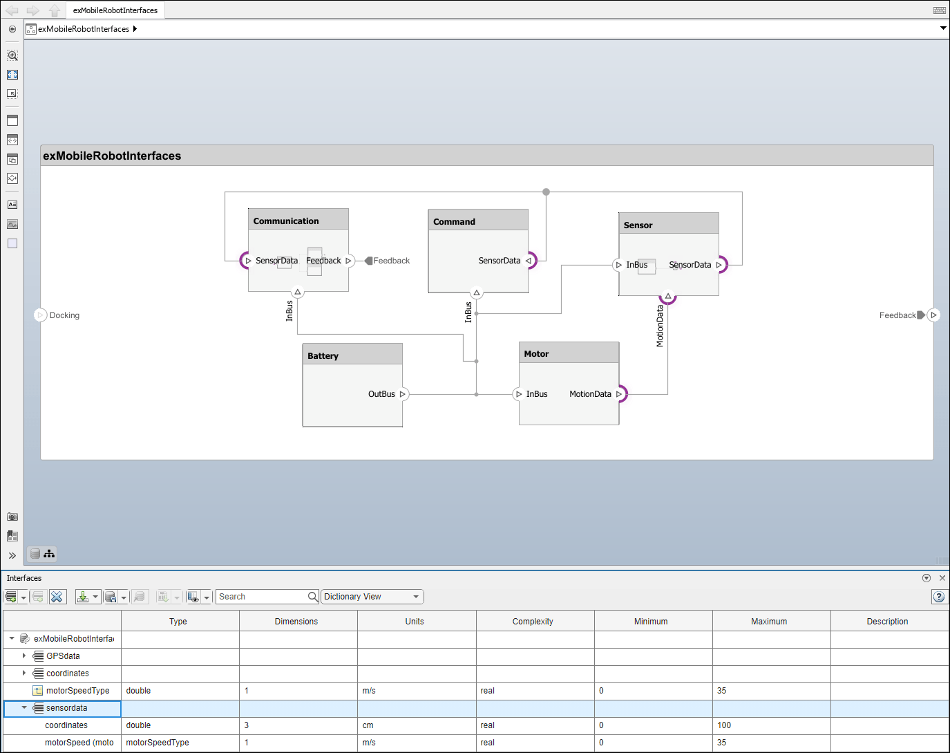
Mobile Robot Architecture Model with Interfaces
This example shows a mobile robot hardware architecture with interfaces defined.
Associate Ports with Interfaces in Property Inspector
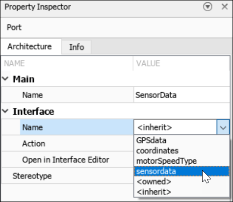
To assign data interfaces or value types to one port at a time, use the Property Inspector. To open the Property Inspector, navigate to Modeling > Property Inspector. To show the SensorData port properties, select the port in the model. Expand Interface, and from the Name list, select sensordata to associate the sensordata interface with the SensorData port.
Note
Newly created ports by default have an <inherit> interface
specification to support unknown interfaces in the early stages of architectural design. If
an interface is specified on another port, as you build your architecture, the
<inherit> specification propagates that interface to other
connected ports. Interface specifications do not automatically propagate through model and
subsystem references.
Assign Interfaces to Ports Using the Context Menu
After you select an interface from the Interface Editor, right-click a port. If the selected interface is compatible with the port, select Apply selected interface: <interface name> to assign the interface to the port. If a port already has an interface assigned, when you right click the port, you can select Clear interface: <interface name> to remove the interface.
After you select a port from the architecture canvas, right-click an interface on the Interface
Editor. To assign the interface to the port, select Assign to
selected port(s).
Note
You can apply stereotypes and assign interfaces to ports for a System Composer component linked to a Simulink® behavior model or subsystem through a Reference Component block. You must import the profile into the model or subsystem before applying a stereotype to the component. You must import a data dictionary into the model or subsystem before assigning interfaces to ports.
Define Owned Interfaces Local to Ports
Since R2021b
You can select a value type or data interface from the model data dictionary in the Property Inspector, or you can create an owned interface. An owned interface is an interface that is local to a specific port and not shared in a data dictionary or the model dictionary. Create an owned interface to represent a value type or data interface that is local to a port.
Note
Owned interfaces and value types do not have their own names because they are local to a port and not shared. The name of the owned interface is derived from the port name.
Manage Owned Interfaces Using Property Inspector
You can edit the data for the owned interface in the Property
Inspector. Select the Docking architecture port. In
the Property
Inspector, under Interface, from the
Name list, select <owned>.
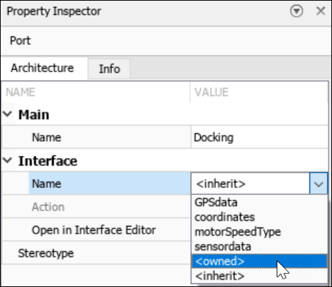
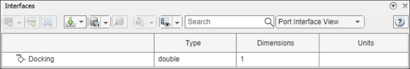
By default, the owned interface Docking becomes an owned value
type. Edit interface attributes directly in the Property
Inspector in the Parameters tab.
To convert the owned value type into an owned data interface, click ![]() to add a data element.
to add a data element.
Make Owned Interfaces into Shared Interfaces
To convert an owned interface into a shared interface, right-click the port with
the owned interface and select Convert to shared
interface. Alternatively, use the makeOwnedInterfaceShared function.
Select Multiple Ports and Assign Data Interface
Multiple ports, whether they are connected or not, can use the same data interface definition. When you assign a data interface to a port, the interface is automatically propagated to connected ports, provided they do not already have assignments. To simplify batch assignments, select multiple ports, right-click the data interface, and select Assign to selected port(s).
To highlight the ports that use a data interface definition, in the Interface Editor, right-click the interface name and select Highlight port(s) using this interface. To highlight only the source interfaces explicitly assigned to the ports, not including inherited interfaces on ports, select the interface in the Interface Editor.
Access Interface Elements Using Port Elements
A port element represents interface elements available on a port typed by a composite or owned interface. You can use port elements to access an element of a port by selecting the port name on the chevrons connected to root-level ports. When an interface element is typed by a composite interface, the nested port elements have two levels of hierarchy.
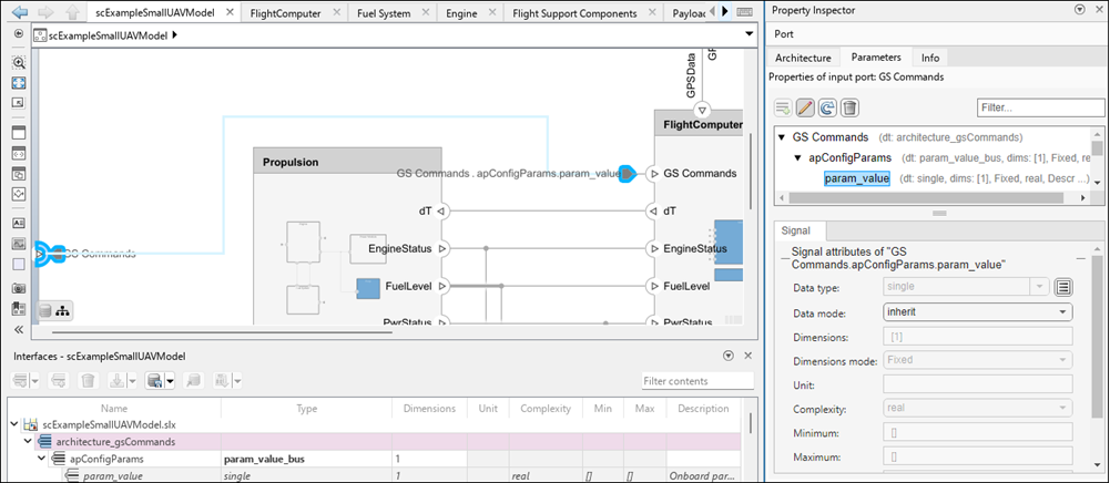
To open the small UAV project, enter this command in MATLAB®.
openExample('shared_systemsengineering/ModelingSystemArchitectureOfSmallUAVExample')You can access a port element on this architecture model of a small UAV. Assign the
architecture_gsCommands data interface to the GS
Commands port. Then, click the GS Commands chevron and select
the param_count port element. The Parameters tab
in the Property
Inspector shows the hierarchy of the interface and the port element.
For more information about the small UAV, see Modeling System Architecture of Small UAV.
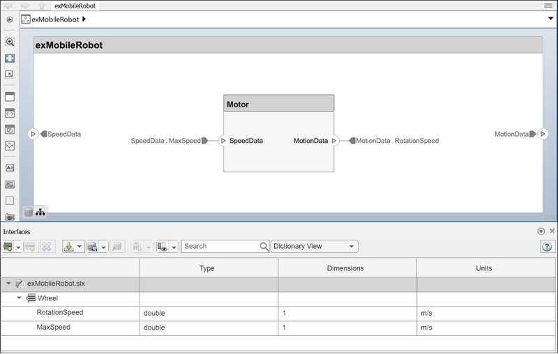
For connections between the root architecture and a component within the architecture model, you can add a source element or destination element to the ports.
Create a component called
Motorand connect it to the root architecture with ports namedMotionDataandSpeedData.Define the data interface
Wheelwith the data elementsRotationSpeedandMaxSpeed.Assign the
Wheeldata interface to the ports on the connection.Select the
MotionDataport name on the component. A dot and a list of data elements appear. From the list, select the source elementRotationSpeed.Assign the
MaxSpeeddestination element to theSpeedDataport.
When you link a Simulink behavior model to the Motor component, the port passes
only one element to the behavior model. The corresponding port in the behavior model
should receive the signal from the port element. For more information, see Transmit Signal Data Between Components Linked to Behavior Models.
Enable Interface Compatibility Edit-Time Check
Since R2022b
Edit-time checks report warnings as you build the model and require a Simulink Check™ license. Types of warnings for interface compatibility include:
Shared interfaces defined in a data dictionary are incompatible across ports on a connection if different interfaces are assigned to different ports.
Owned interfaces defined locally on ports are incompatible across ports on a connection if the value type or data elements do not have the same structure.
To enable edit-time checks on your architecture model, navigate to Modeling > Model Advisor > Edit-Time Checks. Select the Edit-Time Checks check box.
Connectors highlighted in yellow signify an interface mismatch between different ports on the same connector. If you click the warning symbol, you see the edit-time check message and a suggestion for what to do.
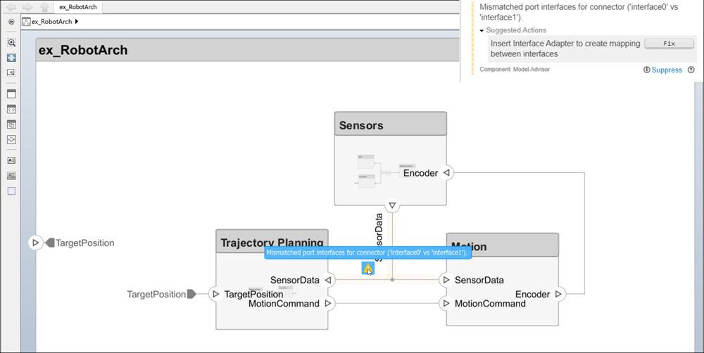
For incompatible interfaces on different ports on the same connection, such as different data interfaces, you can fix the problem by adding an Adapter block to define interface mappings.
For more information on creating your own custom edit-time checks, see Define Custom Edit-Time Checks That Fix Issues in Architecture Models (Simulink Check).
See Also
Functions
connect|getSubElement|getPortElement|getDestinationElement|getSourceElement|createOwnedType|createInterface|makeOwnedInterfaceShared