Collect Coverage for Variant Models During Simulation Using Variant Configurations
This example shows how to collect model coverage data for a variant model using predefined variant configurations.
You can use Simulink® Coverage™ to perform model and code coverage analysis that measures testing completeness in models and generated code. You can use missing coverage data to find gaps in testing, missing requirements, or unintended functionality. To learn the basic Simulink Coverage workflow, see Use Simulink Coverage to Analyze Your Model (Simulink Coverage).
Variant elements in Simulink, including variant blocks and variant parameters, enable you to represent multiple design alternatives within a single model. For such a model, you can define variant configurations to represent combinations of variant choices across the model hierarchy. These configurations comprise a set of variant control variables and their corresponding values, allowing you to activate specific variants within the model hierarchy. When you simulate a model containing one or more variant blocks with model coverage enabled, Simulink Coverage reports the coverage results depending on the type of variant block and the Variant activation time parameter. For more information, see Model Coverage for Variant Blocks (Simulink Coverage).
For models with predefined variant configurations, you can collect coverage data using variant configurations through one of these workflows:
Run programmatic simulations for a variant model by specifying variant configurations as input to the
Simulink.SimulationInputobject.Use Simulink Test Manager to run tests that use variant configurations.
Explore Example Model
Open the model slexVariantConfigsCoverage.
modelName = "slexVariantConfigsCoverage";
open_system(modelName);
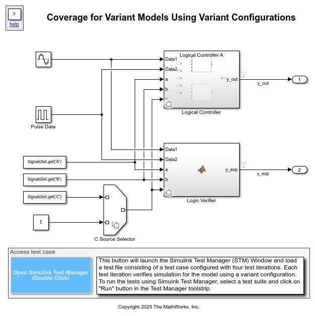
The model switches between a sine wave signal and a pulse signal based on three input signals A, B, and C. To switch the output, the model uses a Switch block. The two choices of the Variant Subsystem block, Logical Controller, implement variations in the logic used to switch the output with the Switch block. The variation is present in the logical expression built using the input signals A, B, and C, which acts as the control input to the Switch block.
The Logic Verifier Variant Subsystem block replicates the functionality of the Logical Controller block using MATLAB® code. This block employs two MATLAB Function blocks as its choices to implement the variations.
The Variant Source block C Source Selector allows you to read the data for signal C from a workspace or from a Constant block.
The model defines four variant configurations using Variant Manager. These configurations are stored in the variant configuration data object testConfigs, which is saved in the data dictionary dVariantConfigsCoverage.
Collect Coverage Using Simulink.SimulationInput object
The Simulink.SimulationInput
To collect coverage during a simulation, configure the Simulink.SimulationInput object to use the required variant configuration, enable coverage, and specify the required coverage metrics. The variant configuration is temporarily applied to the model, activating only the corresponding variant path in the model hierarchy before simulation.
This code shows how to collect Modified Condition/Decision Coverage (MCDC) (Simulink Coverage) by simulating the model for the predefined variant configuration CUsingConstConfig1.
1. Create a Simulink.SimulationInput object for the model.
simIn = Simulink.SimulationInput(modelName);
2. Enable coverage analysis.
simIn = simIn.setModelParameter("CovEnable","on");
3. Set the coverage metrics.
simIn = simIn.setModelParameter("CovMetricStructuralLevel","MCDC");
4. Enable the CovSaveSingleToWorkspaceVar parameter and set the name of the coverage data object to covData.
simIn = simIn.setModelParameter("CovSaveSingleToWorkspaceVar","on");
simIn = simIn.setModelParameter("CovSaveName","covData");
5. Set variant configuration property in the simIn object.
simIn = simIn.setVariantConfiguration("CUsingConstConfig1");
6. Simulate the model by using simIn as the input to sim.
simResults = sim(simIn);
7. When you simulate a model with coverage enabled, the system automatically generates a cvdata object. The SimulationOutput object contains this cvdata object in a property named after the CovSaveName parameter. In this example, extract the coverage data as a cvdata object from the SimulationOutput object simResults.
covData = simResults.covData;
8. You can access the coverage data from the cvdata object by using coverage functions. For example, view the execution coverage information for the From Workspace3 and Constant blocks by calling the executioninfo (Simulink Coverage) function with the block path.
fromWksBlkForC = modelName+"/From Workspace3";
constBlkForC = modelName + "/Constant";
execCovFromWks = executioninfo(covData,fromWksBlkForC)
execCovForConst = executioninfo(covData,constBlkForC)
execCovFromWks =

     0     1


execCovForConst =

     1     1
9. executioninfo returns an array with two scalars. The first value is the number of satisfied execution outcomes and the second value is the number of total execution outcomes. According to the definition of the variant configuration CUsingConstConfig1, the FromWorkspace3 block input to the C Source Selector block is disabled and the Constant block input is enabled during simulation. Thus, the value of execCovFromWks evaluates to [0 1] and execCovForConst evaluates to [1 1]. Use these values to determine the percentage of satisfied execution outcomes for the blocks.
pcCovFromWks = 100*execCovFromWks(1)/execCovFromWks(2)
pcCovForConst = 100*execCovForConst(1)/execCovForConst(2)
pcCovFromWks =

     0


pcCovForConst =

   100
10. View the condition coverage results for the Logical Controller A and Logical Controller B blocks in the Logical Controller variant subsystem by calling the conditioninfo (Simulink Coverage) function with the block path.
ctrlVSSPath = modelName+"/Logical Controller";
ctrlChoiceAPath = ctrlVSSPath+"/Logical Controller A";
ctrlChoiceBPath = ctrlVSSPath+"/Logical Controller B";
condCovLCA = conditioninfo(covData,ctrlChoiceAPath)
condCovLCB = conditioninfo(covData,ctrlChoiceBPath)
condCovLCA =

     6     8


condCovLCB =

     0    10
11. Compute the percentage of satisfied condition outcomes.
pcCovForLCA = 100*condCovLCA(1)/condCovLCA(2)
pcCovForLCB = 100*condCovLCB(1)/condCovLCB(2)
pcCovForLCA =

    75


pcCovForLCB =

     0
To find coverage for other variant configurations in a similar manner, change the variant configuration value in step 5 and repeat the remaining steps.
Collect Coverage Using Simulink Test Manager
Simulink® Test™ provides tools for authoring, managing, and executing systematic, simulation-based tests of models, generated code, and simulated or physical hardware. If you have a Simulink Test license, you can collect coverage directly from the Test Manager. For an example, see Analyze Model Coverage by Using the Test Manager in Simulink Test (Simulink Coverage).
The Test Manager also enables specification of variant configurations for test cases or test case iterations. For more information, see Run Tests for Variant Models Using Variant Configurations.
The slexVariantConfigsCoverage model has a baseline test case named Verify Controller Implementations, saved in the test file dVariantConfigsCoverage.mldatx. To launch the Test Manager and open the test file, double-click the Open Simulink Test Manager button in the model.
The test case sets up four iterations, each using one of the four predefined variant configurations. The test case enables coverage collection and selects the necessary metrics. Additionally, the test case verifies that y_out, the output of the Logical Controller block, matches y_exp, the output of the Logic Verifier block throughout the simulation.
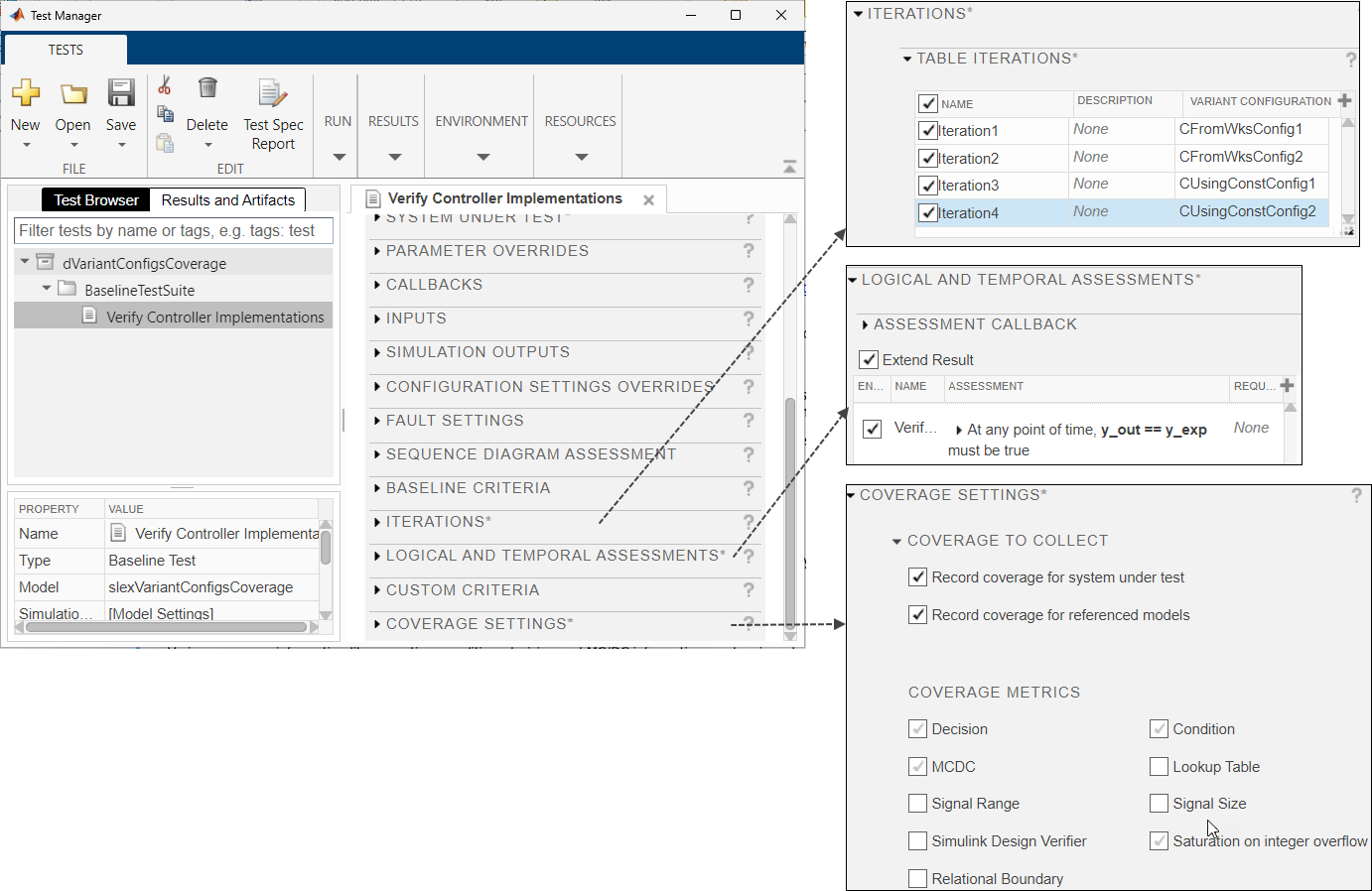
In the Test Manager, you can run individual tests or entire test suites. In the Test Browser pane, select the test case Verify Controller Implementations. In the Simulink Test Manager toolstrip, click Run to execute the test case.
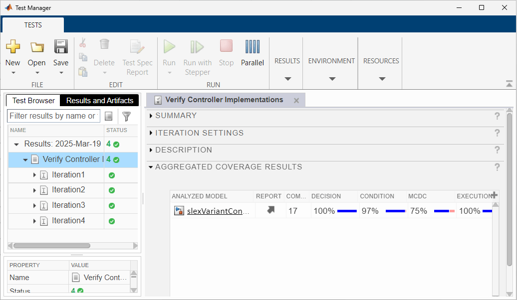
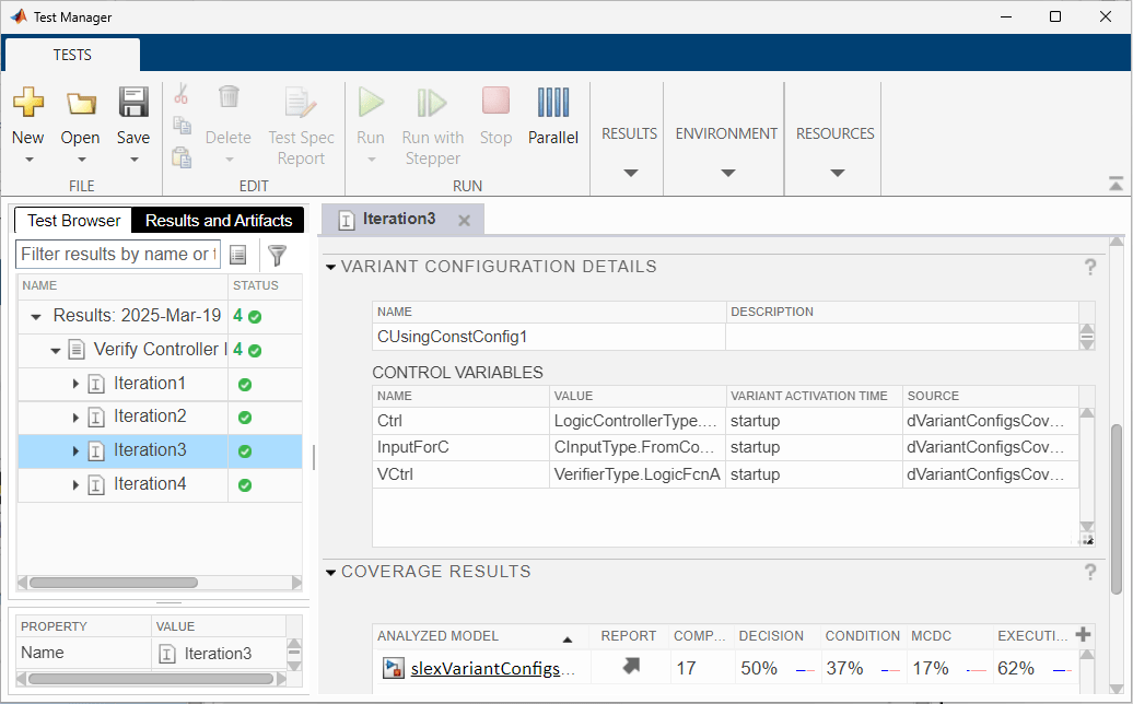
When the test finishes, the test case result appears in the Results and Artifacts pane. Click the most recent test run to see the aggregated coverage results. To see the coverage result for an iteration, select the iteration in the result.
These images show the aggregated coverage for the test case and the coverage for the test iteration Iteration3 which uses the configuration CUsingConstConfig1.
See Also
cvdata (Simulink Coverage) | Simulink.VariantConfigurationData