ブロックの接続
モデル内のブロック間の関係を確立するには、それらのブロックを接続します。
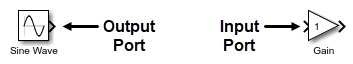
ほとんどのブロックは信号線を使用して接続できます。信号線はブロックの端子に接続されます。シミュレーション中に、信号は出力端子から接続された入力端子に移動します。
信号線を分岐させると、1 つのブロックの出力端子から複数のブロックの入力端子に信号を送信できます。
一部のブロックでは、ブロックの入力端子の数を変更できます。たとえば、同じグラフに複数の信号をプロットするには、Scope ブロックの入力端子の数を増やします。
信号線のレイアウト変更の詳細については、モデルのレイアウトの構成を参照してください。信号線にラベルを付ける方法の詳細については、モデル要素の名前とラベルの構成を参照してください。
信号をバンドルすることでブロック線図を簡略化できます。信号のバンドルの詳細については、バーチャル バスへの信号またはメッセージのグループ化を参照してください。
"関連するブロック" は、信号線を使用せずに接続されます。関連するブロックを接続する方法の詳細については、信号線を使用しないブロックの接続を参照してください。
信号線を使用したブロックの接続
信号線を使用して 2 つのブロックを接続するには、一方のブロックの出力端子にある端子シンボル  をクリックしてもう一方のブロックの入力端子にドラッグします。
次のショートカットを使用してブロックを接続できます。
信号線をドラッグせずにブロックを接続する場合:
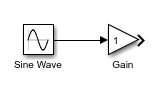
接続する出力端子と入力端子を垂直方向に整列して、それらの端子の間に他のコンポーネントを配置しないようにします。端子が既に整列している場合は、いずれかのブロックを移動して配置をずらしてから、再度整列します。端子を揃えるために移動したブロックを放すと、接続のプレビューが表示されます。

接続するには、プレビューをクリックします。
信号線をドラッグしたり端子を整列したりせずにブロックを接続する場合:
接続する出力端子の端子シンボルをクリックします。接続できる他のコンポーネントの入力端子に端子のヒント シンボル
 が表示されます。
接続のプレビューを表示するには、接続先にする入力端子の端子のヒント シンボルをポイントします。

接続するには、プレビューをクリックします。

信号線をドラッグしたり端子を整列したりせずに複数のブロックを単一のブロックに接続する場合:
たとえば、左クリックしながら選択ボックスをドラッグしてブロックを囲んで、出力端子を接続するブロックを選択します。
Ctrl キーを押しながら、入力端子を接続するブロックをクリックします。

ブロックの入力端子と出力端子の両方を既存の信号線に接続するには、ブロックをクリックして信号線にドラッグします。端子シンボル
が信号線上に置かれるようにブロックを配置します。出力端子シンボルが消えて、入力端子シンボルが塗りつぶされた矢印に変わったら、ポインターを放します。
信号線のセグメントを斜めにするには、Shift キーを押しながら、接続する頂点を別の信号線のセグメントにドラッグします。
単一の出力端子と複数の入力端子の接続
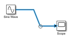
1 つの出力端子を複数の入力端子に接続するには、1 つの入力端子を出力端子に接続してから、信号線を分岐させて他の入力端子に接続します。
信号線を分岐させるには、Ctrl キーを押しながら既存の信号線をクリックして、接続するブロックの入力端子にドラッグします。
ヒント
線を分岐させるために、未接続の入力端子の端子シンボルをクリックして既存の信号線にドラッグすることもできます。

複数のブロックの出力端子と単一のブロックの接続
一部のブロックでは、その入力端子側に複数の信号線を接続できます。たとえば、1 つのグラフに複数の信号をプロットするには、複数のブロックの出力端子を単一の Scope ブロックに接続します。
複数のブロックの出力端子を単一のブロックに接続するには、接続する各出力端子から単一のブロックの入力端子側 (左端) に信号線をドラッグします。ブロック アイコンが青色に変わって端子番号が表示されたら、ポインターを放します。入力端子が自動的に作成され、信号線が接続されます。

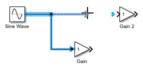
出力端子を接続するブロックがモデル内にまだない場合に、単一のブロックの入力端子の数を増やすには、以下を行います。
ポインターの横にプラス記号が表示されるまでブロックの入力端子側 (左端) をポイントします。

次に、ポインターをクリックしてドラッグし、ブロックから離します。別のブロックの出力端子に接続できる破線の信号線が表示されます。

入力端子を削除するには、その端子シンボルをクリックして Delete キーを押します。
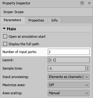
ブロックの入力端子の数を指定するには、[ブロック パラメーター] ダイアログ ボックスまたはプロパティ インスペクターの [パラメーター] タブを使用します。
ヒント
一部のブロックでは、モデルにブロックを追加するときに入力端子の数を入力できます。

サブシステムの接続
サブシステムに信号を送信するには、サブシステムに送信する信号と同じ数の入力端子がそのサブシステムに含まれている必要があります。
サブシステムから信号を受信するには、サブシステムから受信する信号と同じ数の出力端子がそのサブシステムに含まれている必要があります。
モデルに空のサブシステムを追加した場合、そのサブシステムには既定で入力端子と出力端子が 1 つずつ含まれています。
サブシステムを接続するには、以下を行います。
サブシステムを入力するには、Subsystem ブロックをダブルクリックします。

サブシステム内に、必要な数の入力端子と出力端子を追加します。

サブシステム内で、入力端子と出力端子をサブシステムに接続します。

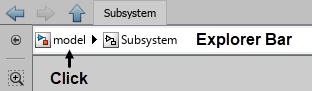
モデルの階層構造内で 1 つ上のレベルに移動するには、Simulink® キャンバスの上部にあるエクスプローラー バーで、Subsystem ブロックの名前の左にあるレベルの名前をクリックします。
サブシステムに送信する信号の信号線を Subsystem ブロックの入力端子に接続します。
Subsystem ブロックの各入力端子はサブシステム内の Inport ブロックに対応しています。Subsystem ブロックのどの入力端子がサブシステム内のどの Inport ブロックに対応しているかは、端子番号で判断できます。
サブシステムから受信する信号の信号線を Subsystem ブロックの出力端子に接続します。
Subsystem ブロックの各出力端子はサブシステム内の Outport ブロックに対応しています。

ヒント
サブシステムを手動で接続しないようにするには、Subsystem ブロックを追加するモデルの階層構造のレベルにサブシステムの内容を作成します。次に、この内容をサブシステムに変換します。
キャンバスでポインターをクリックしてドラッグし、コンポーネントを囲む四角形を描画することで、サブシステム コンポーネントを選択します。
表示される省略記号をポイントします。
展開された操作バーで、[サブシステムの作成] をクリックします。
サブシステムへの変換により、サブシステムの入力端子と出力端子が自動的に追加され、接続されます。
Subsystem への端子ブロックの接続
Subsystem ブロックに端子ブロックを接続すると、既定の端子名または要素名がカスタムの端子名または要素名に置き換えられます。
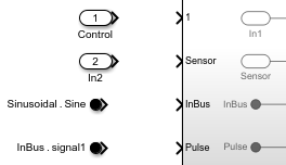
次のものがあるとします。
ControlとIn2という名前の Inport ブロックSinusoidal.SineとInBus.signal1というラベルが付けられた In Bus Element ブロックIn1、Sensor、InBus、およびPulseという名前の端子がある Subsystem ブロック
Subsystem ブロック アイコンに、既定の名前が In1 である Inport ブロックの端子番号が表示されます。
端子を接続すると次のようになります。
カスタム端子名が、対応する既定の端子名に置き換わります。たとえば、
Controlという名前の Inport ブロックを1というラベルが付けられたサブシステム端子に接続すると、サブシステム端子の名前および対応する Inport ブロックの名前が、In1からControlに変わります。同様に、In2という名前の Inport ブロックをSensorという名前のサブシステム端子に接続すると、Inport ブロックの名前が、In2からSensorに変わります。カスタム要素名が、対応する既定の端子名に置き換わります。たとえば、
Sinusoidal.Sineという名前の In Bus Element ブロックをInBusという名前のサブシステム端子に接続すると、サブシステム端子の名前が、InBusからSineに変わります。 (R2026a 以降)カスタム端子名が、対応する既定の要素名に置き換わります。たとえば、
InBus.signal1という名前の In Bus Element ブロックをPulseという名前のサブシステム端子に接続すると、In Bus Element ブロックの要素名が、signal1からPulseに変わります。 (R2026a 以降)

参照モデルが読み込まれている限り、Model ブロックの端子に接続する端子にも同じ動作が適用されます。Model ブロックの端子は影響を受けません。

信号線を使用しないブロックの接続
"関連するブロック" は、信号線を使用せずに相互に接続されます。
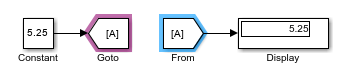
たとえば、Goto ブロックと From ブロックは、信号線を使用せずに信号を送信するために使用できる関連するブロックです。Goto ブロックに入る信号は、信号線を通過せずに From ブロックから出ます。
関連するブロックを接続するには、[ブロック パラメーター] ダイアログ ボックスまたはプロパティ インスペクターの [パラメーター] タブを使用します。
ヒント
2 つ以上の関連するブロックが接続されているかどうかを確認するには、いずれか 1 つを選択します。選択したブロックに接続されているすべての関連するブロックが紫色で強調表示されます。
関連するブロックの中には、タグを使用して接続されるものもあります。たとえば、同じタグをもつすべての Goto ブロックと From ブロックが接続されます。

これらのブロックのタグは、[ブロック パラメーター] ダイアログ ボックスまたはプロパティ インスペクターの [パラメーター] タブで設定できます。

Dashboard ライブラリと Customizable Blocks ライブラリのブロックも関連するブロックです。これらのライブラリの Display ブロックを信号に接続できます。制御ブロックをブロック パラメーターまたは変数に接続できます。Dashboard ブロックを接続する方法の詳細については、Connect Dashboard Blocks to Simulink Modelを参照してください。
信号線から Goto ブロックと From ブロックへの変換、およびその逆の変換
長い信号線を Goto ブロックと From ブロックに置き換えることで、モデルのブロック線図を簡略化できます。ただし、信号パスをトレースするときは、信号線を表示すると便利な場合があります。
信号線やバーチャル バスを Goto ブロックと From ブロックのセットに変換したり、Goto ブロックと From ブロックのセットを信号線に変換したりできます。Goto ブロックと From ブロックのセットは、接続されている Goto ブロックと From ブロックのグループです。つまり、これらのブロックは同じタグをもっています。
変換するモデル要素は次の条件を満たす必要があります。
信号線、バス、またはブロックが完全に接続されている。
信号線、バス、またはブロックがすべてモデルの階層構造内の同じ場所にある。つまり、すべてが階層構造の最上位レベルにあるか、すべてが同じコンポーネントにある。
信号線またはバスが Goto ブロックまたは From ブロックに接続されていない。
変換プロセス中に、これらの条件を満たしていないモデル要素は無視されます。変換は、ブロック タグが表示されているかどうかに関係なく実行できます。
Goto ブロックとその接続先のすべての From ブロックを信号線に変換するには、Goto ブロックを選択します。From ブロックとその接続先の Goto ブロックを信号線に変換するには、From ブロックを選択します。選択したブロックの上に表示される省略記号をポイントします。展開されたアクション メニューで、[信号に変換する] を選択します。あるいは、Goto ブロックまたは From ブロックを選択し、Simulink ツールストリップの [Goto] タブまたは [From] タブで、[信号に変換] をクリックします。

信号線またはバスを Goto ブロックと From ブロックのセットに変換するには、信号線またはバスを選択します。表示される省略記号をポイントします。展開されたアクション メニューで、[Goto ブロックと From ブロックに変換] を選択します。あるいは、信号線またはバスを選択し、ツールストリップの [信号] タブで、[Goto/From に変換] をクリックします。
複数の Goto ブロックとそれらに接続されたすべての From ブロックを信号線に同時に変換するには、Shift キーを押しながらブロックをクリックするか、ブロックを囲む選択ボックスをドラッグして、すべての Goto ブロックを選択します。Simulink ツールストリップの [Goto] タブで、[信号に変換] をクリックします。
Goto ブロックに同じタグをもつ複数の From ブロックがある場合に、From ブロックのサブセットを信号線に変換するには、変換する From ブロックを選択します。ツールストリップの [From] タブで、[信号に変換] をクリックします。選択した From ブロックが、対応する Goto ブロックから出る信号線に接続された信号線に変換されます。Goto ブロックは信号線に変換されません。
複数の信号線またはバスを Goto ブロックと From ブロックのセットに同時に変換するには、Shift キーを押しながらクリックするか、選択ボックスをドラッグして、信号線またはバスを選択します。ツールストリップの [信号] タブで、[Goto/From に変換] をクリックします。

ブロックのコメント アウトとコメント スルー
ブロックをモデルから物理的に削除せずにシミュレーションから除外するには、そのブロックをコメント アウトまたはコメント スルーします。
コメント アウト: 選択したブロックをシミュレーションから除外します。信号は打ち切られて接地されます。
コメント スルー: 選択したブロックをシミュレーションから除外します。信号は通過します。コメント スルーするには、ブロックに同じ数の入力端子と出力端子が含まれていなければならず、また、制御端子と接続端子が含まれていてはなりません。
メモ
次の Simulink ブロックのコメント アウトやコメント スルーはサポートされていません。
Inport
Outport
Connection Port
Argument Inport
Argument Outport
Data Store Memory
Goto Tag Visibility
Signal Generator ブロックのコメント スルーはサポートされていません。
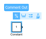
ブロックをコメント アウトするには、ブロックを選択します。表示された操作バーで、[コメント アウト] をクリックします。
ブロックをコメント スルーするには、ブロックを右クリックし、[コメント スルー] ボタン  をクリックします。
ヒント
あるいは、ブロックを選択して以下を押します。
コメント アウトするには Ctrl+Shift+X
コメント スルーするには Ctrl+Shift+Y