このページは機械翻訳を使用して翻訳されました。最新版の英語を参照するには、ここをクリックします。
NR NTN PDSCHスループット
この例では、3GPP NR 標準で定義されている非地上ネットワーク ( NTN)チャネルの 5G new radio (NR) リンクの物理ダウンリンク共有チャネル(PDSCH) スループットを測定する方法を示します。この例では、PDSCH とダウンリンク共有チャネル(DL-SCH) を実装します。送信機モデルには、PDSCH 復調参照信号 (DM-RS) と PDSCH 位相トラッキング参照信号 (PT-RS) が含まれます。この例では、 NTN狭帯域およびNTNタップ遅延線 (TDL) 伝搬チャネルがサポートされています。
はじめに
この例では、3GPP NR 標準 [1]、[2]、[3]、[4] で定義されている 5G リンクの PDSCH スループットを測定します。
この例では、次の 5G NR 機能をモデル化します。
DL-SCHトランスポートチャネル符号化
レイヤーの数に応じて複数のコードワード
PDSCH、PDSCH DM-RS、およびPDSCH PT-RSの生成
可変サブキャリア間隔とフレーム数
通常および拡張巡回プレフィックス
NTN狭帯域およびNTN TDL伝搬チャネルモデル
シミュレーションのその他の機能は次のとおりです。
特異値分解 (SVD) を使用した PDSCH プリコーディング。
巡回プレフィックス直交周波数分割多重化(CP-OFDM)変調。
スロット単位および非スロット単位の PDSCH と DM-RS のマッピング。
タイミング同期とチャネル推定。
キャリア全体にわたる単一の帯域幅部分 (BWP)。
送信機でのドップラー事前補償と受信機でのドップラー補償。
オプションのハイブリッド自動再送要求(HARQ) は最大 32 プロセスをサポートします。
オプションでメモリ付きとメモリなしのパワーアンプモデリングが可能。メモリ付きパワーアンプモデリングには RF Toolbox ™ が必要です。
オプションの静的および時間変動伝播遅延モデリング。
図は実装された処理チェーンを示しています。わかりやすくするために、DM-RS と PT-RS の生成は省略されています。

この例で実装されている手順の詳細な説明については、5G NR 通信リンクのモデル化 (5G Toolbox) および DL-SCH および PDSCH の送受信処理チェーン (5G Toolbox) を参照してください。
この例では、ワイドバンドおよびサブバンドのプリコーディングがサポートされています。SVD を使用して、割り当て内 (広帯域プリコーディングの場合) またはサブバンド内のすべての PDSCH PRB にわたるチャネル推定値を平均化することにより、プリコーディング マトリックスを決定します。
シミュレーションの合計時間を短縮するには、Parallel Computing Toolbox ™ を使用して、送信電力ループの送信電力値の範囲を並列に実行できます。
シミュレーションの長さ、送信機、受信機を構成する
シミュレーションの長さを 10 ミリ秒のフレームの数で設定します。この例ではデフォルトで 2 つのフレームが使用されていますが、意味のあるスループット結果を生成するには、多数の 10 ミリ秒のフレームが必要です。シミュレートする送信電力値の範囲を設定します。送信電力は、ドップラー事前補償を実行する前の時間領域波形の電力として定義され、電力増幅器のゲインが含まれます。受信機にはノイズ指数とアンテナ温度が含まれます。ノイズ指数は受信機の内部ノイズをモデル化し、アンテナ温度は入力ノイズをモデル化します。この受信機はアンテナ要素ごとのノイズを指定します。
simParameters = struct;                   % Create simParameters structure to
                                          % contain all key simulation parameters
simParameters.NFrames = 2;                % Number of 10 ms frames
simParameters.TxPower = 60:65;            % Transmit power (dBm)
simParameters.RxNoiseFigure = 6;          % Noise figure (dB)
simParameters.RxAntennaTemperature = 290; % Antenna temperature (K)
各送信電力ポイントでのスループット シミュレーションに関する情報を表示するには、displaySimulationInformation 変数を true に設定します。
displaySimulationInformation =  true;
true;パワーアンプの構成
この例では、メモリ型とメモリレス型の両方のパワーアンプモデリングがサポートされています。メモリ付きパワーアンプモデル化するには、この例では RF Toolbox ™ が必要です。
メモリまたはメモリレス電力増幅器の非線形性を構成するには、enablePA 変数を使用します。パワーアンプに渡される入力信号は、最大信号振幅を持つ正規化された信号です。
メモリレスパワーアンプ
TR 38.803 の付録 A で定義されているメモリレス パワー アンプ モデル (paModel) のいずれかを選択できます。
2.1 GHz ガリウムヒ素 (GaAs)
2.1 GHz 窒化ガリウム (GaN)
28 GHz 相補型金属酸化膜半導体 (CMOS)
28GHz GaN
あるいは、paModel を Custom に設定し、paCharacteristics 変数を使用して、メモリレス電力増幅器の特性を 3 列の行列として定義することもできます。最初の列は入力電力を dBm 単位で定義します。2 番目の列は出力電力を dBm 単位で定義します。3 番目の列は出力位相を度単位で定義します。paCharacteristics 変数を空に設定し、paModel を Custom に設定すると、この例では 2.1 GHz の横方向拡散金属酸化膜半導体 (LDMOS) Doherty ベースの増幅器が使用されます。
paModel を Custom 以外の値に設定すると、波形に適用されるメモリレス非線形性は、パワー アンプの次の式に従います。
この式では、
は出力信号です。
は入力信号です。
は多項式の次数の集合です。
は多項式の係数です。
メモリ付きパワーアンプ
波形にメモリを適用した場合の非線形性は、このメモリ多項式に従います。
この式では、
はメモリ多項式の深さです。
はメモリ多項式の次数です。
は多項式の係数です。
メモリ付きパワーアンプモデル化するには、hasMemory 変数を true に設定し、coefficients 変数を使用して多項式係数を指定します。coefficients 変数は、メモリ多項式の深さに対応する行数と、メモリ多項式の次数に対応する列数を持つ行列です。coefficients を空に設定すると、デフォルト値が適用されます。
デフォルトでは、この例では enablePA が false に設定されます。
enablePA =false; % true or false hasMemory =
false; % true or false paModel =
"2.1GHz GaAs"; % "2.1GHz GaAs", "2.1GHz GaN", "28GHz CMOS", "28GHz GaN", or "Custom" paCharacteristics = []; % Lookup table as empty or a matrix with columns: Pin (dBm) | Pout (dBm) | Phase (degrees) coefficients = []; % Memory polynomial coefficients
enablePA を true に設定すると、scaleFactor 変数を使用して最大入力信号振幅を変更し、パワー アンプの非線形性を励起します。scaleFactor はパワー アンプの動作領域を制御し、各送信アンテナに適用されます。scaleFactor 変数を使用して電力バックオフを設定することもできます。たとえば、パワー アンプを通過する信号に 3 dB のパワー バックオフを提供するには、scaleFactor を -3 に設定します。入力信号がパワーアンプ モデルの特性範囲内にあることを確認します。
scaleFactor が空の場合、この例ではデフォルト値の -35 dB が使用されます。
hasMemoryはfalse、paModelはCustom、paCharacteristicsは空です。hasMemoryはtrueであり、coefficientsは空です。
それ以外の場合、scaleFactor を空に設定すると、例ではデフォルト値の 0 dB が使用されます。
scaleFactor = []; % Amplitude scaling, in dBドップラー補正構成
この例では、送信機側と受信機側の 2 つのドップラー補正構成がサポートされています。送信機での補正には、DopplerPreCompensator を有効にします。DopplerPreCompensator フィールドを true に設定すると、送信波形にドップラー事前補正を適用して、衛星の動きによるドップラーを考慮します。受信側での補正には、RxDopplerCompensator フィールドを有効にします。RxDopplerCompensator フィールドを true に設定すると、巡回プレフィックスと参照信号を使用して、受信波形のドップラーシフトが推定され、補正されます。RxDopplerCompensator フィールドを true に設定すると、RxDopplerCompensationMethod フィールドを使用して受信機でドップラーを推定および補正する手法を選択できます。RxDopplerCompensationMethod フィールドは以下をサポートします:
独立した時間周波数同期 (
independent time-freq)。受信機は最初に周波数またはドップラーシフトを補正し、次にタイミングオフセットを補正します。共同時間周波数同期 (
joint time-freq)。受信機が周波数と時間の両方を同時に補正します。
デフォルトでは、この例では、ユーザー機器 (UE) が衛星ビームの中心にあると想定されています。ビーム中心以外の衛星ビーム内の UE をモデル化し (次の図を参照)、ビーム内のすべての UE に共通のドップラー シフト () を適用するには、PreCompensationDopplerShift フィールドを使用します。PreCompensationDopplerShift フィールドが空の場合、例では UE の衛星によるドップラーシフト () を として使用します。この例では、 が既知であると想定しています。PreCompensationDopplerShift フィールドが空でない場合のリンク パフォーマンスを観察するには、DopplerPreCompensator フィールドと RxDopplerCompensator フィールドの両方を true に設定する必要があります。DopplerPreCompensator を有効にすると が補正され、RxDopplerCompensator を有効にすると UE の移動によるドップラーシフトとともに残留衛星ドップラーシフト (-) が補正されます。

simParameters.DopplerPreCompensator =true; simParameters.PreCompensationDopplerShift = []; % In Hz simParameters.RxDopplerCompensator =
false; simParameters.RxDopplerCompensationMethod =
"independent time-freq"; % The example uses below fields to estimate Doppler shift, when % RxDopplerCompensator is set to true and RxDopplerCompensationMethod is % set to joint time-freq. % Set the search range of Doppler shift in Hz [MIN,MAX] simParameters.FrequencyRange = [-50e3 50e3]; % Set the search range resolution of Doppler shift in Hz simParameters.FrequencyResolution = 1e3;
初期タイミング同期アルゴリズムの選択
初期タイミング同期のアルゴリズムを選択します。
自己相関(
auto corr):受信機は、PDSCH DM-RS との自己相関を使用してタイミング同期を実行します。微分相関(
diff corr):受信機は、PDSCH DM-RS との差分相関を使用してタイミング同期を実行します。ジョイント時間周波数技術 (
joint time-freq):受信機は、初期周波数と初期タイミングを同時に補正してタイミング同期を実行します。
simParameters.InitialTimingSynchronization ="joint time-freq"; % The example uses below fields to perform initial synchronization, when % InitialTimingSynchronization is set to joint time-freq. % Set the initial search range of Doppler shift in Hz [MIN,MAX] simParameters.InitialFrequencyRange = [-50e3 50e3]; % Set the initial search range resolution of Doppler shift in Hz simParameters.InitialFrequencyResolution = 1e3;
キャリアとPDSCHの構成
シミュレーションの主要なパラメーターを設定します。これらのパラメーターには次のものが含まれます。
リソースブロック(RB)内の帯域幅
サブキャリア間隔(SCS)(kHz):15、30、60、120、240、480、または960
巡回プレフィックス長(CP):通常または拡張
セル ID
送信アンテナと受信アンテナの数
以下の DL-SCH および PDSCHパラメーターを含むサブ構造を作成します。
ターゲット符号化率
割り当てられたリソースブロック(PRBSet)
変調スキーム:QPSK、16QAM、64QAM、または256QAM
層の数
PDSCHマッピングタイプ
DM-RS 構成パラメーター
PT-RS 構成パラメーター
% Set waveform type and PDSCH numerology (SCS and CP type) simParameters.Carrier = nrCarrierConfig; simParameters.Carrier.SubcarrierSpacing =30; simParameters.Carrier.CyclicPrefix =
"Normal"; % Bandwidth in number of RBs (11 RBs at 30 kHz SCS for 5 MHz bandwidth) simParameters.Carrier.NSizeGrid = 11; % Physical layer cell identity simParameters.Carrier.NCellID =
1; % PDSCH/DL-SCH parameters % This PDSCH definition is the basis for all PDSCH transmissions in the % throughput simulation simParameters.PDSCH = nrPDSCHConfig; % This structure is to hold additional simulation parameters for the DL-SCH % and PDSCH simParameters.PDSCHExtension = struct(); % Define PDSCH time-frequency resource allocation per slot to be full grid % (single full grid BWP) % PDSCH PRB allocation simParameters.PDSCH.PRBSet = 0:simParameters.Carrier.NSizeGrid-1; % Starting symbol and number of symbols of each PDSCH allocation simParameters.PDSCH.SymbolAllocation = [0,simParameters.Carrier.SymbolsPerSlot]; simParameters.PDSCH.MappingType =
"A"; % Scrambling identifiers simParameters.PDSCH.NID = simParameters.Carrier.NCellID; simParameters.PDSCH.RNTI =
1; % PDSCH resource block mapping (TS 38.211 Section 7.3.1.6) simParameters.PDSCH.VRBToPRBInterleaving =
0; simParameters.PDSCH.VRBBundleSize =
4; % Define the number of transmission layers to be used simParameters.PDSCH.NumLayers =
1; % Define codeword modulation and target coding rate % The number of codewords is directly dependent on the number of layers so % ensure that layers are set first before getting the codeword number if simParameters.PDSCH.NumCodewords > 1 % Multicodeword transmission (when number of layers being > 4) simParameters.PDSCH.Modulation = [
"16QAM",
"16QAM"]; % Code rate used to calculate transport block sizes simParameters.PDSCHExtension.TargetCodeRate = [490 490]/1024; else simParameters.PDSCH.Modulation =
"16QAM"; % Code rate used to calculate transport block size simParameters.PDSCHExtension.TargetCodeRate = 490/1024; end % DM-RS and antenna port configuration (TS 38.211 Section 7.4.1.1) simParameters.PDSCH.DMRS.DMRSPortSet = []; % Use empty to auto-configure the DM-RS ports simParameters.PDSCH.DMRS.DMRSTypeAPosition =
2; simParameters.PDSCH.DMRS.DMRSLength =
1; simParameters.PDSCH.DMRS.DMRSAdditionalPosition =
2; simParameters.PDSCH.DMRS.DMRSConfigurationType =
2; simParameters.PDSCH.DMRS.NumCDMGroupsWithoutData =
1; simParameters.PDSCH.DMRS.NIDNSCID =
1; simParameters.PDSCH.DMRS.NSCID =
0; % PT-RS configuration (TS 38.211 Section 7.4.1.2) simParameters.PDSCH.EnablePTRS =
0; simParameters.PDSCH.PTRS.TimeDensity =
1; simParameters.PDSCH.PTRS.FrequencyDensity =
2; simParameters.PDSCH.PTRS.REOffset =
"00"; % PT-RS antenna port, subset of DM-RS port set. Empty corresponds to lowest % DM-RS port number simParameters.PDSCH.PTRS.PTRSPortSet = []; % Reserved PRB patterns, if required (for CORESETs, forward compatibility etc) simParameters.PDSCH.ReservedPRB{1}.SymbolSet = []; % Reserved PDSCH symbols simParameters.PDSCH.ReservedPRB{1}.PRBSet = []; % Reserved PDSCH PRBs simParameters.PDSCH.ReservedPRB{1}.Period = []; % Periodicity of reserved resources % Additional simulation and DL-SCH related parameters % PDSCH PRB bundling (TS 38.214 Section 5.1.2.3) simParameters.PDSCHExtension.PRGBundleSize = []; % 2, 4, or [] to signify "wideband" % Rate matching or transport block size (TBS) parameters % Set PDSCH rate matching overhead for TBS (Xoh) to 6 when PT-RS is enabled, otherwise 0 simParameters.PDSCHExtension.XOverhead = 6*simParameters.PDSCH.EnablePTRS; % HARQ parameters % Number of parallel HARQ processes to use simParameters.PDSCHExtension.NHARQProcesses =
1; % Enable retransmissions for each process, using redundancy version (RV) sequence [0,2,3,1] simParameters.PDSCHExtension.EnableHARQ = false; % LDPC decoder parameters % Available algorithms: Belief propagation, Layered belief propagation, % Normalized min-sum, Offset min-sum simParameters.PDSCHExtension.LDPCDecodingAlgorithm =
"Normalized min-sum"; simParameters.PDSCHExtension.MaximumLDPCIterationCount = 6; % Define the overall transmission antenna geometry at end-points % For NTN narrowband channel, only single-input-single-output (SISO) % transmission is allowed % Number of PDSCH transmission antennas (1,2,4,8,16,32,64,128,256,512,1024) >= NumLayers simParameters.NumTransmitAntennas = 1; if simParameters.PDSCH.NumCodewords > 1 % Multi-codeword transmission % Number of UE receive antennas (even number >= NumLayers) simParameters.NumReceiveAntennas = 8; else % Number of UE receive antennas (1 or even number >= NumLayers) simParameters.NumReceiveAntennas = 1; end % Define data type for resource grids and waveforms simParameters.DataType =
"double";
OFDM変調ステップ後のベースバンド波形に関する情報を取得します。
waveformInfo = nrOFDMInfo(simParameters.Carrier);
伝播チャネルモデルの構築
シミュレーション用のチャネルモデル オブジェクトを作成します。NTNナローバンド モデルとNTN TDLチャネルモデルの両方がサポートされています [5]、[6]。NTNナローバンド チャネルとNTN TDLチャネルをモデル化する方法の詳細については、モデルNR NTN チャネル を参照してください。
% Define the general NTN propagation channel parameters % Set the NTN channel type to Narrowband for an NTN narrowband channel and % set the NTN channel type to TDL for an NTN TDL channel. simParameters.NTNChannelType ="Narrowband"; % Include or exclude free space path loss simParameters.IncludeFreeSpacePathLoss =
true; % Delay model configuration % This example models only one-way propagation delay and provides immediate % feedback without any delay simParameters.DelayModel =
"None"; % "None", "Static", or "Time-varying" % Set the parameters common to both NTN narrowband and NTN TDL channels simParameters.CarrierFrequency = 2e9; % Carrier frequency (in Hz) simParameters.ElevationAngle = 50; % Elevation angle (in degrees) simParameters.MobileSpeed = 3*1000/3600; % Speed of mobile terminal (in m/s) simParameters.MobileAltitude = 0; % Mobile altitude (in m) simParameters.SatelliteAltitude = 600000; % Satellite altitude (in m) simParameters.SampleRate = waveformInfo.SampleRate; simParameters.RandomStream = "mt19937ar with seed"; simParameters.Seed = 73; simParameters.OutputDataType = simParameters.DataType; % Set the following fields for NTN narrowband channel if simParameters.NTNChannelType == "Narrowband" simParameters.Environment = "Urban"; simParameters.AzimuthOrientation = 0; end % Set the following fields for NTN TDL channel if simParameters.NTNChannelType == "TDL" simParameters.DelayProfile = "NTN-TDL-A"; simParameters.DelaySpread = 30e-9; end % Cross-check the PDSCH layering against the channel geometry HelperNRNTNThroughput.validateNumLayers(simParameters); % Calculate the Doppler shift due to satellite movement c = physconst("lightspeed"); satelliteDopplerShift = dopplerShiftCircularOrbit( ... simParameters.ElevationAngle,simParameters.SatelliteAltitude, ... simParameters.MobileAltitude,simParameters.CarrierFrequency); % Define NTN narrowband channel based on the specified fields in % simParameters structure if simParameters.NTNChannelType == "Narrowband" channel = p681LMSChannel; channel.Environment = simParameters.Environment; channel.AzimuthOrientation = simParameters.AzimuthOrientation; channel.CarrierFrequency = simParameters.CarrierFrequency; channel.ElevationAngle = simParameters.ElevationAngle; channel.MobileSpeed = simParameters.MobileSpeed; channel.SatelliteDopplerShift = satelliteDopplerShift; end % Define NTN TDL channel based on specified fields in simParameters % structure if simParameters.NTNChannelType == "TDL" channel = nrTDLChannel; channel.DelayProfile = simParameters.DelayProfile; channel.DelaySpread = simParameters.DelaySpread; channel.SatelliteDopplerShift = satelliteDopplerShift; channel.MaximumDopplerShift = ... simParameters.MobileSpeed*simParameters.CarrierFrequency/c; channel.NumTransmitAntennas = simParameters.NumTransmitAntennas; channel.NumReceiveAntennas = simParameters.NumReceiveAntennas; end % Assign the parameters common to both TDL and narrowband channels channel.SampleRate = simParameters.SampleRate; channel.RandomStream = simParameters.RandomStream; channel.Seed = simParameters.Seed; % Get the maximum number of delayed samples due to a channel multipath % component. The maximum number of delayed samples is calculated from the % channel path with the maximum delay and the implementation delay of the % channel filter. This number of delay samples is required later to buffer % and process the received signal with the expected length. chInfo = info(channel); maxChDelay = ceil(max(chInfo.PathDelays*channel.SampleRate)) + ... chInfo.ChannelFilterDelay;
処理ループ
各送信電力ポイントでのスループットを決定するには、次の手順に従って各送信インスタンスの PDSCH データを解析します。
トランスポート ブロックの生成 — PDSCH 構成に応じて各コードワードのトランスポート ブロック サイズを取得します。指定された HARQ プロセスの送信ステータスに応じて、各送信に対して新しいトランスポート ブロックを生成します。
リソース グリッドを生成します —
nrDLSCH(5G Toolbox) System object ™ はトランスチャネルコーディングを実行します。オブジェクトは入力トランスポート ブロックで動作します。nrPDSCH(5G Toolbox) 関数はエンコードされたデータ ビットを変調します。実装固有の複数入力複数出力 (MIMO) プリコーディングを変調シンボルに適用します。これらの変調シンボルを参照信号とともにリソース グリッドにマップします。波形の生成 —
nrOFDMModulate(5G Toolbox) 関数は、生成されたリソース グリッドの OFDM変調を実行して、時間領域の波形を提供します。各アンテナの最大波形振幅で波形を正規化します。パワーアンプの非線形性を適用する — 入力スケーリング係数に応じて正規化された波形の振幅をスケーリングします。メモリまたはメモリレス電力増幅器の非線形性をベースバンド OFDM 波形に適用します。波形電力を希望の送信電力に合わせて調整します。
ドップラー事前補正を適用する — 生成された波形に衛星の移動によるドップラーシフトを適用し、チャネルによって誘発される衛星ドップラーシフトを事前補正します。
ノイズの多いチャネルをモデル化して適用する — 伝播レイテンシに応じて生成された波形を遅延させます。遅延波形をNTNナローバンドまたはNTN TDL フェージングチャネルに渡して、フェードされた波形を取得します。パス ロスを適用し、フェードされた波形に熱ノイズを追加します。
初期同期を実行する — エネルギー検出を使用して信号の存在を確認します。エネルギー検出後、受信波形は初期スロットの PDSCH DM-RS を使用して初期タイミング オフセットを取得します。初期同期が達成されるまでこの手順を実行します。
ドップラー補正を適用する — 受信波形のドップラーシフトを推定し、ドップラーシフトを補正します。
同期と OFDM 復調を実行する — タイミング同期のために、受信波形は PDSCH DM-RS と相関されます。次に、
nrOFDMDemodulate(5G Toolbox) 関数が同期信号を OFDM 復調します。チャネル推定を実行する -チャネル推定には、PDSCH DM-RS が使用されます。
イコライゼーションと CPE 補正を実行する —
nrEqualizeMMSE(5G Toolbox) 関数は、受信した PDSCH RE をイコライゼーションします。PT-RS シンボルを使用して共通位相誤差 (CPE) を推定し、参照 PT-RS OFDM シンボルの範囲内で各 OFDM シンボルの誤差を修正します。プリコーディング行列の計算 — SVD を使用して、次の送信用のプリコーディング行列 W を生成します。
PDSCH をデコードする —
nrPDSCHDecode(5G Toolbox) 関数を使用して、等化された PDSCH シンボルを復調およびデスクランブルし、ノイズ推定値とともに受信コードワードの推定値を取得します。DL-SCH をデコードする— デコードされたソフト ビットを
nrDLSCHDecoder(5G Toolbox) System object に渡します。オブジェクトはコードワードをデコードし、ブロック巡回冗長検査 (CRC) エラーを返します。CRC エラーで HARQ プロセスを更新します。この例では、CRC エラーを使用して PDSCH リンクのスループットを決定します。
% Compute the noise amplitude per receive antenna
kBoltz = physconst("boltzmann");
NF = 10^(simParameters.RxNoiseFigure/10);
T0 = 290;                                               % Noise temperature at the input (K)
Teq = simParameters.RxAntennaTemperature + T0*(NF-1);   % K
N0_ampl = sqrt(kBoltz*waveformInfo.SampleRate*Teq/2.0);

% Number of transmit power points
numTxPowerPoints = length(simParameters.TxPower);
% Array to store the maximum throughput for all transmit power points
maxThroughput = zeros(numTxPowerPoints,1);
% Array to store the simulation throughput for all transmit power points
simThroughput = zeros(numTxPowerPoints,1);
% Array to store the signal-to-noise ratio (SNR) for all transmit power points
snrVec = zeros(numTxPowerPoints,1);

% Common Doppler shift for use in the simulations
if isempty(simParameters.PreCompensationDopplerShift)
    commonDopplerShift = satelliteDopplerShift;
else
    commonDopplerShift = simParameters.PreCompensationDopplerShift;
end

% Set up RV sequence for all HARQ processes
if simParameters.PDSCHExtension.EnableHARQ
    % In the final report of RAN WG1 meeting #91 (R1-1719301), it was
    % observed in R1-1717405 that if performance is the priority, [0 2 3 1]
    % should be used. If self-decodability is the priority, it should be
    % taken into account that the upper limit of the code rate at which
    % each RV is self-decodable is in the following order: 0>3>2>1
    rvSeq = [0 2 3 1];
else
    % In case of HARQ disabled, RV is set to 0
    rvSeq = 0;
end

% Create DL-SCH encoder System object to perform transport channel encoding
encodeDLSCH = nrDLSCH;
encodeDLSCH.MultipleHARQProcesses = true;
encodeDLSCH.TargetCodeRate = simParameters.PDSCHExtension.TargetCodeRate;

% Create DL-SCH decoder System object to perform transport channel decoding
decodeDLSCH = nrDLSCHDecoder;
decodeDLSCH.MultipleHARQProcesses = true;
decodeDLSCH.TargetCodeRate = simParameters.PDSCHExtension.TargetCodeRate;
decodeDLSCH.LDPCDecodingAlgorithm = simParameters.PDSCHExtension.LDPCDecodingAlgorithm;
decodeDLSCH.MaximumLDPCIterationCount = ...
    simParameters.PDSCHExtension.MaximumLDPCIterationCount;

% Initialize objects to model delay
tmpInfo = HelperNRNTNThroughput.initializeDelayObjects(simParameters,waveformInfo);
staticDelay = tmpInfo.StaticDelay;
variableIntegerDelay = tmpInfo.VariableIntegerDelay;
variableFractionalDelay = tmpInfo.VariableFractionalDelay;
maxVarPropDelay = tmpInfo.MaxVariablePropDelay;
numVariableIntegSamples = tmpInfo.NumVariableIntegerDelaySamples;
numVariableFracDelaySamples = tmpInfo.NumVariableFractionalDelaySamples;
delayInSeconds = tmpInfo.DelayInSeconds;
pathLoss = tmpInfo.PathLoss;
SU = tmpInfo.SlantDistance;

% Get the starting time of each slot
[slotTimes,symLen] = HelperNRNTNThroughput.getSlotTimes( ...
    simParameters.Carrier.SymbolsPerSlot,waveformInfo.SymbolLengths, ...
    waveformInfo.SampleRate,simParameters.NFrames,simParameters.DataType);

% Check the number of HARQ processes and initial propagation delay
initialSlotDelay = find(slotTimes>=delayInSeconds(1),1)-1;
if simParameters.PDSCHExtension.EnableHARQ
    if simParameters.PDSCHExtension.NHARQProcesses < initialSlotDelay
        error("In case of HARQ, this example supports transmission of continuous data only. " + ...
            "Set the number of HARQ processes (" + (simParameters.PDSCHExtension.NHARQProcesses) +...
            ") to a value greater than or equal to the maximum propagation delay in slots (" + ...
            initialSlotDelay +").")
    end
end

% Initial frequency shift search space
if simParameters.InitialTimingSynchronization == "joint time-freq"
    inifVals = simParameters.InitialFrequencyRange(1):simParameters.InitialFrequencyResolution:simParameters.InitialFrequencyRange(2);
else
    inifVals = 0;
end

% Frequency shift search space
if simParameters.RxDopplerCompensator == 1 ...
        && simParameters.RxDopplerCompensationMethod == "joint time-freq"
    fVals = simParameters.FrequencyRange(1):simParameters.FrequencyResolution:simParameters.FrequencyRange(2);
else
    % In case of no receiver Doppler compensation, treat the frequency
    % value is 0 Hz.
    fVals = 0;
end

% Initialize the power amplifier function handle or System object depending
% on the input configuration
[hpa,hpaDelay,paInputScaleFactor] = ...
    HelperNRNTNThroughput.initializePA(paModel,hasMemory,paCharacteristics,coefficients);

% Repeat hpa to have independent processing for each antenna
hpa = repmat({hpa},1,simParameters.NumTransmitAntennas);

% Update the power amplifier input scaling factor, based on scaleFactor
if ~isempty(scaleFactor)
    paInputScaleFactor = scaleFactor;
end

% Set a threshold value to detect the valid OFDM symbol boundary. For a
% SISO case, a threshold of 0.48 can be used to have probability of
% incorrect boundary detection around 0.01. Use 0 to avoid thresholding
% logic.
dtxThresold = 0.48;

% Use an offset to account for the common delay. The example, by default,
% does not introduce any common delay and only passes through the channel.
sampleDelayOffset = 0; % Number of samples

% Set usePreviousShift variable to true, to use the shift value estimated
% in first slot directly for the consecutive slots. When set to false, the
% shift is calculated for each slot, considering the range of shift values
% to be whole cyclic prefix length. This is used in the estimation of
% integer Doppler shift.
usePreviousShift = false;

% Set useDiffCorr variable to true, to use the shift estimated from
% differential correlation directly in the integer Doppler shift
% estimation. When set to false, the range of shift values also include the
% shift estimated from differential correlation.
useDiffCorr = true;

% Set the amplitude scaling factor to use in energy detection. For the
% default case, a factor of 1.03 is used to avoid missed detections at 60
% dBm transmit power. A value of 0 assumes each sample is an actual signal.
amplThreshold = 1.03;

% Use the minimum number of samples for a slot in the whole frame as
% window length
mrms = dsp.MovingRMS;
slotsPerSubFrameFlag = simParameters.Carrier.SlotsPerSubframe > 1;
mrms.WindowLength = symLen((1+(slotsPerSubFrameFlag))*simParameters.Carrier.SymbolsPerSlot) ...
    -slotsPerSubFrameFlag*symLen(simParameters.Carrier.SymbolsPerSlot);

% Processing loop
for txPowIdx = 1:numTxPowerPoints     % Comment out for parallel computing
% parfor txPowIdx = 1:numTxPowerPoints % Uncomment for parallel computing
    % To reduce the total simulation time, you can execute this loop in
    % parallel by using Parallel Computing Toolbox features. Comment
    % out the for-loop statement and uncomment the parfor-loop statement.
    % If Parallel Computing Toolbox is not installed, parfor-loop defaults
    % to a for-loop statement. Because the parfor-loop iterations are
    % executed in parallel in a nondeterministic order, the simulation
    % information displayed for each transmit power point can be intertwined.
    % To switch off the simulation information display, set the
    % displaySimulationInformation variable (defined earlier in this
    % example) to false.

    % Reset the random number generator so that each transmit power point
    % experiences the same noise realization
    rng(0,"twister");

    % Make copies of the simulation-level parameter structures so that they
    % are not Parallel Computing Toolbox broadcast variables when using parfor
    simLocal = simParameters;
    waveinfoLocal = waveformInfo;

    % Make copies of channel-level parameters to simplify subsequent
    % parameter referencing
    carrier = simLocal.Carrier;
    rxCarrier = carrier;
    pdsch = simLocal.PDSCH;
    pdschextra = simLocal.PDSCHExtension;
    % Copy of the decoder handle to help Parallel Computing Toolbox
    % classification
    decodeDLSCHLocal = decodeDLSCH;
    decodeDLSCHLocal.reset();       % Reset decoder at the start of each transmit power point

    % Make copies of intermediate variables to have warning-free execution
    % with Parallel Computing Toolbox
    thres = dtxThresold;
    sampleOffset = sampleDelayOffset;
    usePrevShift = usePreviousShift;
    useDiffCorrFlag = useDiffCorr;
    N0 = N0_ampl;
    pl_dB = pathLoss;
    varIntegSamples = numVariableIntegSamples;
    varFracSamples = numVariableFracDelaySamples;
    fValsVec = fVals;
    inifValsVec = inifVals;
    threshFactor = amplThreshold;
    initialDelay = initialSlotDelay;
    preDopplerShift = commonDopplerShift;

    % Initialize temporary variables
    offset = 0;
    shiftOut = 0;
    txHarqProc = 0;
    rxHarqProc = 0;
    prevWave = [];
    pathFilters = [];
    rxBuff = [];
    syncCheck = true;

    % Reset the channel so that each transmit power point experiences the
    % same channel realization
    reset(channel);

    % Reset the power amplifier
    for numHPA = 1:numel(hpa)
        if ~isa(hpa{numHPA},"function_handle")
            reset(hpa{numHPA})
        end
    end

    % Reset the delay objects
    reset(staticDelay)
    if isa(variableIntegerDelay,"dsp.VariableIntegerDelay")
        reset(variableIntegerDelay)
    end
    if isa(variableFractionalDelay,"dsp.VariableFractionalDelay")
        reset(variableFractionalDelay)
    end

    % Reset the moving RMS object
    reset(mrms)

    % Transmit power value in dBm
    txPowerdBm = simLocal.TxPower(txPowIdx);

    % Specify the order in which we cycle through the HARQ process
    % identifiers
    harqSequence = 0:pdschextra.NHARQProcesses-1;

    % Initialize the state of all HARQ processes
    % Create a parallel array of all HARQ processes
    harqEntity = cell(pdschextra.NHARQProcesses,1);
    for harqId = 1:pdschextra.NHARQProcesses
        harqEntity{harqId} = HARQEntity(harqSequence(harqId),rvSeq,pdsch.NumCodewords);
    end

    % Total number of slots in the simulation period
    NSlots = simLocal.NFrames*carrier.SlotsPerFrame;

    % Obtain a precoding matrix (wtx) to use in the transmission of the
    % first transport block
    [estChannelGrid,sampleTimes] = HelperNRNTNThroughput.getInitialChannelEstimate(...
        carrier,simLocal.NumTransmitAntennas,channel,simLocal.DataType);
    newWtx = HelperNRNTNThroughput.getPrecodingMatrix( ...
        carrier,pdsch,estChannelGrid,pdschextra.PRGBundleSize);

    % Loop over the entire waveform length
    for nslot = 0:NSlots-1

        % Update carrier slot number to account for new slot transmission
        carrier.NSlot = nslot;

        % Calculate the transport block sizes for the transmission in the slot
        trBlkSizes = nrTBS(pdsch,pdschextra.TargetCodeRate,pdschextra.XOverhead);

        % Set transport block depending on the HARQ process
        for cwIdx = 1:pdsch.NumCodewords
            % Create a new DL-SCH transport block for new data in the
            % current process
            if harqEntity{txHarqProc+1}.NewData(cwIdx)
                trBlk = randi([0 1],trBlkSizes(cwIdx),1,'int8');
                setTransportBlock(encodeDLSCH,trBlk,cwIdx-1,harqEntity{txHarqProc+1}.HARQProcessID);
                % Flush decoder soft buffer explicitly for any new data
                % because of previous RV sequence time out
                if harqEntity{txHarqProc+1}.SequenceTimeout(cwIdx)
                    resetSoftBuffer(decodeDLSCHLocal,cwIdx-1,harqEntity{txHarqProc+1}.HARQProcessID);
                end
            end
        end

        % Get precoding matrix (wtx) calculated in previous slot
        wtx = newWtx;

        % Create a structure with transport block encoder
        dlsch = struct;
        dlsch.Encoder = encodeDLSCH;
        dlsch.RedundancyVersion = harqEntity{txHarqProc+1}.RedundancyVersion;
        dlsch.HARQProcessID = harqEntity{txHarqProc+1}.HARQProcessID;

        % Generate time-domain waveform
        txWaveform0 = HelperNRNTNThroughput.generatePDSCHWaveform( ...
            carrier,pdsch,dlsch,wtx,simLocal.DataType);

        % Normalize the waveform with maximum waveform amplitude
        txWaveform = txWaveform0./max(abs(txWaveform0));

        % Adjust the waveform amplitude and pass the waveform through power
        % amplifier
        if (enablePA == 1)
            % Scale the amplitude of the waveform, as applicable
            txWaveform = txWaveform.*db2mag(paInputScaleFactor);

            % Pass the adjusted waveform through the power amplifier
            for colIdx = 1:size(txWaveform,2)
                hpaTemp = hpa{colIdx};
                txWaveform(:,colIdx) = hpaTemp(txWaveform(:,colIdx));
            end
        end

        % Scale the waveform power based on the input transmit power
        wavePower = 10*log10(sum(var(txWaveform)));
        powerScaling = (txPowerdBm-30)-wavePower;      % In dB
        txWaveform = db2mag(powerScaling)*txWaveform;

        % Apply Doppler pre-compensation depending on DopplerPreCompensator
        % field
        txWaveform = HelperNRNTNThroughput.compensateDopplerShift(...
            txWaveform,channel.SampleRate, ...
            preDopplerShift,simLocal.DopplerPreCompensator);

        % Apply path loss to the signal
        txWaveform = txWaveform*db2mag(-pl_dB(carrier.NSlot+1));

        % Apply fixed or static delay
        delayedTx = staticDelay(txWaveform);
        % Apply variable integer delay
        if isa(variableIntegerDelay,"dsp.VariableIntegerDelay")
            delayedTx = variableIntegerDelay(delayedTx,varIntegSamples(carrier.NSlot+1));
        end
        % Apply variable fractional delay
        if isa(variableFractionalDelay,"dsp.VariableFractionalDelay")
            delayedTx = variableFractionalDelay(delayedTx,varFracSamples(carrier.NSlot+1));
        end

        % Pass the waveform through the channel
        txWaveform = delayedTx;
        [rxWaveform,pathGains] = channel(txWaveform);

        % Add thermal noise to the received time-domain waveform. Multiply
        % the noise variance with 2 as wgn function performs the scaling
        % within.
        noise = wgn(size(rxWaveform,1),size(rxWaveform,2),2*(N0^2),1,"linear","complex");
        sigPowerRE = sum(var(rxWaveform))*((waveinfoLocal.Nfft)^2/(carrier.NSizeGrid*12));
        noisePowerRE = sum(var(noise))*(waveinfoLocal.Nfft);
        snrVec(txPowIdx) = snrVec(txPowIdx) + sigPowerRE./noisePowerRE;
        rxWaveform = rxWaveform + cast(noise,simLocal.DataType);

        % Update the transmit HARQ process number
        if pdschextra.EnableHARQ
            txHarqProc = mod(txHarqProc+1,pdschextra.NHARQProcesses);
        end

        % Compute the moving RMS of the signal and perform energy detection
        % for initial synchronization
        metric = mrms(complex(rxWaveform));
        idx = metric > (sqrt(2)*N0*threshFactor);
        if ~any(idx(:)) && (rxCarrier.NSlot == 0)
            % Store the waveform that didn't pass the metric to use for
            % initial synchronization
            prevWave = rxWaveform;
            continue;
        end
        % Provide a warning when initial synchronization is missed
        if (rxCarrier.NSlot == 0) && syncCheck
            syncCheck = false;
            if (carrier.NSlot > initialDelay)
                warning("Initial slot synchronization is missed for transmit power of %d dBm. " + ...
                    "This can cause failure of all the slots. " + ...
                    "For proper synchronization, increase the transmit power.",txPowerdBm)
            end
        end

        % Buffer all the valid signal such that the length of 3 slots is
        % used for initial synchronization, and some portion of previous
        % slot is used for next slot.
        rxBuff = [rxBuff;prevWave;rxWaveform]; %#ok<AGROW>
        prevWave = [];
        if (size(rxBuff,1) < (3*(mrms.WindowLength))) && (rxCarrier.NSlot == 0)
            continue
        else
            % Here onwards reception happens continuously

            % Use the whole buffered waveform for receiver and generate the
            % reference signals for this particular slot to use for
            % waveform processing.
            rxData = rxBuff;
            [refPDSCHIndices,refPDSCHIndicesInfo] = nrPDSCHIndices(rxCarrier,pdsch);
            refDMRSSymbols = nrPDSCHDMRS(rxCarrier,pdsch);
            refDMRSIndices = nrPDSCHDMRSIndices(rxCarrier,pdsch);
            refPTRSSymbols = nrPDSCHPTRS(rxCarrier,pdsch);
            refPTRSIndices = nrPDSCHPTRSIndices(rxCarrier,pdsch);
        end

        % Gather the number of samples to be processed in current
        % receiver slot.
        % 1. Find the number of cyclic prefix samples used in the current
        % receiver slot and sum of all samples
        % 2. Add the FFT size corresponding to number of OFDM symbols
        % in current slot with the resultant value in step 1
        cpl = circshift(waveinfoLocal.CyclicPrefixLengths,-rxCarrier.NSlot*rxCarrier.SymbolsPerSlot);
        numSamplesInRxSlot = waveinfoLocal.Nfft*rxCarrier.SymbolsPerSlot + sum(cpl(1:rxCarrier.SymbolsPerSlot));

        % Due to large Doppler shift, the estimate using the DM-RS
        % correlation gives an inaccurate estimate. Thus, perform joint
        % time and Doppler shift estimation for the received signal to get
        % the initial timing offset.
        if rxCarrier.NSlot == 0
            if simLocal.InitialTimingSynchronization == "auto corr"
                initialOffset = nrTimingEstimate(rxCarrier,rxData,refDMRSIndices,refDMRSSymbols);
            elseif simLocal.InitialTimingSynchronization == "diff corr"
                initialOffset = HelperNRNTNThroughput.diffcorr( ...
                    rxCarrier,rxData,refDMRSIndices,refDMRSSymbols);
            else
                initialOffset = HelperNRNTNThroughput.jointTimeFreq( ...
                    rxCarrier,rxData,refDMRSIndices,refDMRSSymbols,inifValsVec);
            end
            d = maxVarPropDelay;
            if d > initialOffset
                d = initialOffset;
            end
        else
            % Use the timing estimate for the required number of samples
            initialOffset = 0;
            d = 0;
        end

        % From the starting position provided by initial offset, consider
        % the length of received waveform such that all the delays due to
        % channel, power amplifier, and propagation distance are covered.
        totalDelay = maxChDelay+maxVarPropDelay+hpaDelay;
        endIdx = initialOffset+numSamplesInRxSlot+totalDelay;
        if endIdx > size(rxData,1)
            endIdx = size(rxData,1);
        end
        rxWaveform = rxData(initialOffset+1:endIdx,:);
        % Update the buffer with portion of present slot data to process
        % the next slot
        rxBuff = rxData(initialOffset-d+(numSamplesInRxSlot+1):end,:);

        if simLocal.RxDopplerCompensator && ...
                simLocal.RxDopplerCompensationMethod == "joint time-freq"
            % Perform joint time-frequency synchronization
            [offset,fOEst] = HelperNRNTNThroughput.jointTimeFreq( ...
                rxCarrier,rxWaveform,refDMRSIndices,refDMRSSymbols,fValsVec);
            % Compensate Doppler shift
            rxWaveform = HelperNRNTNThroughput.compensateDopplerShift( ...
                rxWaveform,waveinfoLocal.SampleRate, ...
                fOEst,true);
            % Estimate and compensate the residual Doppler shift
            [fractionalDopplerShift,detFlag] = ...
                HelperNRNTNThroughput.estimateFractionalDopplerShift( ...
                rxWaveform,rxCarrier.SubcarrierSpacing,waveinfoLocal.Nfft, ...
                waveinfoLocal.CyclicPrefixLengths(2),0,true);
            rxWaveform = HelperNRNTNThroughput.compensateDopplerShift( ...
                rxWaveform,waveinfoLocal.SampleRate, ...
                fractionalDopplerShift,true);
            % Get the estimated Doppler shift value
            estimatedDS = fractionalDopplerShift + fOEst;
        else
            % Perform fractional Doppler frequency shift estimation and
            % compensation. Use the cyclic prefix in the OFDM waveform to
            % compute the fractional Doppler shift.
            [fractionalDopplerShift,detFlag] = ...
                HelperNRNTNThroughput.estimateFractionalDopplerShift( ...
                rxWaveform,rxCarrier.SubcarrierSpacing,waveinfoLocal.Nfft, ...
                waveinfoLocal.CyclicPrefixLengths(2),thres, ...
                simLocal.RxDopplerCompensator);
            rxWaveform = HelperNRNTNThroughput.compensateDopplerShift( ...
                rxWaveform,waveinfoLocal.SampleRate, ...
                fractionalDopplerShift,simLocal.RxDopplerCompensator);

            % Perform integer Doppler frequency shift estimation and
            % compensation. Use the demodulation reference signals to
            % compute the integer Doppler shift.
            [integerDopplerShift,shiftOut] = ...
                HelperNRNTNThroughput.estimateIntegerDopplerShift( ...
                rxCarrier,rxWaveform,refDMRSIndices,refDMRSSymbols,sampleOffset, ...
                usePrevShift,useDiffCorrFlag,shiftOut-sampleOffset,totalDelay, ...
                (simLocal.RxDopplerCompensator && detFlag));
            rxWaveform = HelperNRNTNThroughput.compensateDopplerShift( ...
                rxWaveform,waveinfoLocal.SampleRate, ...
                integerDopplerShift,simLocal.RxDopplerCompensator);

            % Get the estimated Doppler shift value
            estimatedDS = fractionalDopplerShift + integerDopplerShift;

            % For timing synchronization, correlate the received waveform with
            % the PDSCH DM-RS to give timing offset estimate t and correlation
            % magnitude mag. The function hSkipWeakTimingOffset is used to
            % update the receiver timing offset. If the correlation peak in mag
            % is weak, the current timing estimate t is ignored and the
            % previous estimate offset is used.
            [t,mag] = nrTimingEstimate(rxCarrier,rxWaveform, ...
                refDMRSIndices,refDMRSSymbols);
            offset = hSkipWeakTimingOffset(offset,t,mag);
        end
        rxWaveform = rxWaveform(1+offset:end,:);
        if size(rxWaveform,1) > numSamplesInRxSlot
            rxWaveform = rxWaveform(1:numSamplesInRxSlot,:);
        end

        % Perform OFDM demodulation on the received data to recreate the
        % resource grid. Include zero padding in the event that practical
        % synchronization results in an incomplete slot being demodulated.
        rxGrid = nrOFDMDemodulate(rxCarrier,rxWaveform);
        [K,L,R] = size(rxGrid);
        if (L < rxCarrier.SymbolsPerSlot)
            rxGrid = cat(2,rxGrid,zeros(K,rxCarrier.SymbolsPerSlot-L,R));
        end

        % Perform least squares channel estimation between the received
        % grid and each transmission layer, using the PDSCH DM-RS for each
        % layer. This channel estimate includes the effect of transmitter
        % precoding.
        [estChannelGrid,noiseEst] = nrChannelEstimate(rxCarrier,rxGrid,...
            refDMRSIndices,refDMRSSymbols,'CDMLengths',pdsch.DMRS.CDMLengths);

        % Get PDSCH REs from the received grid and estimated channel grid
        [pdschRx,pdschHest] = nrExtractResources(...
            refPDSCHIndices,rxGrid,estChannelGrid);

        % Remove precoding from estChannelGrid prior to precoding
        % matrix calculation
        estChannelGridPorts = HelperNRNTNThroughput.precodeChannelEstimate(...
            rxCarrier,estChannelGrid,conj(wtx));

        % Get precoding matrix for next slot
        newWtx = HelperNRNTNThroughput.getPrecodingMatrix(...
            rxCarrier,pdsch,estChannelGridPorts,pdschextra.PRGBundleSize);

        % Perform equalization
        [pdschEq,csi] = nrEqualizeMMSE(pdschRx,pdschHest,noiseEst);

        % Common phase error (CPE) compensation
        if ~isempty(refPTRSIndices)
            % Initialize temporary grid to store equalized symbols
            tempGrid = nrResourceGrid(rxCarrier,pdsch.NumLayers);

            % Extract PT-RS symbols from received grid and estimated
            % channel grid
            [ptrsRx,ptrsHest,~,~,~,ptrsLayerIndices] = ...
                nrExtractResources(refPTRSIndices,rxGrid,estChannelGrid,tempGrid);

            % Equalize PT-RS symbols and map them to tempGrid
            ptrsEq = nrEqualizeMMSE(ptrsRx,ptrsHest,noiseEst);
            tempGrid(ptrsLayerIndices) = ptrsEq;

            % Estimate the residual channel at the PT-RS locations in
            % tempGrid
            cpe = nrChannelEstimate(tempGrid,refPTRSIndices,refPTRSSymbols,...
                CyclicPrefix=rxCarrier.CyclicPrefix);

            % Sum estimates across subcarriers, receive antennas, and
            % layers. Then, get the CPE by taking the angle of the
            % resultant sum
            cpe = angle(sum(cpe,[1 3 4]));

            % Map the equalized PDSCH symbols to tempGrid
            tempGrid(refPDSCHIndices) = pdschEq;

            % Correct CPE in each OFDM symbol within the range of reference
            % PT-RS OFDM symbols
            symLoc = ...
                refPDSCHIndicesInfo.PTRSSymbolSet(1)+1:refPDSCHIndicesInfo.PTRSSymbolSet(end)+1;
            tempGrid(:,symLoc,:) = tempGrid(:,symLoc,:).*exp(-1i*cpe(symLoc));

            % Extract PDSCH symbols
            pdschEq = tempGrid(refPDSCHIndices);
        end

        if ~any(isnan(pdschEq))
            % Decode PDSCH symbols
            [dlschLLRs,rxSymbols] = nrPDSCHDecode(rxCarrier,pdsch,pdschEq,noiseEst);

            % Scale the decoded log-likelihood ratios (LLRs) by channel state
            % information (CSI)
            csi = nrLayerDemap(csi);                                    % CSI layer demapping
            for cwIdx = 1:pdsch.NumCodewords
                Qm = length(dlschLLRs{cwIdx})/length(rxSymbols{cwIdx}); % Bits per symbol
                csi{cwIdx} = repmat(csi{cwIdx}.',Qm,1);                 % Expand by each bit
                                                                        % per symbol
                dlschLLRs{cwIdx} = dlschLLRs{cwIdx} .* csi{cwIdx}(:);   % Scale by CSI
            end

            % Decode the DL-SCH transport channel
            decodeDLSCHLocal.TransportBlockLength = trBlkSizes;
            [decbits,blkerr] = decodeDLSCHLocal(dlschLLRs,pdsch.Modulation,...
                pdsch.NumLayers,harqEntity{rxHarqProc+1}.RedundancyVersion,...
                harqEntity{rxHarqProc+1}.HARQProcessID);
        else
            blkerr = true;
        end

        % Store values to calculate throughput
        simThroughput(txPowIdx) = simThroughput(txPowIdx) + sum(~blkerr .* trBlkSizes);
        maxThroughput(txPowIdx) = maxThroughput(txPowIdx) + sum(trBlkSizes);

        % Update current process with CRC error and increment slot number
        updateProcess(harqEntity{rxHarqProc+1},blkerr,trBlkSizes,refPDSCHIndicesInfo.G);
        rxCarrier.NSlot = rxCarrier.NSlot + 1;

        % Increment the receiver HARQ process number
        if pdschextra.EnableHARQ
            rxHarqProc = mod(rxHarqProc+1,pdschextra.NHARQProcesses);
        end

    end

    % Display the results
    if displaySimulationInformation == 1
        snrdb = pow2db(snrVec(txPowIdx)./NSlots);
        if rxCarrier.NSlot == 0
            fprintf("\nNo slot is processed in the receiver at transmit power %d dBm (modeled SNR per RE %.4f dB)", ...
                txPowerdBm,snrdb);
        else
            fprintf("\nThroughput(Mbps) for %d frame(s) at transmit power %d dBm (modeled SNR per RE %.4f dB): %.4f\n",...
                simLocal.NFrames,txPowerdBm,snrdb,1e-6*simThroughput(txPowIdx)/(simLocal.NFrames*10e-3));
            fprintf("Throughput(%%) for %d frame(s) at transmit power %d dBm (modeled SNR per RE %.4f dB): %.4f\n",...
                simLocal.NFrames,txPowerdBm,snrdb,simThroughput(txPowIdx)*100/maxThroughput(txPowIdx));
        end
    end

end
Throughput(Mbps) for 2 frame(s) at transmit power 60 dBm (modeled SNR per RE 5.3762 dB): 0.0000
Throughput(%) for 2 frame(s) at transmit power 60 dBm (modeled SNR per RE 5.3762 dB): 0.0000
Throughput(Mbps) for 2 frame(s) at transmit power 61 dBm (modeled SNR per RE 6.3762 dB): 0.0000
Throughput(%) for 2 frame(s) at transmit power 61 dBm (modeled SNR per RE 6.3762 dB): 0.0000
Throughput(Mbps) for 2 frame(s) at transmit power 62 dBm (modeled SNR per RE 7.3762 dB): 0.3368
Throughput(%) for 2 frame(s) at transmit power 62 dBm (modeled SNR per RE 7.3762 dB): 5.2632
Throughput(Mbps) for 2 frame(s) at transmit power 63 dBm (modeled SNR per RE 8.3762 dB): 5.8940
Throughput(%) for 2 frame(s) at transmit power 63 dBm (modeled SNR per RE 8.3762 dB): 92.1053
Throughput(Mbps) for 2 frame(s) at transmit power 64 dBm (modeled SNR per RE 9.3762 dB): 6.3992
Throughput(%) for 2 frame(s) at transmit power 64 dBm (modeled SNR per RE 9.3762 dB): 100.0000
Throughput(Mbps) for 2 frame(s) at transmit power 65 dBm (modeled SNR per RE 10.3762 dB): 6.3992
Throughput(%) for 2 frame(s) at transmit power 65 dBm (modeled SNR per RE 10.3762 dB): 100.0000
結果
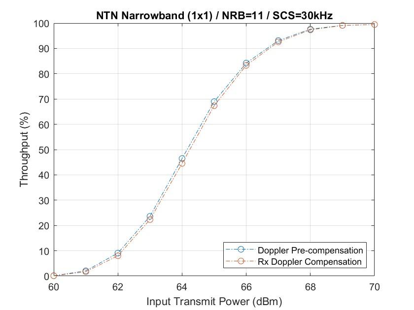
測定されたスループットを表示します。これは、データ転送に使用可能なリソースを与えられたリンクの最大可能スループットのパーセンテージです。
figure;
plot(simParameters.TxPower,simThroughput*100./maxThroughput,'o-.')
xlabel('Input Transmit Power (dBm)'); ylabel('Throughput (%)'); grid on;
title(sprintf('NTN %s (%dx%d) / NRB=%d / SCS=%dkHz', ...
    simParameters.NTNChannelType,simParameters.NumTransmitAntennas, ...
    simParameters.NumReceiveAntennas,simParameters.Carrier.NSizeGrid,...
    simParameters.Carrier.SubcarrierSpacing));

% Bundle key parameters and results into a combined structure for recording
simResults.simParameters = simParameters;
simResults.simThroughput = simThroughput;
simResults.maxThroughput = maxThroughput;
次の図は、5 MHz の伝送帯域幅を占有する 30 kHz SCS を持つキャリアの 1000 フレーム (NFrames = 1000、TxPower = 60:70) をシミュレートして得られたスループットの結果を示しています。シミュレーション設定には、 NTN狭帯域チャネルを使用したデフォルトのキャリアと PDSCH 構成が含まれます。ドップラー事前補正に対応するラインは、DopplerPreCompensator フィールドを true に、PreCompensationDopplerShift を [] に、RxDopplerCompensator フィールドを false に設定することによって実現されます。Rx ドップラー補正に対応するラインは、DopplerPreCompensator フィールドを false に、RxDopplerCompensator フィールドを true に、RxDopplerCompensationMethod フィールドを "independent time-freq" に設定することによって実現されます。
その他の調査
この例を使用して、これらのオプションをさらに詳しく調べることができます。
異なる衛星軌道の各送信電力でのスループットを解析するには、衛星の高度と衛星の速度を変更します。
ドップラー補正技術を使用せずにリンク パフォーマンスを観察するには、
DopplerPreCompensatorフィールドとRxDopplerCompensatorフィールドをfalseに設定します。ドップラー事前補償がなく、受信技術を使用してドップラーシフトを補償する場合のリンク パフォーマンスを観察するには、
DopplerPreCompensatorフィールドをfalseに設定し、RxDopplerCompensatorフィールドをtrueに設定します。受信機のドップラー補正には、「ジョイント時間周波数」または「独立時間周波数」方式のいずれかを選択します。さまざまなシナリオのスループット パフォーマンスを確認するには、キャリア番号と送信アンテナと受信アンテナの数を変更し、チャネルモデル タイプを TDL に設定します。
伝播遅延がある場合のスループット パフォーマンスを確認するには、
DelayModelを"Static"または"Time-varying"に設定します。NTNと地上ネットワークのスループット パフォーマンスを比較するには、NR PDSCH スループット (5G Toolbox) に示すように、
nrTDLChannel(5G Toolbox) およびnrCDLChannel(5G Toolbox)チャネルオブジェクトを使用します。
サポート ファイル
この例では、次のヘルパー関数を使用します。
HARQEntity— 並列HARQプロセスのセットを管理するhSkipWeakTimingOffset— 弱い相関関係を持つタイミングオフセット推定をスキップするHelperNRNTNThroughput— 例で使用されるサポート関数を定義するクラス
参考文献
[1] 3GPP TS38.211.「NR; 物理チャネルと変調。」3rd Generation Partnership Project; Technical Specification Group Radio Access Network.
[2] 3GPP TS38.212.「NR;多重化とチャネル符号化」3rd Generation Partnership Project; Technical Specification Group Radio Access Network.
[3] 3GPP TS38.213.「NR; 制御のための物理レイヤー手順」3rd Generation Partnership Project; Technical Specification Group Radio Access Network.
[4] 3GPP TS38.214.「NR; データの物理レイヤー手順」3rd Generation Partnership Project; Technical Specification Group Radio Access Network.
[5] 3GPP TR38.901.「0.5~100GHzの周波数におけるチャネルモデルの研究」3rd Generation Partnership Project; Technical Specification Group Radio Access Network.
[6] 3GPP TR38.811.「非地上ネットワークをサポートするためのnew radio(NR)に関する研究」3rd Generation Partnership Project; Technical Specification Group Radio Access Network.
[7] 3GPP TR38.821.「NR が非地上ネットワークをサポートするソリューション (NTN)」3rd Generation Partnership Project; Technical Specification Group Radio Access Network.
[8] ITU-R勧告P.681-11(2019年8月)。「陸上移動衛星業務における設計システムに必要な伝搬データ」P シリーズ;無線電波伝搬。