phased.MUSICEstimator2D
Estimate 2D direction of arrival using narrowband MUSIC algorithm
Description
The phased.MUSICEstimator2D
System object™ implements the narrowband multiple signal classification
(MUSIC) algorithm for 2-D planar or 3-D arrays such as a
uniform rectangular array (URA). MUSIC is a high-resolution direction-finding algorithm
capable of resolving closely-spaced signal sources. The algorithm is based on the
eigenspace decomposition of the sensor covariance matrix.
To estimate directions of arrival (DOA):
Create the
phased.MUSICEstimator2Dobject and set its properties.Call the object with arguments, as if it were a function.
To learn more about how System objects work, see What Are System Objects?
Creation
Description
estimator = phased.MUSICEstimator2Destimator.
estimator = phased.MUSICEstimator2D(Name,Value)estimator, with each specified property Name
set to the specified Value. You can specify additional name-value pair arguments
in any order as
(Name1,Value1,...,NameN,ValueN).
Properties
Usage
Description
Input Arguments
Output Arguments
Object Functions
To use an object function, specify the
System object as the first input argument. For
example, to release system resources of a System object named obj, use
this syntax:
release(obj)
Examples
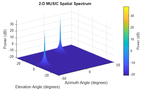
Assume that two sinusoidal waves of frequencies 450 Hz and 600 Hz strike a URA from two different directions. Signals arrive from -37° azimuth, 0° elevation and 17° azimuth, 20° elevation. Use 2-D MUSIC to estimate the directions of arrival of the two signals. The array operating frequency is 150 MHz and the signal sampling frequency is 8 kHz.
f1 = 450.0;
f2 = 600.0;
doa1 = [-37;0];
doa2 = [17;20];
fc = 150e6;
c = physconst("LightSpeed");
lam = c/fc;
fs = 8000;
Create the URA with default isotropic elements. Set the frequency response range of the elements.
array = phased.URA(Size=[11 11],ElementSpacing=[lam/2 lam/2]);
array.Element.FrequencyRange = [50.0e6 500.0e6];
Create the two signals and add random noise.
t = (0:1/fs:1).';
x1 = cos(2*pi*t*f1);
x2 = cos(2*pi*t*f2);
x = collectPlaneWave(array,[x1 x2],[doa1,doa2],fc);
noise = 0.1*(randn(size(x))+1i*randn(size(x)));
Create and execute the 2-D MUSIC estimator to find the directions of arrival.
estimator = phased.MUSICEstimator2D(SensorArray=array,...
    OperatingFrequency=fc,...
    NumSignalsSource="Property",...
    DOAOutputPort=true,NumSignals=2,...
    AzimuthScanAngles=-50:.5:50,...
    ElevationScanAngles=-30:.5:30);
[~,doas] = estimator(x + noise)
doas = 2×2

   -37    17
     0    20
The estimated DOAs exactly match the true DOAs.
Plot the 2-D spatial spectrum.
plotSpectrum(estimator);
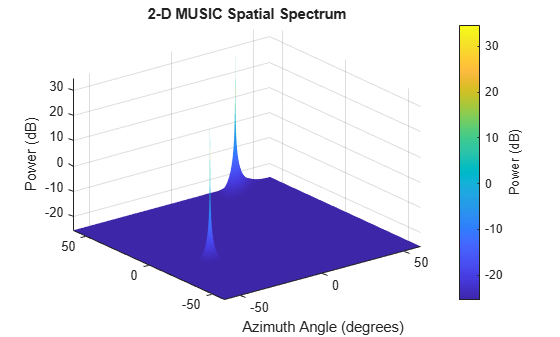
Assume that two sinusoidal waves of frequencies 1.6 kHz and 1.8 kHz strike a disk array from two different directions. The spacing between elements of the disk is 1/2 wavelength. Signals arrive from -31° azimuth, -11° elevation and 35° azimuth, 55° elevation. Use 2-D MUSIC to estimate the directions of arrival of the two signals. The array operating frequency is 300 MHz and the signal sampling frequency is 8 kHz.
f1 = 1.6e3;
f2 = 1.8e3;
doa1 = [-31;-11];
doa2 = [35;55];
fc = 300e6;
c = physconst('LightSpeed');
lam = c/fc;
fs = 8.0e3;
Create a conformal array with default isotropic elements. First, create a URA to get the element positions.
uraarray = phased.URA('Size',[21 21],'ElementSpacing',[lam/2 lam/2]);
pos = getElementPosition(uraarray);
Extract a subset of these to form an inscribed disk.
radius = 10.5*lam/2;
pos(:,sum(pos.^2) > radius^2) = [];
Then, create the conformal array using these positions.
confarray = phased.ConformalArray('ElementPosition',pos);
viewArray(confarray)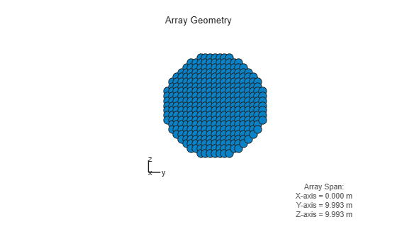
Set the frequency response range of the elements.
confarray.Element.FrequencyRange = [50.0e6 600.0e6];
Create the two signals and add random noise.
t = (0:1/fs:1.5).';
x1 = cos(2*pi*t*f1);
x2 = cos(2*pi*t*f2);
x = collectPlaneWave(confarray,[x1 x2],[doa1,doa2],fc);
noise = 0.1*(randn(size(x)) + 1i*randn(size(x)));
Create and execute the 2-D MUSIC estimator to find the directions of arrival.
estimator = phased.MUSICEstimator2D('SensorArray',confarray,...
    'OperatingFrequency',fc,...
    'NumSignalsSource','Property',...
    'DOAOutputPort',true,'NumSignals',2,...
    'AzimuthScanAngles',-60:.1:60,...
    'ElevationScanAngles',-60:.1:60);
[~,doas] = estimator(x + noise)
doas = 2×2

    35   -31
    55   -11
The estimated DOAs exactly match the true DOAs.
Plot the 2-D spatial spectrum.
plotSpectrum(estimator);
Algorithms
References
[1] Van Trees, H. L., Optimum Array Processing. New York: Wiley-Interscience, 2002.
Extended Capabilities
Version History
Introduced in R2016b