Main Content

hdlverifier.FILSimulation

FIL simulation with MATLAB

Description

The FILSimulation System object™ connects an FPGA execution to a MATLAB® testbench. It does so by applying input signals to and reading output signals from an HDL model running on an FPGA. You can use this object to model a source or sink device by configuring the object with input or output ports only.

To run a simulation consisting of a MATLAB testbench communicating with an FPGA execution:

  1. Customize the hdlverifier.FILSimulation object using FPGA-in-the-Loop Wizard.

  2. Create the object in your design and set its properties.

  3. Call the object with arguments, as if it were a function.

To learn more about how System objects work, see What Are System Objects?.

Creation

To create an hdlverifier.FILSimulation System object, use the FPGA-in-the-Loop Wizard to customize the FILSimulation System object. The output of the FILWizard is a file called toplevel_fil, where toplevel is the name of the top level HDL module. You can then create the System object by assigning it to a local variable.

filobj = toplevel_fil creates the System object customized by the FPGA-in-the-Loop Wizard. toplevel is the name of the top-level module in your HDL code.

You can create the System object and set its properties:

filobj = toplevel_fil('InputSignals', {'/top/in1','/top/in2'}, ...
                           'OutputSignals', {'/top/out1','/top/out2'}, ...
                           'OutputDataTypes', {'double','fixedpoint'}, ...
                           'OutputSigned', [true,false]);
You can also adjust writable properties after creating the System object:
filobj = toplevel_fil;
filobj.OutputDataTypes = char('fixedpoint', 'integer', 'fixedpoint');
filObj.OutputSigned = [false, true, true];

Properties

expand all

Unless otherwise indicated, properties are nontunable, which means you cannot change their values after calling the object. Objects lock when you call them, and the release function unlocks them.

If a property is tunable, you can change its value at any time.

For more information on changing property values, see System Design in MATLAB Using System Objects.

This property is read-only.

Parameters for the connection with the FPGA board, specified as a character vector or string scalar. The vector consists of three parts:

  • Connection type

  • Board IP address

  • Board MAC address (optional)

Example: char('UDP','192.168.0.2','00-0A-35-02-21-8A') specifies a UDP connection to IP address 192.168.0.2, where the board's MAC address is 00-0A-35-02-21-8A.

This property is read-only.

Design under test (DUT) top-level name, specified as a character vector or string scalar.

Example: 'inverter_top'

This property is read-only.

FPGA board name, specified as a character vector or string scalar.

Path to the FPGA programming file, specified as a character vector or string scalar.

Example: 'c:\work\filename'

This property is read-only.

Name of the FPGA chip vendor, specified as 'AMD', 'Microsemi', or 'Altera'.

Example: 'Altera'

This property is read-only.

Input widths in bits, specified as an integer or a vector of integers. When this property is an integer, all inputs have the same bit width. When this property is a vector of integers, the vector must be the same size as the number of inputs, where each value specifies a different input width.

Example: 10 – All inputs are ten bits wide.

Example: [12,6,1] – The design has three inputs: One is 12 bits wide, one is 6 bits wide, and one is 1 bit wide.

This property is read-only.

Input paths in the HDL code, specified as a character vector, cell array of character vectors, string scalar, or string array.

Example: '/top/in1'

Example: char('in1','in2')

This property is read-only.

Output widths in bits, specified as an integer or a vector of integers.

If you specify a scalar, the outputs each have the same bit width. If you specify a vector, the vector must be the same size as the number of outputs.

Example: 10 – All outputs are 10 bits wide.

Example: [12,6,1] – The design has three outputs: one is 12 bits wide, one is 6 bits wide, and one is 1 bit wide.

Output data types, specified as a character vector, cell array of character vectors, string scalar, or string array.

If you specify only one data type, all outputs have the same type. Otherwise, specify a cell array of the same size as the number of outputs.

Example: 'integer'

Example: char('integer','fixedpoint','integer')

Downsampling factor and phase of the outputs, specified as a vector of two integers. The first integer specifies the downsampling factor and is positive. The second integer specifies the phase and is either zero or positive but less than the downsampling factor.

Example: [3,1]

Output fraction lengths, specified as an integer or as a vector of integers.

If you only specify a scalar, each output has the same fraction length. Otherwise specify a vector of the same size as the number of outputs.

Example: 10 — All output fraction lengths are 10 bits.

Example: [16,8] — One output fraction length is 16 bits, and the other one has a fraction length of 8 bits.

This property is read-only.

Output port names in the HDL top-level module, specified as a character vector, cell array of character vectors, string scalar, or string array.

Example: 'out1',

Example: char('out1','out2')

Sign of the outputs, specified as false (unsigned), true (signed), or as a logical vector.

If you provide only a scalar, each output has the same sign. Otherwise, you should provide a vector of the same size as the number of outputs.

Example: true

Example: [true, true, false] — Three outputs consisting of a signed value, an unsigned value, and a signed value.

Hardware overclocking factor, specified as an integer.

Example: 3

This property is read-only.

Position of the FPGA in the JTAG scan chain, specified as a positive integer.

Example: 1

Frame size of the source, specified as an integer. This property is relevant only for HDL source blocks, that is, HDL blocks that have no inputs.

Example: 1

Usage

Description

[hdloutputs] = filobj([hdlinputs]) connects to the FPGA, writes hdlinputs to the FPGA and reads hdloutputs from the FPGA.

example

Input Arguments

expand all

Inputs to run on the FPGA, specified as an array of values. The size of the array must match the number of inputs of the module executed on the FPGA.

Example: [RealFft, ImagFft] = fft_obj(3,12); the values 3 and 12 are driven into the FPGA.

Data Types: int8 | int16 | int32 | int64 | uint8 | uint16 | uint32 | uint64 | logical | Fixed-point

Output Arguments

expand all

Outputs returned from the FPGA, specified as an array of values. The size of the array matches the number of outputs of the module executed on the FPGA.

Example: [RealFft, ImagFft] = fft_obj(real_in,imaginary_in); returns a complex number from the FPGA with two values: RealFft and ImagFft.

Data Types: int8 | int16 | int32 | int64 | uint8 | uint16 | uint32 | uint64 | logical | Fixed-point

Object Functions

To use an object function, specify the System object as the first input argument. For example, to release system resources of a System object named obj, use this syntax:

release(obj)

expand all

programFPGA Load programming file associated with FILSimulation or FILFreeRunning system object onto FPGA
stepRun System object algorithm
releaseRelease resources and allow changes to System object property values and input characteristics
resetReset internal states of System object

Examples

collapse all

This example uses a MATLAB® System object™ and an FPGA to verify a register transfer level (RTL) design of an 8-point Fast Fourier Transform (FFT) written in VHDL®. The FFT is commonly used in digital signal processing to produce the frequency distribution of a signal.

To verify this FFT, this example includes a testbench for the System object. This testbench sends a sine wave to the HDL design under test (DUT) and plots the magnitude of the FFT output.

Set Up FPGA Design Software Environment

Before using FPGA-in-the-Loop (FIL), make sure your system environment is properly configured to access your FPGA design software. You can use the hdlsetuptoolpath function to add the FPGA design software to the system path for the current MATLAB session.

Launch FIL Wizard

Launch the FIL Wizard prepopulated with the FFT example information. The DUT is an 8-point FFT module that receives real-valued input samples with a valid signal and outputs the complex FFT result along with a data valid signal.

Enter your FPGA board information in the first step, then follow each step of the wizard to generate the FPGA programming file and the FIL System object.

filWizard('filSysObjExFILWizardInfo.mat');

Instantiate the FPGA-in-the-Loop System Object

fft8_fil is a customized hdlverifier.FILSimulation System object, which represents the HDL implementation of the FFT running on the FPGA in this simulation system.

filObj = fft8_fil;

Program FPGA

Make sure the FIL Wizard has finished generating the FPGA programming file, and check that the FPGA board is powered on and connected properly. Program the FPGA with the generated programming file.

programFPGA(filObj);

Run the Simulation

The FFT input signal consists of 100 samples of a sine wave (frequency = 40 Hz, sample rate = 320 Hz, 8-bit fixed-point). The testbench can send the input signal to the FPGA as one frame, or one sample at a time. Frame-based simulation is faster and preferred when applicable. However, sample-based simulation is necessary when there is a feedback loop between the DUT input and output.

To load the test signal, enter the following at the MATLAB command prompt:

load("filSysObjExSineWave.mat","sineWave"); % 40 Hz sine wave sampled at 320 Hz

To send the entire frame to the FPGA and observe the outputs, use the System object as a function. For example:

% Frame-based simulation
[fftReal, fftImag, fftValid] = filObj(sineWave,true(100,1));

Alternatively, you can send the data to the FPGA one sample at a time.

% Sample-based simulation
for i=1:100
    [fftReal(i), fftImag(i),fftValid(i)] = filObj(sineWave(i),true);
end

Display the Simulation Result

Since the FFT algorithm has latencies, the control signal fftValid indicates that the output data is valid. To extract the valid outputs, enter these commands in the MATLAB prompt:

fftComplex = complex(fftReal, fftImag);
fftComplex = fftComplex(fftValid == true);

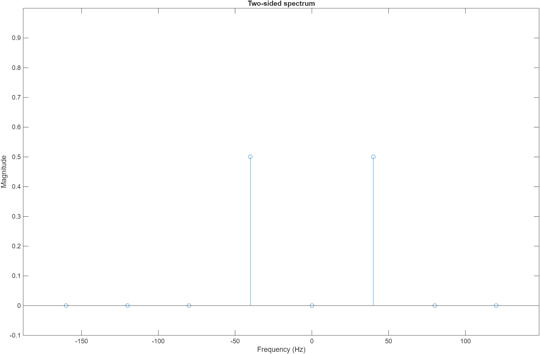
Plot the FFT magnitude on a two-sided spectrum using the first 8 samples of the FFT output. You can see the peaks at -40 Hz and 40 Hz.

N = 8; % 8-point FFT
Fs = 320; % Sample rate
stem((-N/2:N/2-1)*Fs/N, abs(fftshift(fftComplex(1:N)))/N);
xlabel('Frequency (Hz)');
ylabel('Magnitude');
title('Two-sided spectrum');
ylim([-0.1 1]);

FFT output

Release the System Object

Release the FIL System object after you finish the simulation.

release(filObj);

Version History

Introduced in R2012b