monostaticRadarSensor
Generate radar detections for tracking scenario
monostaticRadarSensor is not recommended unless you require C/C++
code generation. Use fusionRadarSensor instead. For more
information, see Version History.
Description
The monostaticRadarSensor
System object™ generates detections of targets by a monostatic surveillance scanning
radar. You can use the monostaticRadarSensor object in a scenario
containing moving and stationary platforms such as one created using trackingScenario. The monostaticRadarSensor object can
simulate real detections with added random noise and also generate false alarm
detections. In addition, you can use the detections generated by this object as input to
trackers such as trackerGNN
or trackerTOMHT.
This object enable you to configure a scanning radar. A scanning radar changes its
look angle by stepping the mechanical and electronic position of the beam in increments
of the angular span specified in the FieldOfView property. The
radar scans the total region in azimuth and elevation defined by the radar mechanical
and electronic scan limits, MechanicalScanLimits and
ElectronicScanLimits. If the scanning limits for azimuth or
elevation are set to [0 0], then no scanning is performed along that
dimension for that scan mode. If the maximum mechanical scan rate for azimuth or
elevation is set to zero, then no mechanical scanning is performed along that
dimension.
Using a single-exponential mode, the radar computes range and elevation biases caused by propagation through the troposphere. A range bias means that measured ranges are greater than the line-of-sight range to the target. Elevation bias means that the measured elevations are above their true elevations. Biases are larger when the line-of-sight path between the radar and target passes through lower altitudes because the atmosphere is thicker.
To generate radar detections:
Create the
monostaticRadarSensorobject and set its properties.Call the object with arguments, as if it were a function.
To learn more about how System objects work, see What Are System Objects?
Creation
Syntax
Description
sensor = monostaticRadarSensor(SensorIndex)SensorIndex, and default property values.
sensor = monostaticRadarSensor(SensorIndex,Name,Value)monostaticRadarSensor(1,'DetectionCoordinates','Sensor
rectangular') creates a radar detection generator that reports
detections in the sensor Cartesian coordinate system with sensor index equal
to 1.
sensor = monostaticRadarSensor(SensorIndex,'No scanning')monostaticRadarSensor that only points along the radar
antenna boresight direction. No mechanical or electronic scanning is
performed. This syntax sets the ScanMode property to
'No scanning'.
sensor = monostaticRadarSensor(SensorIndex,'Raster')monostaticRadarSensor object that mechanically scans a
raster pattern. The raster span is 90° in azimuth from –45° to +45° and in
elevation from the horizon to 10° above the horizon. See Convenience Syntaxes for
the properties set by this syntax.
sensor = monostaticRadarSensor(SensorIndex,'Rotator')monostaticRadarSensor object that mechanically scans
360° in azimuth by mechanically rotating the antenna at a constant rate.
When you set HasElevation to true,
the radar antenna mechanically points towards the center of the elevation
field of view. See Convenience Syntaxes for
the properties set by this syntax.
sensor = monostaticRadarSensor(SensorIndex,'Sector')monostaticRadarSensor
object that mechanically scans a 90° azimuth sector from –45° to +45°.
Setting HasElevation to true points
the radar antenna towards the center of the elevation field of view. You can
change the ScanMode to 'Electronic'
to electronically scan the same azimuth sector. In this case, the antenna is
not mechanically tilted in an electronic sector scan. Instead, beams are
stacked electronically to process the entire elevation spanned by the scan
limits in a single dwell. See Convenience Syntaxes for
the properties set by this syntax.
Properties
Usage
Syntax
Description
dets
= sensor(targets,interference,simTime)interference.
To enable this syntax, set the HasInterference property
to true.
Input Arguments
Output Arguments
Object Functions
To use an object function, specify the
System object as the first input argument. For
example, to release system resources of a System object named obj, use
this syntax:
release(obj)
Examples
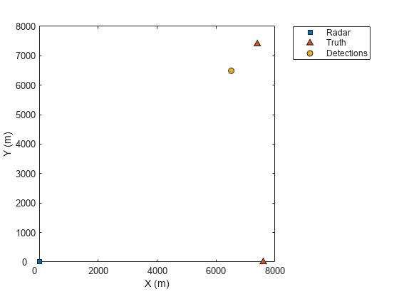
Simulate a radar scenario.
sc = trackingScenario('UpdateRate',1);Create an airport control tower with a surveillance radar located 15 meters above the ground. The radar rotates at 12.5 rpm and its field of view in azimuth is 5 degrees and its field of view in elevation is 10 degrees.
rpm = 12.5;
fov = [5;10]; % [azimuth; elevation]
scanrate = rpm*360/60;
updaterate = scanrate/fov(1) % Hz
updaterate =
15
radar = monostaticRadarSensor(1,'Rotator', ...
    'UpdateRate',updaterate, ...
    'MountingLocation',[0 0 -15], ...
    'MaxMechanicalScanRate',scanrate, ...
    'FieldOfView',fov, ...
    'AzimuthResolution',fov(1));
towermotion = kinematicTrajectory('SampleRate',1,'Position',[0 0 0],'Velocity',[0 0 0]);
tower = platform(sc,'ClassID',1,'Trajectory',towermotion);
aircraft1motion = kinematicTrajectory('SampleRate',1,'Position',[10000 0 1000],'Velocity',[-100 0 0]);
aircraft1 = platform(sc,'ClassID',2,'Trajectory',aircraft1motion);
aircraft2motion = kinematicTrajectory('SampleRate',1,'Position',[5000 5000 200],'Velocity',[100 100 0]);
aircraft2 = platform(sc,'ClassID',2,'Trajectory',aircraft2motion);
Perform 5 scans.
detBuffer = {};
scanCount = 0;
while advance(sc)
    simTime = sc.SimulationTime;
    targets = targetPoses(tower);
    [dets,numDets,config] = radar(targets,simTime);
    detBuffer = [detBuffer;dets];
    if config.IsScanDone
            scanCount = scanCount + 1;
            if scanCount == 5;
                break;
            end
    end
end
Plot detections.
tp = theaterPlot;
clrs = lines(3);
rp = platformPlotter(tp,'DisplayName','Radar','Marker','s',...
    'MarkerFaceColor',clrs(1,:));
pp = platformPlotter(tp,'DisplayName','Truth',...
    'MarkerFaceColor',clrs(2,:));
dp = detectionPlotter(tp,'DisplayName','Detections',...
    'MarkerFaceColor',clrs(3,:));
plotPlatform(rp,[0 0 0])
plotPlatform(pp,[targets(1).Position; targets(2).Position])
if ~isempty(detBuffer)
    detPos = cellfun(@(d)d.Measurement(1:3),detBuffer,...
        'UniformOutput',false);
    detPos = cell2mat(detPos')';
    plotDetection(dp,detPos)
end
More About
The sensor measures the coordinates of the target. The Measurement
and MeasurementNoise values are reported in the coordinate system
specified by the DetectionCoordinates property of the sensor.
When the DetectionCoordinates property is
'Scenario', 'Body', or 'Sensor
rectangular', the Measurement and
MeasurementNoise values are reported in rectangular coordinates.
Velocities are only reported when the range rate property,
HasRangeRate, is true.
When the DetectionCoordinates property is 'Sensor
spherical', the Measurement and
MeasurementNoise values are reported in a spherical coordinate
system derived from the sensor rectangular coordinate system. Elevation and range rate are
only reported when HasElevation and HasRangeRate
are true.
Measurements are ordered as [azimuth, elevation, range, range rate]. Reporting of
elevation and range rate depends on the corresponding HasElevation and
HasRangeRate property values. Angles are in degrees, range is in
meters, and range rate is in meters per second.
Measurement Coordinates
| DetectionCoordinates | Measurement and Measurement Noise Coordinates | |||||||||||||||
|---|---|---|---|---|---|---|---|---|---|---|---|---|---|---|---|---|
'Scenario' | Coordinate Dependence on
| |||||||||||||||
'Body' | ||||||||||||||||
'Sensor rectangular' | ||||||||||||||||
'Sensor spherical' | Coordinate Dependence on
|
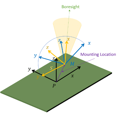
The MeasurementParameters property consists of an array of structures
that describe a sequence of coordinate transformations from a child frame to a parent frame
or the inverse transformations (see Frame Rotation). In most cases, the
longest required sequence of transformations is Sensor → Platform → Scenario.
If the detections are reported in sensor spherical coordinates and
HasINS is set to false, then the sequence
consists only of one transformation from sensor to platform. In the transformation, the
OriginPosition is same as the MountingLocation
property of the sensor. The Orientation consists of two consecutive
rotations. The first rotation, corresponding to the MountingAngles
property of the sensor, accounts for the rotation from the platform frame
(P) to the sensor mounting frame (M). The second
rotation, corresponding to the azimuth and elevation angles of the sensor, accounts for the
rotation from the sensor mounting frame (M) to the sensor scanning frame
(S). In the S frame, the x
direction is the boresight direction, and the y direction lies within the
x-y plane of the sensor mounting frame
(M).
If HasINS is true, the sequence of transformations
consists of two transformations – first form the scenario frame to the platform frame then
from platform frame to the sensor scanning frame. In the first transformation, the
Orientation is the rotation from the scenario frame to the platform
frame, and the OriginPosition is the position of the platform frame
origin relative to the scenario frame.
Trivially, if the detections are reported in platform rectangular coordinates and
HasINS is set to false, the transformation
consists only of the identity.
The fields of MeasurementParameters are shown here. Not all fields have
to be present in the structure. The set of fields and their default values can depend on the
type of sensor.
| Field | Description |
Frame | Enumerated type indicating the frame used to report
measurements. When detections are reported using a rectangular
coordinate system, |
OriginPosition | Position offset of the origin of the child frame relative to the parent frame, represented as a 3-by-1 vector. |
OriginVelocity | Velocity offset of the origin of the child frame relative to the parent frame, represented as a 3-by-1 vector. |
Orientation | 3-by-3 real-valued orthonormal frame rotation matrix. The
direction of the rotation depends on the
|
IsParentToChild | A logical scalar indicating if |
HasElevation | A logical scalar indicating if elevation is included in the
measurement. For measurements reported in a rectangular frame, and
if |
HasAzimuth | A logical scalar indicating if azimuth is included in the measurement. |
HasRange | A logical scalar indicating if range is included in the measurement. |
HasVelocity | A logical scalar indicating if the reported detections include
velocity measurements. For measurements reported in the rectangular
frame, if |
Object attributes contain additional information about a detection:
| Attribute | Description |
TargetIndex | Identifier of the platform, |
SNR | Detection signal-to-noise ratio in dB. |